Table of Contents
Advertisement
Quick Links
CAUTION: THIS UNIT IS HEAVY, PROPER EQUIPMENT AND ADEQUATE MANPOWER MUST BE USED IN MOVING THE
REMEMBER, when replacing a part on this appliance, use only spare parts that you can be assured conform to the safety and
DO NOT use reconditioned or copy parts that have not been clearly authorised by AGA.
AGA eR3
Model Nos
eR3 100-3,
eR3 100-3i,
eR3 100-4,
eR3 100-4i,
eR3 160-5,
eR3 160-5i
User Guide &
Installation Instructions
RANGE TO AVOID DAMAGE TO THE UNIT OR THE FLOOR.
performance specification that we require.
PLEASE READ THESE INSTRUCTIONS BEFORE USING THIS APPLIANCE
AND KEEP IN A SAFE PLACE FOR FUTURE REFERENCE.
For use in GB and IE
LPRT 517622
09/21 EINS 517602
Advertisement
Table of Contents

Related Manuals for AGA eR3 Series


Summary of Contents for AGA eR3 Series
- Page 1 REMEMBER, when replacing a part on this appliance, use only spare parts that you can be assured conform to the safety and performance specification that we require. DO NOT use reconditioned or copy parts that have not been clearly authorised by AGA. PLEASE READ THESE INSTRUCTIONS BEFORE USING THIS APPLIANCE AND KEEP IN A SAFE PLACE FOR FUTURE REFERENCE.
- Page 2 Useful Information It maybe useful to make a note of your AGA appliance Serial Number when it is being installed. The serial number can be found on the rear of the appliance. My AGA Details: Serial No: AGA Service No:...
-
Page 3: Table Of Contents
Conventional Fan Oven (Models 160, 160i) 2 zone induction hotplate (100/3i & 100/4i models only) AGA accessories Tall warming oven and storage area - 100 & 160 Models 10. Conventional fan oven accessories - 160 model only 11. Cleaning & Caring 12. -
Page 5: Health And Safety
WARNING : This appliance is not intended to be operated by means of an external timer not It is essential that the base or hearth on which the cooker approved by AGA or a separate remote-control and should be level and capable of supporting the total system. - Page 6 The appliance can be used by children aged from 8 years and above and persons with reduced physical, sensory or mental capabilities or lack of experience and knowledge if they have been given supervision or instruction concerning use of the appliance in a safe way and understand the hazards involved.
-
Page 7: Introduction
Your AGA is a radiant heat store cooker which combines the design values and cooking principles of the traditional AGA with the flexibility to turn each cooking area off and on as you require, thereby fitting into your lifestyle beautifully. -
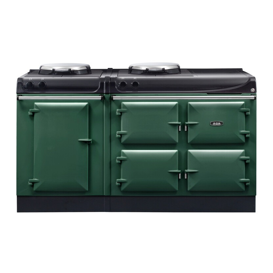
Page 8: Overview 100, 100I
Overview 100, 100i Fig. 3.1 100, 100i This model illustrate 100/4i Cooker overview Fig. 3.1 Fig. 3.2 Controls- Radiant ovens Controls- Simmering and Boiling plate (High speed) Top Oven (Roasting and Baking Oven) Simmering Oven Warming Oven Storage Oven (100/4, 100/4i only) Simmering and Boiling Plate (High speed) Top plate and resting area... -
Page 9: Overview 160, 160I
Overview 160, 160i Fig. 4.1 160, 160i This model illustrate 160i Cooker overview Fig. 4.1 Fig. 4.2 Controls- Simmering and Boiling plate (High speed) Controls- Radiant ovens Roasting and baking (Heat Store Radiant Oven) Controls- Radiant ovens Controls- Simmering and Boiling plate (High speed) Top Oven (Roasting and Baking Oven) Storage Compartment (100/4, 100/4i models only) Warming Oven... -
Page 10: Heat Storage Radiant Ovens And Main Hotplate
When switching on the AGA cooker for the first few times, there are two things you may notice, neither of which should cause concern. The AGA cooker will emit an odour for a short while, this is simply due to the protective oil we put on the hotplate and Simmering ovens burning off. - Page 11 The main Hotplate Fig. 5.1 The cast iron hotplate is operated manually and is machined flat to give the best all-over contact with the AGA saucepans, grill pan, frying pan and kettle. The boiling plate setting is the hottest with the simmering plate setting being cooler.
- Page 12 When stir-frying or cooking anything that is inclined to splash we would recommend using an AGA Splash Shield which will protect the insulated cover from splatter, making cleaning a doddle! Just wash the Splash Shield in hot soapy water or place in a dishwasher between two dinner plates.
- Page 13 Warm up times As the AGA works on the principle of storing heat, time is required to gather that heat from the electric elements to saturate the castings. We recommend to allow an hour heat...
- Page 14 The Oven Controls Fig. 5.1 To select the various oven temperature settings rotate the control knob in a clockwise direction (Fig. 5.1). Baking oven on, this setting has a modified temperature in the top left oven which is suited for baking (Fig. 5.2). Baking oven on, simmering oven on, this setting is for long, slow cooking in the bottom left hand oven (Fig.
- Page 15 As with the roasting oven setting, the specially designed AGA The beauty of the roasting oven setting is that any fat is burnt roasting tins and bakeware slide directly onto the runners,...
- Page 16 • To get the very best performance, we recommend to This element heats the air and the cast use AGA cookware with thick bases and stacking lids. iron within it to provide cooking results consistent with the traditional simmering •...
- Page 17 Cooking table - Radiant Ovens Roasting oven setting Oven temperature = HIGH Top - grilling 2nd runner - scones, small pastries, grilling 3rd runner - bread rolls , Yorkshire puddings 4th runner - roasts, poultry Oven grid shelf on base of oven - bread loaves, pies, roast vegetables Floor grid on base of oven - quiches, pies Baking oven setting Oven temperature = MODERATE...
-
Page 18: Conventional Fan Oven
Conventional Fan Oven (Models 160, 160i) Operation for Fan oven Fig. 6.1 Fan ovens circulate hot air continuously, which means faster, more even cooking. The recommended cooking temperatures for a fan oven are generally lower than those for a non-fan oven. Tall fan oven Operating the Oven Fan Oven... - Page 19 Cooking tips for your Fan Oven General oven tips The wire shelves should always be pushed firmly to the back of the oven. Baking trays with food cooking on them should be placed level with the front edge of the oven’s wire shelves. Other containers should be placed centrally.
- Page 20 Cooking Table - Fan Oven The oven will take approx 10 minutes until it has reached the selected temperature. The oven control settings and cooking times given in the table below are intended to be used as a guide only. Individual tastes may require the temperature to be altered to provide a preferred result.
- Page 21 Simmer Plate (low power) Fig. 6.9 A low power simmer plate is fitted above your conventional fan oven, it complements the high speed boiling plate on the right-hand side (Fig. 6.9). For simmer plate temperature guide, please refer to table opposite.
-
Page 22: Zone Induction Hotplate
The level of sound will vary depending on the type and style of pan used. Pan detection Timer set AGA accessories can be viewed at your local AGA specialist or online at www.agacookshop.co.uk. Residual heat Pause set... - Page 23 Residual Heat Indicator Using the Induction Hob The hob surface will get hot when in use, this is due to heat Step 1. To switch on touch the standby. being conducted from the cooking pan. The hob surface will also remain hot for a while after use. After the cooking period the hob hot indicator (Fig.
- Page 24 Pause Warming Function The warming function will keep cooked food warm for a set Step 1. To interrupt the cooking period, touch the pause. period of time. Level Temperature 40°C 104°F Melting 70°C 158°F Warming 94° C Simmer Step 1. To switch on touch the standby. Step 2.
- Page 25 Auto Cook Timer Function The Auto Cook feature allows the pan contents to be brought The timer functions do not start or stop a cooking process. up to a high temperature rapidly, before reverting back to the The hob has two individual timers: set power level.
- Page 26 1. Kitchen Timer Modify Kitchen Timer Step 1. To modify or cancel a previously set time, touch Step 1. To switch on touch the standby. the standby. Step 2. Press the “-” and “+” button together. Step 2. Press the “-” and “+” button together. Step 3.
- Page 27 2. Minute Minder Modify Minute Minder Step 1. Press the “-” and “+” button together. Step 1. To switch on touch the standby. 1 2 3 4 5 6 7 8 9 Step 2. Touch the induction on. If power level is not set Step 2.
- Page 28 3. Temporary Lock Step 1. Touch the power button. Temporary Lock, this feature will lock the controls for the duration of a cooking process to prevent accidental adjustment of the controls. Step 2. Touch the induction on. If power level is not set within 20 seconds the unit will automatically switch off.
- Page 29 Bridge Function The bridge function allows both cooking zones/elements to be switched on at the same time and controlled as one cooking zone only. This is ideal for an induction caompatible griddle or fish kettle for example. Step 1. Touch the power button. Step 2.
-
Page 30: Aga Accessories
If you have not already seen a demonstration, ask your AGA Specialist for details. A demonstration will show you how Fig. 8.2 to get the best from your new AGA and will give you hints and tips. You will also see a selection of AGA utensils and accessories being used. - Page 31 DO NOT STORE IN THE OVENS WHEN NOT IN USE. 1x Toaster (Fig. 8.6) This is for toasting bread on the boiling plate. AGA toast is renowned for its excellence, crisp on the outside and soft in the centre. Take thick slices of bread and place in the AGA...
-
Page 32: Tall Warming Oven And Storage Area - 100 & 160 Models
Tall warming oven and storage area - 100 & 160 Models Warming oven and storage area Fig. 9.1 The warming oven and storage area are supplied with two single flat cooking shelves (Fig. 9.1) which are interchangeable. ArtNo.324-0002 Oven shelf To clean the oven sides, slide out the shelves, unhook the supports from the oven sides, and lift out (Fig. -
Page 33: Conventional Fan Oven Accessories - 160 Model Only
10. Conventional fan oven accessories - 160 model only When using the tall oven, you can cook on all four shelves at Fig. 10.1 Fig. 10.2 the same time, but make sure that they are well spaced out to allow the hot air to circulate. ArtNo.324-0002 Oven shelf ArtNo.324-0010 Plate warming shelf Fig. -
Page 34: Cleaning & Caring
Induction Hob The easiest way to clean the ceramic top on plate and front plate is to mop up spills as they happen. VEA the AGA Induction hob is to mop up spills as soon as they approved AGA Enamel Cleaner can be purchased from www. -
Page 35: Maintenance
12. Maintenance • Your Aga does not need to be regularly serviced. • In the event of requiring maintenance, please call AGA Service or your authorised distributor. • Your appliance MUST only be maintained and installed by a qualified engineer, AGA engineer or an authorised distributor. -
Page 36: Installation Instructions
REMEMBER, when replacing a part on this appliance, use only spare parts that you can be assured conform to the safety and performance specification that we require. DO NOT use reconditioned or copy parts that have not been clearly authorised by AGA. PLEASE READ THESE INSTRUCTIONS BEFORE USING THIS APPLIANCE... - Page 37 14. Installation introduction Consumer protection As a responsible manufacturer, we take care to make sure that our products are designed and constructed to meet the required safety standards when properly installed and used. WARNING - ELECTRIC SHOCK HAZARD It is the customers responsibility to contact a qualified electrical installer to make sure the electrical installation is adequate and in conformance with the regulations.
-
Page 38: Product Dimensions 100, 100I
15. Product Dimensions 100, 100i Fig. 15.1 DESN 517618 NOTE: When surveying for a appliance installation the actual clearance required for the ‘body’ of the appliance should be increased overall by 10 mm beyond the figures quote above. This allows safe margin to take into account the natural dimensional variations found in major castings in particular the width across an appliance recess could be critical. -
Page 39: Product Dimensions 160, 160I
16. Product Dimensions 160, 160i Fig. 16.1 AGDN 100245 NOTE: When surveying for a appliance installation the actual clearance required for the ‘body’ of the appliance should be increased overall by 10 mm beyond the figures quote above. This allows safe margin to take into account the natural dimensional variations found in major castings in particular the width across an appliance recess could be critical. - Page 40 Side and Overhead Clearances Fig. 16.1 If you are installing the appliance in a new kitchen or have the opportunity to set the width between kitchen units, it is advisable to include an additional small gap each side of 3mm to assist with installation and prevent damage when moving the product.
- Page 41 Rear Clearances (including Combustible Rear Walls) Fig. 16.5 REAR WALL FITTING SPECIAL NOTE: Ensure that unprotected electric cabling REAR WALL FITTING or plastic services do not pass within or on the outside of the wall behind or directly above the appliance. This type of material can age prematurely when exposed to continuous higher temperature.
-
Page 42: Electrical Connection - 100, 100I
17. Electrical connection - 100, 100i WARNING: This appliance must be earthed. The method of connection to the mains electricity supply must facilitate complete electrical isolation of the appliance, This appliance is designed for the voltage stated on by a multi-pole switch, having a contact separation of at least the rating plate, which is situated behind the plinth 3 mm on all poles. -
Page 43: Electrical Connection - 160, 160I
18. Electrical connection - 160, 160i WARNING: This appliance must be earthed. The isolator should not be positioned immediately above the cooker, but must be fitted within 2 metres of the appliance. This appliance is designed for the voltage stated on the rating plate, which is situated behind the plinth The isolator maybe separate from the connection point. -
Page 44: Installation And Levelling
19. Installation and Levelling NOTE: Care must be taken not to trap mains cables (Fig. Fig. 19.1 19.1). When removing appliance from the pallet, the front stability feet can be raised with a spanner to allow appliance to be slid from transit pallet (Fig. 19.2). Slide cooker off transit pallet. - Page 45 Installation and Levelling - Fan Oven To install the conventional oven module , raise the top plate by undoing the 4 hob nuts. Fig. 19.6 Adjust the height to suit the main cooker. Lock in at the rear (Fig. 19.7). Fix with M6 bolt at front (Fig.
-
Page 46: Control Knob And Handrail Connection
20. Control knob and handrail connection Control Knob Location 100, 100i Fig. 20.1 Ensure control knobs are located onto spindles correctly, as shown in (Fig. 20.1). Control Knob Location - Conventional Oven 160, 160i HOTPLATE CONTROL KNOB HOTPLATE CONTROL KNOB (Fig. -
Page 47: Circuit Diagram 100, 100I
21. Circuit diagram 100, 100i Hotplate selector switch 2100W Hot/Simmer Spot 200W 200W Overheat stat 600W 600W Top oven Top element 300W Oven selector 600W Switch 600W Top oven bottom element 300W 600W Bottom oven element 600W 300W Connector block Fuse Transformer Push button... -
Page 48: Induction Hob
Induction Hob (100i and 160i only) Code Description Code Colour 13 A Mains Plug Blue Terminal Strip Brown Component Overheat Thermostat Black Plug And Socket Terminal Block Orange Induction Unit Violet White Yellow Green/yellow Grey... -
Page 49: Circuit Diagram Additional Fanned Oven
Circuit Diagram Additional Fanned Oven 1000W Code Description Code Colour Hotplate Selector Switch Blue Hotplate Overheat Stat Brown Hotplate Thermostat Black Hotplate Element Orange Oven Selector Switch Oven Element Violet Oven Fan White Oven Thermal Preset Yellow Green/yellow Grey... - Page 56 For further advice or information contact your local AGA Specialist. With AGA Rangemaster’s policy of continuous product improvement, the Company reserves the right to change specifications and make modifications to the appliances described and illustrated at any time. Manufactured By...
Need help?
Do you have a question about the eR3 Series and is the answer not in the manual?
Questions and answers