Table of Contents
Advertisement
Quick Links
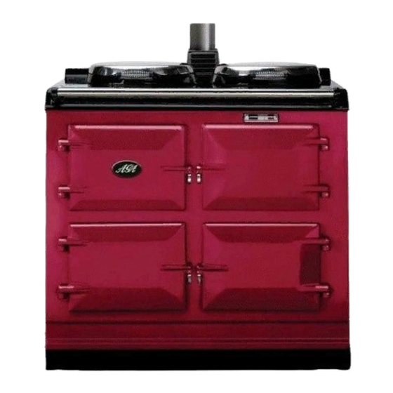
OC3 COOKER
(3-Oven Oil Fired Aga)
Installation
Instructions
REMEMBER: when replacing a part on this appliance, use only spare parts that
you can be assured conform to the safety and performance specification that we
require. Do not use reconditioned or copy parts that have not been clearly
authorised by Aga.
PLEASE READ THESE INSTRUCTIONS BEFORE INSTALLING THIS APPLIANCE
For use in GB and IE
04/08 EINS 514127
Advertisement
Table of Contents

Subscribe to Our Youtube Channel
Summary of Contents for AGA OC3
- Page 1 OC3 COOKER (3-Oven Oil Fired Aga) Installation Instructions REMEMBER: when replacing a part on this appliance, use only spare parts that you can be assured conform to the safety and performance specification that we require. Do not use reconditioned or copy parts that have not been clearly authorised by Aga.
-
Page 2: Table Of Contents
CONTENTS SECTION CONTENTS PAGE CONSUMER PROTECTION HEALTH & SAFETY SITE REQUIREMENTS TECHNICAL DATA - AGA OC3 4 -5 INTRODUCTION REGULATIONS LOCATION OIL PIPE LINE OIL STORAGE FLUE SYSTEM AIR SUPPLY ELECTRICAL SUPPLY WIRING DIAGRAM INSTALLATION SITE LOCATION REQUIREMENTS OVEN VENT & FLUE BREAK PIPE... -
Page 3: Consumer Protection
IMPORTANT NOTE: PLEASE READ THE ACCOMPANYING WARRANTY. Any alteration that it not approved by Aga could invalidate the approval of the appliance, operation of the warranty and could affect your statutory rights. -
Page 4: Technical Data - Aga Oc3
Site requirements TECHNICAL DATA - AGA OC3 FIG. 1 DESN 514131 A mm 987 967 851 679 467 1450 756 1125 64 698 889 116 41 PLEASE NOTE: SIDE CLEARANCE DIMENSION R IS ALSO REQUIRED ON THE LH SIDE FOR THE BAKING OVEN DOOR. -
Page 5: Introduction
Site requirements TECHNICAL DATA - CONTINUED Oil Inlet R1/4 (1/4” BSP Taper Ext) Smoke 0 - 1 Electrical Supply 230V ~ 50Hz 3 amp Fused Fuel - Kerosene Class C2 Flue Outlet 100 mm Unpacked Weight of Appliance - 478 Kg IN FLUE MANIFOLD 6.5 - 7.0 Firing Rate - 0.25 l/hr (COLD) -
Page 6: Oil Pipe Line
Site requirements OIL PIPE LINE OIL STORAGE SEE FIG. 2 When positioning the tank, due consideration should be given to appropriate access for fuel delivery vehicles. The oil supply connection between the storage tank and the oil pipe should be run in copper or steel pipe with a Positioning should comply with the relevant standards. -
Page 7: Flue System
Site requirements FLUE SYSTEM Chimney Terminations All chimneys should terminate above roof level, or with The flue system must be installed to the regulations in the relevant standards in force. force. Chimney Cleaning Information Ensure there are accessible airtight flue cleaning doors in Mean flue gas temperature 260ºC. -
Page 8: Air Supply
Site requirements AIR SUPPLY ELECTRICAL SUPPLY The appliance can only be installed in a room which Wiring external to the appliance must be installed in meets the ventilation regulations in force. But, in any accordance with relevant standards, wiring event the room must have a permanent vent of minimum regulations and any local regulations which apply. -
Page 9: Wiring Diagram
Site requirements WIRING DIAGRAM X1 - CONTROL BOX WIRING BASE X2 - 6 POLE CONNECTOR X3 - 6 POLE CONNECTOR (REF. ONLY) PE - PHOTOCELL OIL PUMP IGNITION TRANSFORMER VL - OIL VALVE AP - AIR PRESSURE SWITCH M - FAN MOTOR H - OIL PRE-HEATER TS - TEMPERATURE SWITCH PT - PULSE TIMER... -
Page 10: Site Location
Installation requirements SITE LOCATION 1. Check that the hearth is level, then remove the appliance from its transit wooden pallet. 2. Connect and terminate the flue system in accordance with the regulations in force. NOTE: SMOKE/SMELL EMITTED DURING INITIAL USAGE During initial usage of operation of the cooker, smoke/smell may be emitted and is normal and not a fault with the appliance, it is therefore advisable to open doors... -
Page 11: Burner Housing To Barrel
Installation requirements BURNER HOUSING TO BARREL ALIGNMENT Prior to assembly fix (4) hex head screws (M6 x 25mm long) (marked A) to the burner housing, from the rear for fixing the burner. To ensure correct fitting of burner, it is important that the 95 dia holes in the burner housing and fire barrel adaptor are in line with each other. -
Page 12: Electrical Connection
Commissioning Instructions ELECTRICAL CONNECTION SEE FIG. 7 1. Make electrical connections to terminal strip as wiring diagram. (See Fig. 7). FIG. 7 DESN 514587 OIL PUMP CONNECTION SEE FIG. 8 1. The sensing phial of the overheat stat should located on the clip provided. -
Page 13: Electrical Check
Commissioning Instructions ELECTRICAL CHECK Checks to ensure electrical safety should be carried out by a competent person. FIT PRESSURE GAUGE SEE FIG. 9 Remove the bleed screw from the manifold and fit an oil pressure gauge with R 1/8 connection to check the pump output pressure. -
Page 14: Set Combustion Air
Commissioning Instructions SET COMBUSTION AIR SEE FIG. 11 & 12 The air control of the burner is factory pre-set, however small adjustments may be necessary to suit the site conditions. Turn burner on. After 15 minutes, remove screw. Insert the sensing end of a portable indicator to check the CO (Carbon Dioxide) level. -
Page 15: Ancillary Controls Check
Commissioning Instructions ANCILLARY CONTROLS CHECK INSTRUCT THE USER In the event of flame failure the control box should cut off 1. Advise the user that, for continued efficient and safe the oil supply by closing the solenoid valve. The reset operation of the appliance, it is important that buttons will then be illuminated. - Page 16 For further advice or information contact your local Aga Specialist With Aga’s policy of continuous product improvement, the Company reserves the right to change specifications and make modifications to the appliance described and illustrated at any time Manufactured by Station Road...


Need help?
Do you have a question about the OC3 and is the answer not in the manual?
Questions and answers