AGA OC Installation Instructions Manual
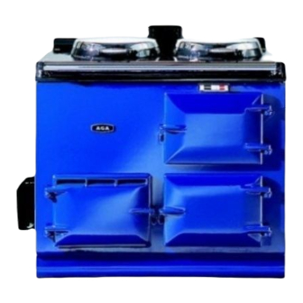
Oil fired cooker
Hide thumbs
Also See for OC:
- User instructions (9 pages) ,
- User's manual & installation instructions (32 pages)
Table of Contents
Advertisement
Quick Links
Consumer Protection Act 1987
As responsible manufacturers we take care to make sure that our
products are designed and constructed to meet the required safety
standards when properly installed and used.
IMPORTANT NOTICE: PLEASE READ THE ACCOMPANYING
WARRANTY.
Any alteration that is not approved by Aga, could invalidate the
approval of the appliance, operation of the warranty and could also
affect your statutory rights.
Control of Substances - Health and Safety
Important
This appliance may contain some of the materials that are indicated
below. It is the Users/Installers responsibility to ensure that the
necessary personal protective clothing is worn whenhandling, where
PRE-INSTALLATION ADVICE
With specific exceptions, the installing of any type of Aga
cooker is subject to the respective directions contained in
the current Building Regulations and the Building
Standards (Scotland) (Consolidation).
Practical guidance to meeting such requirements are
contained in the Approved Document J 1/4/5 - Heat
Producing Appliances in Schedule 1 of the Building
Regulations.
In addition, Planning Permission may need to be
obtained, which should be applied for separately.
THIS APPLIANCE IS A CONTROLLED SERVICE BY
DEFINITION AND REQUIRES EITHER FITMENT
UNDER THE REMIT OF BUILDING CONTROL OR
INSTALLATION BY AN OFTEC REGISTERED 105
TECHNICIAN (CLASSED AS A COMPETENT
PERSON) WHO CAN SELF CERTIFY HIS OWN
ADDITIONAL PROVISIONS
FOR AGA COOKERS
WORKS.
Such provisions for oil burning appliances are dealt with in
Section 4 of the Building Regulations where the Aga Oil
Fired Cooker, compares as follows:
Hearths
Maximum Operating Pressure 1.8 Bar
IDLING OIL
RATE - LOW FIRE
Heat Input (Btu/h)
COOKING OIL
RATE - HIGH FIRE
Heat Input (Btu/h)
Approximate Weekly
Oil Consumption
BOILER OUTPUT
AGA OIL COOKER
OC
cc per minute
3.7
7,690
cc per minute
7.0
14,550
Litres
40.0
Gallons
8.8
Installation Instructions
for Aga Oil Fired Cooker
Models OC, OCB, OE and OEB
applicable, the pertinent parts that contain any of the listed materials
that could be interpreted as being injurious to health and
safety, see below for information.
Firebricks, Fuel beds, Artificial Fuels - when handling use
disposable gloves.
Fire Cement - when handling use disposable gloves.
Glues and Sealants - exercise caution - if these are still in liquid
form use face mask and disposable gloves.
Glass Yarn, Mineral Wool, Insulation Pads, Ceramic Fibre,
Kerosene Oil - may be harmful if inhaled, may be irritating to skin,
eyes, nose and throat. When handling avoid inhaling and contact
with skin or eyes. Use disposable gloves, face-masks and eye
protection. After handling wash hands and other exposed parts.
When disposing of the product, reduce dust with water spray,
ensure that parts are securely wrapped.
1. Section 4 - Para 4.24.
A Constructional Hearth should be provided to
support the appliance
Shielding of the Appliance
2. Section 4 - Para 4.28.
The surface temperatures of the sides and back of
the appliance do not exceed 100°C and do not
therefore require shielding as described in Section 3 -
Para 3.2 (a) or (b) of the Approved Document.
Heat Exchangers – Models OCB and OEB only
This cast iron heat exchanger is 'listed' by the National
Water Council and, when correctly installed, complies
with Water Byelaws and Regulations.
The heat exchanger must be connected to a copper
double feed indirect cylinder to BS 1566 Part 1 only.
NOTE: AGA OIL FIRED COOKERS ARE DELIVERED
EX-WORKS UNASSEMBLED. ASSEMBLY IS
UNDERTAKEN ON SITE BY THE AUTHORISED AGA
DISTRIBUTOR.
Fuel
These appliances must only be used with Commercial
Kerosene current issue to BS 2869 : Class C2 suitable for
vapourising burners.
Cooker Base or Hearth
It is essential that the base or hearth on which the cooker
stands should be level, and be capable of supporting the
total weight of the respective cooker:
Models OC and OCB - 406 kg
Models OE and OEB - 584 kg
OCB
90
135
5.0
6.0
10,390
12,470
8.0
8.0
16,630
16,630
60.0
65.15
13.3
14.35
1.3 kW
2 kW
4,435 Btu
6,824 Btu
1
OE
OEB
4.4
6.0
9,145
12,470
7.0
8.0
14,550
16,630
50.9
68.4
11.2
15.05
0.9kW
3,070 Btu
04/07 EINS 510949
Advertisement
Table of Contents

Related Manuals for AGA OC


Summary of Contents for AGA OC
- Page 1 WARRANTY. Glues and Sealants - exercise caution - if these are still in liquid Any alteration that is not approved by Aga, could invalidate the form use face mask and disposable gloves. approval of the appliance, operation of the warranty and could also Glass Yarn, Mineral Wool, Insulation Pads, Ceramic Fibre, affect your statutory rights.
- Page 2 In particular, please ensure the control box mounted to byelaws of the local Water Undertaking where applicable. the side of the Aga, fire valves, isolation valves and their It should be in accordance also with any relevant line fittings are always accessible to ensure they can be...
- Page 3 The oil line from the storage tank to the appliance should cooker, by the Authorised Aga Distributor who will be fitted with a remote acting fire valve (such as a connect up to the burner.
- Page 4 24.2cm (3.7in ) for OC, OCB and OE models. Model The chimney lining should be 150mm minimum diameter OEB requires 29cm (4.5in...
- Page 5 Pipework should be insulated to help prevent heat loss Always use an Aga Transformer and possible freezing, particularly where pipes are run through roof spaces and ventilated under floor spaces. Cisterns situated in areas which may be exposed to freezing conditions should also be insulated.
- Page 6 THIS ALLOWS THE ACTUATING PLUNGER BUTTON minimum dimensions: TO EXTEND UPWARD AND GIVE HIGH FIRE OIL RATE. OIL VALVE ON L.H. SIDE USE ACTUATING LEVER WITH POWER FAILURE Model OC and OCB Model OE and OEB ONLY. Width 1303mm 1803mm 3.
- Page 7 4. Disconnect the oil flow gauge and replace oil filter and adequate servicing is carried out at regular intervals blanking plate in oil control valve. recommended by the Aga Distributor. Automatic Control The oil flow supply (heat input) is modulated by the electrical de-activation of the oil control valve top mechanism in conjunction with the control thermostat.
- Page 8 For further advice or information contact your local distributor/stockist With Aga's policy of continuous product improvement, the Company reserves the right to change specifications and make modifications to the appliances described and illustrated at any time. Manufactured By Station Road...
Need help?
Do you have a question about the OC and is the answer not in the manual?
Questions and answers