Table of Contents
Advertisement
LPRT 517622
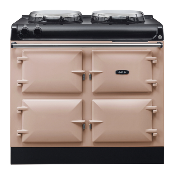
AGA eR3
Model Nos
100/3, 100/3i, 100/4, 100/4i
User Guide &
Installation Instructions
CAUTION: THIS UNIT IS HEAVY, PROPER EQUIPMENT AND ADEQUATE MANPOWER MUST BE USED IN MOVING THE
RANGE TO AVOID DAMAGE TO THE UNIT OR THE FLOOR.
REMEMBER, when replacing a part on this appliance, use only spare parts that you can be assured conform to the safety and
performance specification that we require.
DO NOT use reconditioned or copy parts that have not been clearly authorised by AGA.
PLEASE READ THESE INSTRUCTIONS BEFORE USING THIS APPLIANCE
AND KEEP IN A SAFE PLACE FOR FUTURE REFERENCE.
For use in GB and IE
04/18 EINS 517602
Advertisement
Table of Contents

Related Manuals for AGA 100/3


Summary of Contents for AGA 100/3
-
Page 1: User Guide
REMEMBER, when replacing a part on this appliance, use only spare parts that you can be assured conform to the safety and performance specification that we require. DO NOT use reconditioned or copy parts that have not been clearly authorised by AGA. PLEASE READ THESE INSTRUCTIONS BEFORE USING THIS APPLIANCE AND KEEP IN A SAFE PLACE FOR FUTURE REFERENCE. - Page 2 Useful Information It maybe useful to make a note of your AGA appliance Serial Number when it is being installed. The serial number can be found on the rear of the appliance. My AGA Details: Serial No: AGA Service No:...
-
Page 3: Table Of Contents
Health and Safety Oven shelves Shelves for warming oven and storage Introduction compartment Overview AGA accessories The Controls Accessories in your AGA eR3 Cooker hoods and oven venting Cleaning & caring The Ovens General advice Maintenance The hotplate 10. Installation instructions... -
Page 5: Health And Safety
DO NOT put oven doors or resting plates in a be operated by means of an external timer not dishwasher. approved by AGA or a separate remote-control system. The appliance can be used by children aged from 8 years and above and persons with reduced physical, sensory or mental CAUTION: The cooking process has to be supervised. - Page 6 Glass Yarn, Mineral Wool, Insulation Pads, Ceramic Fibre May be harmful if inhaled. May be irritating to skin, eyes, nose and throat. When handling avoid contact with skin or eyes. Use disposable gloves, face-masks and eye protection. After handling wash hands and other exposed parts. When disposing of the product, reduce dust with water spray, ensure that parts are securely wrapped.
-
Page 7: Introduction
Your AGA is a radiant heat stove cooker which combines the design values and cooking principles of the traditional AGA with the flexibility to turn each cooking area off and on as you require, thereby fitting into your lifestyle beautifully. -
Page 8: Overview
Simmering Plate and Boiling Plate Top Plate and Resting Area Top Oven (Roasting and Baking Oven) Simmering Oven Warming Oven Storage Compartment (100/4, 100/4i models only) Warming Plate (100/3, 100/4 models only) Induction Hotplate (100/3i, 100/4i models only). This model illustrate 100/4i... -
Page 9: The Controls
When switching on the AGA cooker for the first few times, there are two things you may notice, neither of which should cause concern. The AGA cooker will emit an odour for a short while, this is simply due to the protective oil we put on the hotplate and Simmering ovens burning off. -
Page 10: General Advice
The hotplate is set very slightly above the top plate to As the AGA works on the principle of storing heat, time is minimise scratching as the pans are pulled to one side to required to gather that heat from the electric elements to simmer. -
Page 11: Hotplate Control
When stir-frying or cooking anything that is inclined to splash we would recommend using an AGA Splash Shield which will protect the insulated cover from splatter, making cleaning a doddle! Just wash the Splash Shield in hot soapy water or place in a dishwasher between two dinner plates. -
Page 12: The Resting Plates
Replace resting plates carefully, as shown in Fig. 3.7. The ovens Fig. 3.6 Your AGA has two ovens which are pre-set at a different heat plus a warming oven, just like the traditional AGA heat storage cooker. The top oven has two temperature settings one for roasting and one for baking. -
Page 13: Roasting Oven Setting
As with the roasting oven setting, the specially designed AGA The beauty of the roasting oven setting is that any fat is burnt roasting tins and bakeware slide directly onto the runners,... -
Page 14: Simmering Oven
• To get the very best performance, we recommend to This element heats the air and the cast use AGA cookware with thick bases and stacking lids. iron within it to provide cooking results consistent with the traditional simmering •... -
Page 15: Cooking Table
Cooking table Roasting oven setting Oven temperature = HIGH Grilling Top - grilling Scones 2nd runner - scones, small pastries, grilling Pastries 3rd runner - bread rolls , Yorkshire pudding Bread 4th runner - roasts, poultry Yorkshire puddings Oven grid shelf on base of oven - bread loaves, pies, roast vegetables Roasts Floor grid on base of oven - quiches, pies Shallow frying... -
Page 16: Zone Induction Hotplate
The level of sound will vary depending on the type and style of pan used. Pan detection Timer set AGA accessories can be viewed at your local AGA specialist or online at www.agacookshop.co.uk. Residual heat Pause set... -
Page 17: Residual Heat Indicator
Residual Heat Indicator Using the Induction Hob The hob surface will get hot when in use, this is due to heat Step 1. To switch on touch the standby. being conducted from the cooking pan. The hob surface will also remain hot for a while after use. After the cooking period the hob hot indicator (Fig. -
Page 18: Pause
Pause Warming Function The warming function will keep cooked food warm for a set Step 1. To interrupt the cooking period, touch the pause. period of time. Level Temperature 40°C 104°F Melting 70°C 158°F Warming 94° C Simmer Step 1. To switch on touch the standby. Step 2. -
Page 19: Auto Cook
Auto Cook Timer Function The Auto Cook feature allows the pan contents to be brought The timer functions do not start or stop a cooking process. up to a high temperature rapidly, before reverting back to the The hob has two individual timers: set power level. -
Page 20: Kitchen Timer
1. Kitchen Timer Modify Kitchen Timer Step 1. To modify or cancel a previously set time, touch Step 1. To switch on touch the standby. the standby. Step 2. Press the “-” and “+” button together. Step 2. Press the “-” and “+” button together. Step 3. -
Page 21: Minute Minder
2. Minute Minder Modify Minute Minder Step 1. Press the “-” and “+” button together. Step 1. To switch on touch the standby. 1 2 3 4 5 6 7 8 9 Step 2. The time can now be set by using the - or +. The Step 2. -
Page 22: Temporary Lock
3. Temporary Lock Step 1. Touch the power button. Temporary Lock, this feature will lock the controls for the duration of a cooking process to prevent accidental adjustment of the controls. Step 2. Touch the induction on. If power level is not set within 20 seconds the unit will automatically switch off. -
Page 23: Bridge Function
Bridge Function The bridge function allows both cooking zones/elements to be switched on at the same time and controlled as one cooking zone only. This is ideal for an induction caompatible griddle or fish kettle for example. Step 1. Touch the power button. Step 2. -
Page 24: Oven Shelves
Oven shelves Fitting the shelves for cast iron, roasting, baking and simmering ovens Fig. 6.1 Fig. 6.2 DESN 512403 DESN 512404 Removing the shelves for cast iron, roasting, baking and simmering ovens Fig. 6.3 Fig. 6.4 DESN 512405 DESN 512406... -
Page 25: Shelves For Warming Oven And Storage Compartment
Shelves for warming oven and storage compartment Fitting and removal of shelves These shelves are designed to slide out Note: Shelf slides out to stop position. Fig. 6.5 Fig. 6.6 SHELF STOP AND ANTI TILT BRACKET STOP ON SHELF MUST PROJECT UPWARDS DESN 511867 DESN 511866... -
Page 26: Aga Accessories
If you have not already seen a demonstration, ask your AGA Specialist for details. A demonstration will show you how to get the best from your new AGA and will give you hints and tips. You will also see a selection of AGA utensils and Fig. - Page 27 DO NOT STORE IN THE OVENS WHEN NOT IN USE. 1x Toaster (Fig. 7.6) This is for toasting bread on the boiling plate. AGA toast is renowned for its excellence, crisp on the outside and soft in the centre. Take thick slices of bread and place in the AGA...
-
Page 28: Cleaning & Caring
Induction Hob The easiest way to clean the ceramic top on plate and front plate is to mop up spills as they happen. VEA the AGA Induction hob is to mop up spills as soon as they approved AGA Enamel Cleaner can be purchased from www. -
Page 29: Maintenance
Maintenance • Your AGA does not need to be regularly serviced. • In the event of requiring maintenance, please call AGA Service or your authorised distributor. • Your appliance MUST only be maintained and installed by a qualified engineer, AGA engineer or an authorised distributor. -
Page 30: Installation Instructions
REMEMBER, when replacing a part on this appliance, use only spare parts that you can be assured conform to the safety and performance specification that we require. DO NOT use reconditioned or copy parts that have not been clearly authorised by AGA. PLEASE READ THESE INSTRUCTIONS BEFORE USING THIS APPLIANCE... -
Page 31: Installation Introduction
11. Installation introduction Consumer protection As a responsible manufacturer, we take care to make sure that our products are designed and constructed to meet the required safety standards when properly installed and used. This appliance shall be installed in accordance with the regulations in force and only used in a well ventilated space. -
Page 32: Installation And Levelling
12. Installation and Levelling NOTE: Care must be taken not to trap mains cables (Fig. Fig. 12.1 12.1). When removing appliance from the pallet, the front stability feet can be raised with a spanner to allow appliance to be slid from transit pallet (Fig. 12.2). Slide cooker off transit pallet. - Page 33 Appliance can now be pushed back on its wheels into Fig. 12.3 desired position. NOTE: Care must be taken not to trap mains cable. Levelling of appliance - Use 12mm socket to adjust wheel mechanism for FINE adjustment on both sides at rear of the appliance (Fig.
-
Page 34: Product Dimensions
10 mm (3/8) beyond the figures quote above. This allows safe margin to take into account the natural dimensional variations found in major castings in particular the width across an appliance recess could be critical. Appliance weight (Excludes packaging) Model: 100/3 Weight: 300 kg... -
Page 35: 100/3I
100/3i Fig. 13.2 DESN 517619 NOTE: When surveying for a appliance installation the actual clearance required for the ‘body’ of the appliance should be increased overall by 10 mm (3/8) beyond the figures quote above. This allows safe margin to take into account the natural dimensional variations found in major castings in particular the width across an appliance recess could be critical. - Page 36 100/4 Fig. 13.3 DESN 517620 NOTE: When surveying for a appliance installation the actual clearance required for the ‘body’ of the appliance should be increased overall by 10 mm (3/8) beyond the figures quote above. This allows safe margin to take into account the natural dimensional variations found in major castings in particular the width across an appliance recess could be critical.
-
Page 37: 100/4I
100/4i Fig. 13.4 DESN 517621 NOTE: When surveying for a appliance installation the actual clearance required for the ‘body’ of the appliance should be increased overall by 10 mm (3/8) beyond the figures quote above. This allows safe margin to take into account the natural dimensional variations found in major castings in particular the width across an appliance recess could be critical. - Page 38 Side and Overhead Clearances Fig. 13.5 If you are installing the appliance in a new kitchen or have the opportunity to set the width between kitchen units, it is advisable to include an additional small gap each side of 3mm to assist with installation and prevent damage when moving the product.
- Page 39 Rear Clearances (including Combustible Rear Walls) Fig. 13.7 SPECIAL NOTE: Ensure that unprotected electric cabling REAR WALL FITTING or plastic services do not pass within or on the outside of the wall behind or directly above the appliance. This type of material can age prematurely when exposed to continuous higher temperature.
-
Page 40: Electrical Connection
14. Electrical connection WARNING: This appliance must be earthed. The method of connection to the mains electricity supply must facilitate complete electrical isolation of the appliance, This appliance is designed for the voltage stated on by a multi-pole switch, having a contact separation of at least the rating plate, which is situated behind the plinth 3 mm on all poles. -
Page 41: Control Knob And Handrail Connection
15. Control knob and handrail connection Control Knob Location Fig. 15.1 Ensure control knobs are located onto spindles correctly, as shown in (Fig. 15.1). Handrail Location HOTPLATE CONTROL KNOB Locate handrail onto spindle, lock into position with grub screws (located on the inside of the bracket) (Fig. 15.2). OVEN CONTROL KNOB DESN 517654... -
Page 42: Circuit Diagram
16. Circuit diagram Cooker eR3 Wiring Diagram: Code Description Code Description Code Colour Code Description Code Description Code Colour Upper Oven Overheat Switch Blue Hotplate Overheat Thermostat Hotplate Overheat Thermostat Lower Oven Overheat Switch Blue Brown Lower Oven Overheat Switch Hotplate Selector Switch Black Hotplate Selector Settings... - Page 43 Induction Hob Code Description Code Colour 13 A Mains Plug Blue Terminal Strip Brown Component Overheat Thermostat Black Plug And Socket Terminal Block Orange Induction Unit Violet White Yellow Green/yellow Grey...
- Page 44 Notes...
- Page 45 Notes...
- Page 46 Notes...
- Page 47 Notes...
- Page 48 For further advice or information contact your local AGA Specialist. With AGA Rangemaster’s policy of continuous product improvement, the Company reserves the right to change specifications and make modifications to the appliances described and illustrated at any time. Manufactured By...
Need help?
Do you have a question about the 100/3 and is the answer not in the manual?
Questions and answers