
Related Manuals for ClimateMaster VZ Series


Summary of Contents for ClimateMaster VZ Series
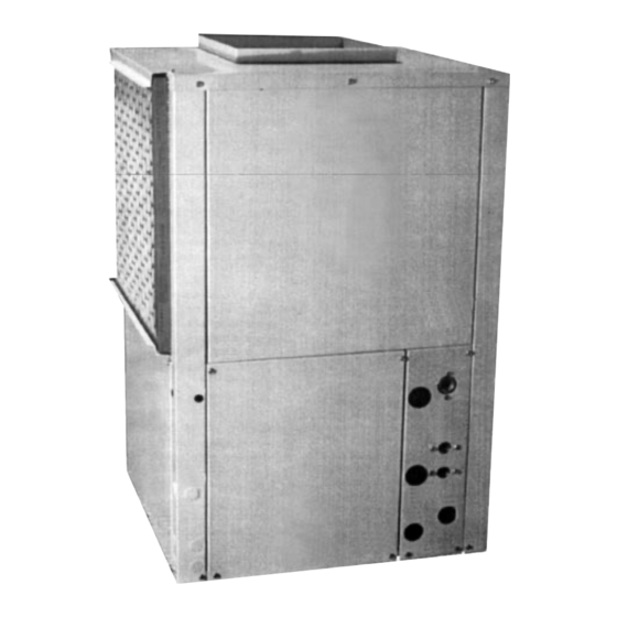
- Page 1 VZ Series Vertical Series Water Source Heat Pumps Installation, Operating & Maintenance Instructions...
-
Page 2: Table Of Contents
Maintenance ClimateMaster works continually to improve its products. As a result, the design and specifications of each product at the time for order may be changed without notice and may not be as described herein. Please contact ClimateMaster’s Customer Service Department at 1-405-745-6000 for specific information on the current design and specifications. -
Page 3: General Information
Store units in an upright position at all times. quickly becomes clogged with construction dirt and Stack VZ Series units up to a maximum of 3 units high. debris which may cause system damage. Do not remove equipment from shipping cartons until equipment is required for installation. -
Page 4: Vz Series Units Location And Access
VZ Series Units Location and Access VZ Series Units are typically installed in a floor level 2. Provide access for fan and fan motor maintenance and closet or in a small mechanical room. Refer to Figure 1 for servicing the compressor and coils without removal for an illustration of a typical installation. -
Page 5: Installation
INSTALLATION tight plus one quarter turn. Tighten steel fittings as The installation of VZ Series Water Source Heat Pump necessary. units and all associated components, parts and accesso- ries that make up the installation shall be in accordance Ensure that the trap is filled with water before operating... -
Page 6: Installing A Vz Series Unit
Installing a VZ Series Unit Return Air Louver or Grille ELECTRICAL WIRING VZ Series units are typically installed on the floor or on shelves designed to support the weight of the unit. Install the unit on a piece of rubber or neoprene for sound WARNING isolation. -
Page 7: Operating Limits
For additional wiring information pertinent to units NOTES supplied with a ClimateMaster CMC-2000 Series control 1. These are not normal or continuous operating condi- board, refer to the CMC-2000 Series Installation, Opera- tions. This assumes a winter start-up to bring the tion and Maintenance Manual (p/n 69626505) supplied building space up to occupancy temperatures. -
Page 8: Closed Loop Earth Coupled Applications
CLOSED LOOP EARTH COUPLED APPLICATIONS Introduction lines and at least 10 feet from privies and wells. Trenches may be CAUTION curved to avoid obstructions and may be turned around corners. The following instructions represent industry accepted installation practices for Closed Loop Earth Coupled When multiple pipes are laid in a trench, space pipes properly and Heat Pump Systems. -
Page 9: Building Entry
Building Entry Pier and Beam (crawl space) New and Retrofit Construction: Bury the pipe beneath the Seal and protect the entry point of the earth coupling into footing and between piers to the point that it is directly the building as shown in Figures 4-7 below. below the point of entry into the building. -
Page 10: Loop Testing
WARNING Horizontal Systems: Test individual loops as installed. Test entire system when all loops are assembled. Do not use calcium chloride in ClimateMaster units. The use of calcium chloride voids the equipment warranty. Vertical U-Bends and Pool Loop systems: Test Vertical U- bends and pond loop assemblies prior to installation with a test pressure of at least 100 psi. -
Page 11: Start-Up Preparation
System Cleaning and Flushing VZ Series units. Refill the system and bleed off all air. Cleaning and flushing the unit is the single most impor- 9. Test the system pH with litmus paper. The system tant step to ensure proper start-up and continued efficient water should be slightly alkaline ( pH 7.5 to 8.5). - Page 12 Warning 12) Replace valve plugs. To prevent equipment damage, flush/purge with the purge pump discharge hose connected to Valve D and Maintenance: When maintenance of the Heat Pump Water the return hose connected to Valve C. Any other Circuit, the Building or the in-ground piping loop is configuration may force dirt, trash, pipe trimmings or required, close valves A and B to isolate the heat pump other foreign materials into the heat pump water...
-
Page 13: System Checkout
SYSTEM CHECKOUT 12. Standby Pump: Verify that the standby pump is Voltage: Ensure that voltage is within the properly installed and in operating condition. utilization range specifications of the unit compressor and fan motor. 13. System Controls: To ensure that no catastrophic 2. -
Page 14: Unit Start-Up
UNIT START-UP e. Refer to Table 7. Check the temperature of both Use the procedure outlined below to initiate proper unit supply and discharge water. If temperature is start-up: within rage, proceed with test. If temperature is outside operating range, check cooling refrigerant WARNING pressures. -
Page 15: Maintenance
ClimateMaster replacement parts. Substitution To remove the filter from a VZ Series unit, slide the filter other components may result in an inoperative safety out of its frame located in the return air opening at the circuit and may cause a hazardous condition. - Page 16 Part #:69197321 ClimateMaster works continually to improve its products. As a result, the design and specifications of each product at the time for order may be changed without notice and may not be as described herein. Please contact ClimateMaster’s Customer Service Department at 1-405-745-6000 for specific information on the current design and specifications.
Need help?
Do you have a question about the VZ Series and is the answer not in the manual?
Questions and answers