Table of Contents
Advertisement
Quick Links
Advertisement
Table of Contents

Related Manuals for Radiant Slim RBA CS 24 E


Summary of Contents for Radiant Slim RBA CS 24 E
- Page 1 AND MAINTENANCE MANUAL FOR FLOOR STANDING TYPE GAS BOILERS WITH DOMESTIC HOT WATER STORAGE CYLINDER RBA CS 24 E - RBA CS 100 E Model TYPE C ROOM SEALED 0694 ENGLISH Technical Specification RADIANT BRUCIATORI S.p.A. Montelabbate (PU) ITALY By Technical Department...
- Page 3 INDEX INSTALLATION INSTRUCTIONS AND WARNINGS page TECHNICAL DATA page OVERALL DIMENSIONS - EXHAUST FLUE SYSTEM page GENERAL INSTALLATION REQUIREMENTS page BOILER INSTALLATION page ELECTRICAL CONNECTIONS page 9;21-22 BOILER CONTROL PANEL page STARTING UP THE BOILER FOR THE FIRST TIME page BOILER ADJUSTMENTS page MULTIGAS OPERATION...
-
Page 4: Installation Instructions - Warnings
RADIANT BRUCIATORI S.p.A. products are type tested EC. All RADIANT boilers are constructed according to UNI - CIG (EC) norms. The materials used, such as copper, brass, and stainless steel form a compact, homogeneous, highly functional unit that is easy to install and simple to operate. The wall-mounted boiler is equipped with all of the approved accessories required to make it a true, independent heating plant for home heating and for the production of hot water for domestic needs. -
Page 5: Technical Data
Installation Manual TECHNICAL DATA Type C unit Type C devices are devices in which the combustion circuit (air intake, combustion chamber, exchanger, combustion exhaust) is sealed off from the place where they are installed. CENTRAL HEATING - DOMESTIC HOT WATER sealed combustion circuit type RBA CS 24 E - electronic ignition RBA CS 100 E - electronic ignition... - Page 6 1.5 m. R RETURN ¾” G GAS ½” C HOT WATER OUTLET ½” F COLD WATER INLET ½” A HEATING FLOW ¾” NOTE: USE ORIGINAL RADIANT APPROVED FLUE KIT SYSTEMS, FLUE ACCESSORIES AND FLUE DIAPHRAGMS ONLY. APPROVED RADIANT FLUE DIAPHRAGMS AND...
- Page 7 It allows the flue exhaust and the air intake directly to an external wall. . To insert a bend, reduce total flue length by 0.8 m. NOTE: USE ORIGINAL RADIANT APPROVED FLUE KIT SYSTEMS, FLUE ACCESSORIES AND FLUE DIAPHRAGMS ONLY. APPROVED RADIANT FLUE...
- Page 8 Installation Manual GAS SAFETY It is the law that all gas appliances are installed by a CORGI registered installer (you can check this by contacting corgi on 01256.372200) in accordance with the regulations listed below. Failure to install appliances correctly could lead to prosecution. It is in your own interest and that of safety to ensure that the law is complied with.
-
Page 9: Flue Position
Installation Manual FLUE POSITION IMPORTANT: THE FLUE SYSTEM SHALL BE INSTALLED IN ACCORDANCE WITH THE RECOMMENDATIONS CONTAINED IN BS 5440:1. The boiler MUST be installed so that the terminal is exposed to the external air. It is important that the position of the terminal allows free passage of air across it at all times. If the terminal discharges into a pathway or passageway check that combustion products will not cause nuisance and that the terminal will not obstruct the passageway. -
Page 10: Water Connections
Installation Manual MINIMUM DISTANCES FOR FIXING TO WALL To allow access in the boiler for maintenance operations, the minimum distances shown below must be respected (fig. 1 and 2): WATER CONNECTIONS To facilitate installation, the boiler is equipped with a fittings kit (see fig. 3 and mod. - Page 11 • conversion to allow the boiler to run on LPG to natural gas or vice versa must be carried out by a qualified gas fitter in accordance with law no.46 of 5th March ‘90. Table n°1 ANTI-FROST SYSTEM Antifreeze Temperature Radiant boilers are equipped with an Anti- Ethylene glycol freezing point boiling point Freeze system which comes into operation (%) volume (°C)
-
Page 12: Connection Of Room Thermostat
Installation Manual ELECTRICAL CONNECTIONS Fig. 1 The boiler works with 230 V 50 Hz AC current and has maximum input of 170 W. Connection to the electrical mains must be performed with a device having an omnipolar opening of at least 3 mm. -
Page 13: Starting Up The Boiler
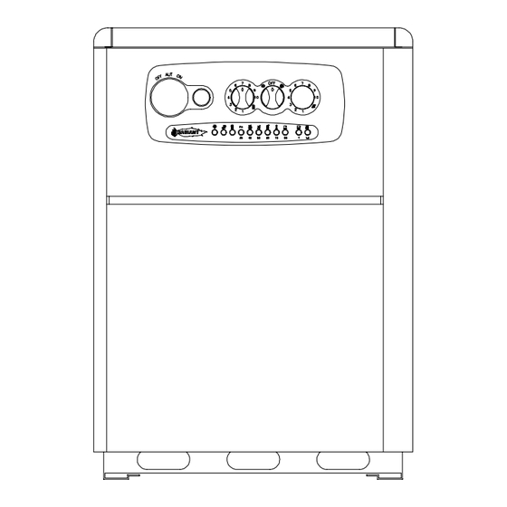
Installation Manual CONTROL PANEL LEGEND (see fig. 1) SUMMER-WINTER ON-OFF SWITCH LOCK-OUT INDICATOR HEATING TEMPERATURE ADJUSTMENT KNOB WATER TEMPERATURE ADJUSTMENT KNOB SPACE FOR ADDING AN OPTIONAL TIMER SELF- DIAGNOSTIC LEGEND (see fig. 2) OPERATING/ POWER INDICATOR DOMESTIC HOT WATER OPERATION HEATING OPERATION FLASHING LIGHT DENOTING AIR PRESSURE SWITCH Fig. -
Page 14: Emptying The Central Heating System
Installation Manual • check the pressure in the system: if this has gone down and LED 13 (see fig. 2 pag. 10) comes on restore pressure; • close the tap on the filling loop once this operation is completed; Starting up the boiler •... -
Page 15: Boiler Adjustments
Installation Manual BOILER ADJUSTMENTS SELECTOR FUSE 1 RL3-RT RL1-RP LINK PTC1 RLA - CM1 RL2-RS SELECTOR RL4-RV THE SELECTOR P1 SAN. RISC. MUST BE INSERTED INTO THE T. RIS M. RIS COMMUTATOR LINK FASX2 FASX3 SELECTOR FASX1 FASX4 NATURAL GAS COMMUTATOR L.P.G. -
Page 16: Data Table
Installation Manual CONVERSION OF GAS BURNER UNIT PRESSURE MODULATOR Link Jumper on RAMIRE GAS TYPE ciruit board Conversion of the boiler from natural gas to LPG and vice versa must be performed by qualified personnel only. Conversion is performed as LEGEND: follows: Modulating coil... -
Page 17: Regulating The Gas Pressure
Installation Manual REGULATING THE GAS PRESSURE Maximum and minimum modulation pressures. N.B. The following operations must only be carried out by authorised personnel and are necessary when the boiler is converted to run on one type of gas or another or also in cases where the maximum pressure is not the same as that shown on the plate. -
Page 18: Domestic Hot Water Production
Installation Manual TECHNICAL DATA DIFFERENTIAL AIR PRESSURE SWITCH FOR FAN CONTROL To guarantee maximum safety in flue exhaust, a differential pressure switch is installed on room-sealed boilers and on forced draught boilers. This pressure switch automatically controls perfect functioning of the fan and the passage of both external air and exhaust flue pipes. -
Page 19: Boiler Maintenance
Installation Manual BOILER MAINTENANCE (carried out by qualified heating engineers) Every 12 months, or more frequently if the quality and consumption of water demand it, check the condition of the magnesium anode and replace it if signs of wear are evident. To check the condition of the anode 3 (see fig.1), open valve 4 on the top of the boiler, undoing the red knob in a clockwise direction. - Page 20 Installation Manual LEGENDA BOTTOM BLACK BASE FLUE HOOD – ROOM SEALED COMBUSTION CHAMBER COMBUSTION CHAMBER mod. 24.000 ROOM SEALED CHAMBER COVER ROOM SEALED CHAMBER BACK HEAT EXCHANGER 66A mod. 24.000 MULTIGAS BURNER WITH 13 RAMPS mod. 24.000 IGNITION ELECTRODE FLAME IONISATION ELECTRODE HEATING SAFETY THERMOSTAT ELECTRONIC GAS VALVE VK4105 A 1001 GAS PRESSURE MODULATOR...
-
Page 21: Time Clock
Installation Manual ELECTRICAL CONNECTION FOR ROOM SEALED COMBUSTION CHAMBER ELECTRONIC IGNITION BOILER RAMIRE 3 CIRCUIT BOARD STANDARD ON ALL MODELS N.B. M1 CONNECTOR OF THE RAVI 2 CIRCUIT BOARD MUST BE CONNECTED TO THE M11 CONNECTOR OF THE RAMIRE 3 FUSE 1 CIRCUIT BOARD. - Page 22 Installation Manual WIRING DIAGRAM FOR ROOM SEALED COMBUSTION CHAMBER ELECTRONIC IGNITION BOILER – mod. RBA CS 24-100 E NET FILTER 80° 70° 60° 50° 40° 30° light-blue brown MAX. RIS TIMER RIS. RAVI2 brown SK06205 PTC2 T. RIS T. SAN light-blue black 1 bar...
-
Page 23: Maintenance
Installation Manual MAINTENANCE To keep the boiler in efficient and safe operating condition, we advise you to perform the following checks at least once a year: Check all seals on the gas side and replace gaskets to restore perfect seal as required. Check all seals on the water side and replace gaskets to restore perfect seal as required. - Page 24 Installation Manual ELECTRONIC WATER PRESSURE GAUGE SELF-DIAGNOSTIC Fig. 2 Fig. 1 MALFUNCTION POSSIBLE CAUSE SOLUTION Light 6 (fig.2) is on but nothing works. water pressure switch replace it water pressure below 0.5 bar (light 13 fig. 2 load water flashing). RAMIRE circuit board damaged replace it Light 6 (fig.2) is on, the circulation pump...
-
Page 25: Spare Parts Short List
Installation Manual SPARE PARTS SHORT LIST n° CODE DESCRIPTION RBA CS 24 E RBA CS 100 E Electronic Electronic Ignition Ignition 58007LP MAIN HEAT EXCHANGER mod. 24.000 36064LA ELECTRONIC GAS VALVE VK4105 A 1035B 76616LA ELECTRONIC IGNITION BOARD S4565 A 2019B 18003LA MODULATING COIL 97007LA... - Page 26 • Internet: http://www.radiant.it UK – Radiant Helpline – 01329.828555 All descriptions and illustrations contained in this leaflet have been carefully prepared but we reserve the right to make changes and improvements in our products whitch may affect the accurancy of the information contained in this leaflet. E + OE All rights reserved.
- Page 35 USER MANUAL RBA CS 24 E - RBA CS 100 E Models TYPE C ROOM SEALED 0694 ENGLISH Technical Specification RADIANT BRUCIATORI S.p.A. Montelabbate (PU) ITALY By Technical Department...
- Page 36 ⇒ If the boiler should freeze up, under no circumstances attempt to turn it on but call the RADIANT HELP LINE – (1329.828555) immediately.
- Page 37 Have normal maintenance performed at least once a year by one of our authorised service centres, combustion tests are necessary every two years and should again be carried out by RADIANT HELP LINE - 01329.828555. Periodically check system pressure on the pressure gauge and check that pressure is between 0.5 - 1.5 bar with the system cold.
- Page 38 • Internet: http://www.radiant.it UK – Radiant Helpline – 01329.828555 All descriptions and illustrations contained in this leaflet have been carefully prepared but we reserve the right to make changes and improvements in our products whitch may affect the accurancy of the information contained in this leaflet. E + OE All rights reserved.
Need help?
Do you have a question about the Slim RBA CS 24 E and is the answer not in the manual?
Questions and answers