Table of Contents
Advertisement
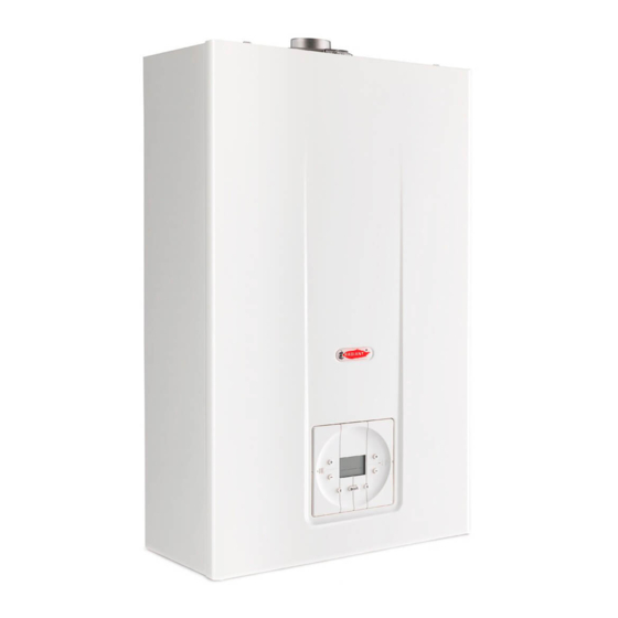
Instruction Manual
for model
RSA 24 /8
Wall mounted storage combi boiler
room sealed chamber
Installation, operating, commissioning and maintenance instructions.
CE
0694
RSA 24.8 - RAD - ING - MAN.INST - 1410.1 - DIGITECH TR - MIAH6 - E04
Technical specification RADIANT BRUCIATORI S.p.A. Montelabbate (PU) ITALY
ENGLISH
Advertisement
Table of Contents

Related Manuals for Radiant RSA 24 /8


Summary of Contents for Radiant RSA 24 /8
- Page 1 Wall mounted storage combi boiler room sealed chamber Installation, operating, commissioning and maintenance instructions. 0694 RSA 24.8 - RAD - ING - MAN.INST - 1410.1 - DIGITECH TR - MIAH6 - E04 Technical specification RADIANT BRUCIATORI S.p.A. Montelabbate (PU) ITALY ENGLISH...
-
Page 3: Table Of Contents
CONTENTS 1. General information 1.1 General warnings pag. 1.2 Product conformity pag. 2. Technical characteristics 2.1 Technical data pag. 2.2 Dimensions pag. 2.3 Internal parts of the boiler pag. 2.4 Circulation pump head/flow graph pag. 2.5 Water circuit pag. 2.6 Printed circuit board – Technical characteristics pag. - Page 4 CONTENTS 6. Maintenance (authorised personnel) 6.1 General warnings pag. 6.2 Boiler inspection pag. 6.3 Accessing the boiler pag. 6.4 Draining the central heating system pag. 6.5 Wiring diagrams pag. 6.6 Electrical connections (Option) pag. 6.7 Troubleshooting pag. 6.8 Function codes pag.
-
Page 5: General Warnings
GENERAL INFORMATION 1. GENERAL INFORMATION 1.1 General warnings Professionally qualified personnel in accordance with current laws and standards and in line with the manufacturer’s instructions must install the appliance. With ‘Professionally qualified personnel’ is intended a personnel with technical knowledge in the field of installation and maintenance of components for central heating and domestic hot water production systems for domestic and industrial use. - Page 6 GENERAL INFORMATION • As dictated by current legislation, this appliance must be installed exclusively by qualified personnel. Before starting the boiler for the first time, make sure that it is connected to a water supply and central heating system compatible with its performance characteristics. •...
-
Page 7: Product Conformity
GENERAL INFORMATION 1.2 Product conformity RADIANT BRUCIATORI S.p.A. declares that all its products are manufactured to a high specification and in compliance with the relevant standards. All RADIANT boilers are CE certified and possess technical and functional characteristics that comply with the following standards: The materials used such as copper, brass, stainless steel, etc. -
Page 8: Technical Data
INSTALLATION INSTRUCTIONS 2. TECHNICAL CHARACTERISTICS 2.1 Technical data Model RSA 24 /8 0694CO9555 CE Certification n° Appliance Type II2H3+ Appliance Category C12 - C32 - C42 - C52 - C62 - C82 25.6 Heat Input max Heat Input min (Central Heating circuit) -
Page 9: Dimensions
INSTALLATION INSTRUCTIONS 2.2 Dimensions HR HWO HEATING RETURN Ø3/4” HEATING FLOW Ø3/4” Ø3/4” COLD WATER INLET Ø1/2” HOT WATER OUTLET Ø1/2”... -
Page 10: Internal Parts Of The Boiler
INSTALLATION INSTRUCTIONS 2.3 Internal parts of the boiler LEGEND 1. FAN 2. FLUE HOOD 3. SAFETY THERMOSTAT 4. COMBUSTION CHAMBER 5. IGNITION ELECTRODE 6. BURNER 7. AIR VENT VALVE 8. PUMP 9. 3 bar PRESSURE RELIEF VALVE 10. ELECTRONIC GAS VALVE 11. -
Page 11: Circulation Pump Head/Flow Graph
INSTALLATION INSTRUCTIONS 2.4 Circulation pump head/flow graph UPS 15/50 Flow m3/h Pump head at maximum speed Pump head at second speed Pump head at minimum speed Appliance Loss... -
Page 12: Water Circuit
INSTALLATION INSTRUCTIONS 2.5 Water circuit LEGEND 1. AIR PRESSURE SWITCH 2. ROOM SEALED CHAMBER BACK 3. FAN 4. FLUE HOOD – ROOM SEALED 5. EXPANSION VESSEL 6. HEAT EXCHANGER 7. HEATING SAFETY THERMOSTAT 8. FLAME IONISATION ELECTRODE 9. IGNITION ELECTRODE 10. -
Page 13: Control Panel
INSTALLATION INSTRUCTIONS ® 2.6 DIGITECH TR Printed Circuit Board (MIAH6) Technical characteristics Adjustments possible by service personnel only Standard (30/80°C) / reduced (25-45°C) central heating temperature • Water hammer prevention function • Central Heating timer - (adjustable from 0 to 7,5 minutes) •... -
Page 14: Info Menu
INSTALLATION INSTRUCTIONS INFO Menu Press the ‘ ’ INFO Button to display the boiler data. Once pressed, the parameter number will appear on the left side of the display and the associated parameter value will appear on the centre of the display. Use ‘ ’... -
Page 15: Reference Standard
INSTALLATION INSTRUCTIONS 3. INSTALLATION 3.1 Reference standard Failure to install a gas appliance correctly and in accordance with the above norms could lead to prosecution. It is in the interest of the installer and safety that the law is complied with. The manufacturers instructions form an integral part of the installation and should be left with the appliance but do not over ride in anyway statutory obligations. -
Page 16: Unpacking
Lift the boiler by grasping the rear part and proceed with the installation. STORAGE & HANDLING Please note that prior installation the Radiant boilers should stored horizontal position with no more than three boilers to a stack; Ensure that the boilers are... -
Page 17: Installing The Boiler
INSTALLATION INSTRUCTIONS 3.4 Installing the boiler appliance must installed ■ exclusively on a flat vertical solid wall capable of supporting its weight. The boiler should be fitted within the ■ building unless otherwise protected by a suitable enclosure i.e. garage outhouse. -
Page 18: Water Connections
INSTALLATION INSTRUCTIONS 3.5 Water connections In order to safeguard the heat exchanger and circulation pump, especially in case of boiler replacement, it is recommended that the system hot-flushed remove impurities (especially oil and grease) from the pipes and radiators. Make sure that the domestic water and central heating pipes are not used to earth the electrical system. -
Page 19: D.h.w. Circulating Loop
INSTALLATION INSTRUCTIONS 3.6 D.H.W. circulating loop In order to joint the D.H.W out loop pipe, proceed as follows: a) unscrew the ½” cap A and insert a ½” nipple; b) joint the nipple to the D.H.W. circulating pipe. -
Page 20: Gas Connection
INSTALLATION INSTRUCTIONS 3.7 Gas Connection The connection to the gas supply must be carried out by professionally qualified personnel in accordance with relevant standards: When connecting the boiler to the gas supply pipe, only use appropriate washers and gas fittings. The use of hemp, Teflon tape and similar materials is not allowed. -
Page 21: Electrical Connections
The connection to the mains power supply must be carried out by professionally qualified personnel, registered in accordance with current legislation and authorised by Radiant Bruciatori s.p.a. Always check to make sure that the appliance has an efficient earth system. This requirement is only satisfied if it has been properly connected to an efficient earth system installed in accordance with the requirements of current safety standards and carried out by professionally qualified personnel. -
Page 22: Remote Control Connection
INSTALLATION INSTRUCTIONS Remote control connection Connect the power supply to the terminal board inside the control panel as follows: a. Switch off the power supply at the main switch. b. Remove the front case panel of the boiler. c. Slacken the screws and remove plate A (see fig. 1). d. -
Page 23: Flue Connections
INSTALLATION INSTRUCTIONS 3.9 Flue connections In order to ensure that the appliance functions correctly efficiently, flue connection between the boiler and the flue terminal must be made using original components specifically designed for condensing boilers. Traditional flue components cannot be used for >2% conveying exhaust fumes from condensing boilers, nor vice versa. - Page 24 The linear equivalent of additional bends is as follows: Ø 60/100 x 90° bend = 0.8 m. Ø 60/100 x 45° bend = 0.5 m. N.B. : USE ONLY RADIANT TYPE -APPROVED FLUE SYSTEMS FOR DISCHARGING EXHAUST GASES AND DRAWING COMBUSTION AIR.
- Page 25 The addition of a bend has the effect of increasing the linear equivalent length of the duct as follows: Ø80 x 90° bend = 1.5 m Ø80 x 45° bend = 1.2 m N.B. : USE ONLY RADIANT TYPE-APPROVED FLUE SYSTEMS FOR DISCHARGING EXHAUST GASES AND DRAWING COMBUSTION AIR.
- Page 26 The linear equivalent of additional bends is as follows: Ø80/ 125 x 90° = 0.8 m Ø80/125 x 45° = 0.5 m N.B. : USE ONLY RADIANT TYPE-APPROVED FLUE SYSTEMS FOR DISCHARGING EXHAUST GASES AND DRAWING COMBUSTION AIR. Ø80 Ø80 Ø125...
- Page 27 INSTALLATION INSTRUCTIONS Adjustable Flue Diaphragms Coaxial flue kit system (horizontal-coaxial or vertical-coaxial) • Adjustable flue diaphragms have to be installed on the top of boiler. Installation Instructions: (see fig. 1): Clean the inspection collar surface; − Stick the neoprene washer paying attention to centre holes of the washer with those on the inspection collar; −...
- Page 28 INSTALLATION INSTRUCTIONS Twin pipe flue kit system Adjustable flue diaphragms have to be installed on the air intake hole on the top of the boiler. Installation Instructions: (see fig. 1): Install the Ø60mm. aluminium collar onto the flue exhaust vertical connector and fit it on the top of boiler, central −...
- Page 29 INSTALLATION INSTRUCTIONS Diaphragms system setting kit A - Horizontal-Coaxial Flue Kit System with intake / • NUMBERS FOR ADJUSTMENT exhaust pipes Ø60/100 INDICATOR kit C2 - Vertical-Coaxial Flue Kit System with intake / exhaust • pipes Ø80/125 MAXIMUM FLUE LENGTH DIAPHRAGM REGULATION (linear length) from 0.5 to 1 m...
-
Page 30: General Warnings
MAINTENANCE INSTRUCTIONS 4. COMMISSIONING THE APPLIANCE 4.1 General warnings The following operations must be carried out by professionally qualified personnel, registered in accordance with current legislation. The boiler leaves the factory pre-set and tested for burning either natural Gas or LPG. Nevertheless, when starting the boiler for the first time, make sure that the information on the rating plate corresponds to the type of gas being supplied to the boiler. -
Page 31: Filling The System
MAINTENANCE INSTRUCTIONS 4.2 Filling the system Check the properties of the water supply and AIR VENT VALVE install the appropriate treatment devices if the mains water has a hardness rating more AIR VENT VALVE PLUG than 25 °f i order to prevent scaling and eventual damage D.H.W... -
Page 32: Frost Protection
MAINTENANCE INSTRUCTIONS 4.3 Frost Protection The boiler is protected from freezing by electronic board settings and special functions that provide the starting of the burner to heat all the interested parts, when their temperature drops below the minimum preset values, protecting the boiler up to an external temperature of -10°C. The device operates as follows: The heating circuit water temperature drops below 5 °C, the burner is automatically switched ON until the water •... - Page 33 MAINTENANCE INSTRUCTIONS Heating elements Kit installation and wiring Please proceed as follows: a. Switch OFF the power supply at the main switch; b. Position the 4 resistances onto the heating flow pipe, heating return pipe, cold water pipe and domestic hot water pipe (with the exception of the gas pipe) See Fig.1. c.
-
Page 34: Starting Up The Boiler
MAINTENANCE INSTRUCTIONS 4.4 Starting up the boiler Once the system has been filled, proceed as follows: • Check that the exhaust duct is free from obstructions and correctly connected to the flue exhaust system. • Remove the front panel (see 6.3 ‘Accessing the boiler’);... -
Page 35: Parameters Table
MAINTENANCE INSTRUCTIONS 5. REGULATING THE BOILER 5.1 Parameters table PARAMETER PARAMETER TYPE OF OPERATION FUNCTION N° VALUE 00 = Instantaneous boiler (w/dual circuit exchanger) 01 = Instantaneous boiler (w/secondary d.h.w plate exch.) 02 = Storage cylinder boiler Selects the type of boiler 00-05 03 = Storage cylinder boiler with Comfort function... -
Page 36: Accessing The Parameters Menu
MAINTENANCE INSTRUCTIONS 5.2 Accessing the parameters menu To modify the preset values of the parameters reported in the previous table, open the parameter settings menu as follows: 1. Place mode selection button ‘ ’ in OFF position; 2. Keep pressed ‘ ’... -
Page 37: Setting The Parameters
MAINTENANCE INSTRUCTIONS 5.3 Setting the parameters P00 – ARAMETER SELECTS THE TYPE OF BOILER To enter the parameters menu, follow the previously described procedure (see paragraph 5.2 ‘Accessing the parameters menu’ - steps 1-5). 6. Use ‘ ’ and ‘ ’... - Page 38 MAINTENANCE INSTRUCTIONS P03 - W ARAMETER ATER HAMMER PREVENTION FUNCTION Activating this function, the D.H.W contact is delayed for 2 seconds. To enter the parameters menu, follow the previously described procedure (see paragraph 5.2 ‘Accessing the parameters menu’ - steps 1-5). 6.
- Page 39 MAINTENANCE INSTRUCTIONS P05 - C ARAMETER ENTRAL HEATING PUMP OVERRUN TIMER This parameter is used to set the pump functioning time, in heating mode, after switching off the main burner for the intervention of the room thermostat. To enter the parameters menu, follow the previously described procedure (see paragraph 5.2 ‘Accessing the parameters menu’...
-
Page 40: Gas Valve Adjustment
MAINTENANCE INSTRUCTIONS Gas valve adjustment P08 - M ARAMETER AXIMUM DOMESTIC HOT WATER OUTPUT Before switching on the boiler to adjust the setting, insert a pressure gauge in the pressure take-off point B on the gas valve (fig. 1); To enter the parameters menu, follow the previously described procedure (see paragraph 5.2 ‘Accessing the parameters menu’... - Page 41 MAINTENANCE INSTRUCTIONS P07 - M ARAMETER INIMUM CENTRAL HEATING OUTPUT 12. Enter the parameters menu and select parameter P07. The pressure gauge will indicate the gas pressure. If this pressure value is different to that on the rating plate of the boiler (see paragraph 5.4 ‘Gas Data’), use ‘...
- Page 42 MAINTENANCE INSTRUCTIONS P09 – S ARAMETER ETS THE IGNITION SEQUENCE This parameter is used to set the gas pressure during the starting up of the boiler.. To enter the parameters menu, follow the previously described procedure (see paragraph 5.2 ‘Accessing the parameters menu’ - steps 1-5).
- Page 43 MAINTENANCE INSTRUCTIONS P12 – ARAMETER SETS THE CLIMATIC COMPENSATION CURVE (w/outdoor temperature sensor only installation) The installation of an outdoor temperature sensor ( see allows paragraph ‘Electrical connections’) automatically modify the flow temperature in accordance to the outdoor temperature. The factor governing the correction is the Kd thermoregulation value, indicating the flow temperature range selected (fig.
- Page 44 MAINTENANCE INSTRUCTIONS P13 – C ARAMETER ENTRAL HEATING INIMUM ET POINT This parameter is used to set the central heating minimum user set point. To enter the parameters menu, follow the previously described procedure ( see paragraph 5.2 ‘Accessing the parameters menu’ - steps 1-5).
- Page 45 MAINTENANCE INSTRUCTIONS P15 – D. ARAMETER MAXIMUM SET POINT This parameter is used to set the D.H.W maximum user set point. To enter the parameters menu, follow the previously described procedure ( see paragraph 5.2 ‘Accessing the parameters menu’ - steps 1-5). 6.
-
Page 46: Gas Data
MAINTENANCE INSTRUCTIONS 5.5 Gas Data Technical data tables Natural Gas Liquid Butane Liquid Propane Gas G30 Gas G31 Lower Wobbe index (15°C; 1013 mbar) MJ/Nm 45.67 80.58 70.69 Nominal supply pressure mbar Main burner jets: 11 x 1.30 15 x 0.78 15 x 0.78 n°... -
Page 47: Converting The Boiler To A Different Gas Type
MAINTENANCE INSTRUCTIONS 5.7 Converting the boiler to a different gas type KEY: GAS VALVE MODULATOR INLET PRESSURE POINT OUTLET PRESSURE POINT GAS PIPE BURNER MANIFOLD 15 RAMPS GAS BURNER INJECTORS IGNITION ELECTRODES FLAME IONISATION ELECTRODES MANIFOLD FIXING SCREWS Fig. 1 MODULATOR NUT The conversion of a boiler from burning natural gas to LPG, or vice versa, must be carried out exclusively by professionally qualified personnel, registered in accordance with current legislation. -
Page 48: Maintenance (Authorised Personnel)
(authorised personnel) 6.1 General Warnings All maintenance operations must be carried out by professionally qualified personnel, authorised by Radiant Bruciatori Spa. The frequency of boiler maintenance must comply with current law and, nevertheless, should be carried out once a year. -
Page 49: Accessing The Boiler
MAINTENANCE INSTRUCTIONS 6.3 Accessing the boiler All maintenance operations require one or more of the boiler casing panels to be removed. The side panels can only be removed after the front panel has been removed. Front panel: Remove the fixing screws at the lower edge of the front panel. -
Page 50: Draining The Central Heating System
MAINTENANCE INSTRUCTIONS 6.4 Draining the central heating system If the need arises to drain the system, this can be done as follows: Switch the system to “WINTER” mode and ignite the • boiler. Switch off the power supply to the boiler. •... - Page 51 MAINTENANCE INSTRUCTIONS ® 6.5 Wiring diagrams – DIGITECH TR Printed Circuit Board (MIAH6) Key: TRA: Ignition transformer ER: Ionisation electrode EA: Ignition electrode VG: Gas valve MD: Modulator Circulating pump PA: Air pressure switch TS: Safety thermostat SR: Heating sensor SS: D.H.W sensor MF: Flowswitch micro Pacq: Water pressure switch...
- Page 52 MAINTENANCE INSTRUCTIONS 6.6 Electrical connections (Option) Connect the power supply to the terminal board located onto the control panel as follows: a. switch off the power supply at the main switch; b. remove the front case panel of the boiler. (see paragraph ‘6.3 Accessing the boiler’);...
-
Page 53: Wiring Diagrams
MAINTENANCE INSTRUCTIONS Wiring diagrams: MIAH6 Storage cylinder pre-heating timer option (only if parameter P00 = 2, 3 or 4) Telephone control Remote boiler Lock-Out indicator Option Zone Valves Management PCB (if Remote control is installed) TAZ 1 ZONE 1 Room thermostat TAZ 2 ZONE 2 Room thermostat Zone valve 1... -
Page 54: Troubleshooting
MAINTENANCE INSTRUCTIONS 6.7 Troubleshooting To display the last 5 errors, keep pressed the ‘ ’ INFO button, in OFF mode position, for 5 seconds. The errors number will appear in chronological order (-1- = first fault… -5- = last fault). Use ‘ ’... -
Page 55: Function Codes
MAINTENANCE INSTRUCTIONS ERROR PROBLEM POSSIBLE CAUSE REMEDY RESET CODE MICROPROCESSOR GENERAL PCB MALFUNCTION: IT THE PCB RESETS Automatic MALFUNCTION DETECTS A WRONG AUTOMATICALLY THE ERROR. SIGNAL . PARAMETER w. LOSS OF Manual Reset PROGRAMMING MICROPROCESSOR w. REPROGRAM PARAMETERS. (Switch off the REQUEST power supply) MEMORY. -
Page 56: Parts List
MAINTENANCE INSTRUCTIONS 6.9 Parts List Main components CODE DESCRIPTION 14-PLATE D.H.W HEAT EXCHANGER 20076LA 21035LA BURNER 11 R - 1.30 NAT.GAS PUMP UPS 15-50 CIAO 24052LA 3 BAR PRESSURE RELIEF VALVE -HTG CIRC. 25-00131 WATER PRESSURE GAUGE 25-00196 30-00023 AIR PRESSURE SWITCH 2.14 – 1.96 GAS VALVE SIT 30-00035 IGNITION ELECTRODE... - Page 57 MULTIPLEX unit 64066LA 54022LA 89116NA 64126LA 43135LA 64069LA 33027LA 89122NA 43145LA 20076LA 96032LA 61004LP 83546LP 96018LA 43150LA 43150LA 64128LA 43139LA 54022LA 54022LA 64124LA 43159LA 43150LA 25-00131 43276LA 26284LA 59015LA 54032LA 64123LA 25-00196 43248LA 41016LA 64075LA 67007LA 67038LA 54023LA 64106LA 43151LA 26127LA 26133LA 26133LA...
- Page 58 RADIANT BRUCIATORI s.p.a. Via Pantanelli, 164/166 - 61025 Loc. Montelabbate (PU) Tel. +39 0721 9079.1 • fax. +39 0721 9079279 e-mail: info@radiant • Internet: http://www.radiant.it TECHNICAL DATA MEASUREMENTS PROVIDED INFORMATION PURPOSES ONLY AND ARE NOT BINDING. THE COMPANY RESERVES THE RIGHT TO APPLY VARIATIONS WITHOUT PRIOR NOTIFICATION.
Need help?
Do you have a question about the RSA 24 /8 and is the answer not in the manual?
Questions and answers