Table of Contents
Advertisement
Quick Links
Advertisement
Table of Contents

Related Manuals for Radiant RK 100


Summary of Contents for Radiant RK 100
- Page 1 Instruction Manual for model RK 100 Premix condensing system boiler Installation, operating, commissioning and maintenance instructions. 0694 RK 100 - RAD - ING - MAN.INST – 1311.1 - DIGITECH CS MIAH4 Technical Specification RADIANT BRUCIATORI S.p.A. Montelabbate (PU) ITALY ENGLISH...
-
Page 3: Table Of Contents
CONTENTS General Information 1.1 General installation information page 1.2 Product conformity Technical characteristics 2.1 Technical data 2.2 Dimensions 2.3 Internal parts of the boiler 2.4 Water circuit 2.5 System mechanical circuit 2.6 Circulation pump head graph 2.7 System accessories 2.8 Printed circuit board – Technical characteristics 2.9 Control panel 2.10 INFO Menu display Installation (authorised personnel) - Page 4 CONTENTS Regulating the appliance (authorised personnel) 5.1 Parameters table page 5.2 Accesing the parameters menu 5.3 Setting the parameters 5.4 Gas Data 5.5 Regulating the Gas Valve Offset Servicing the appliance (authorised personnel) 6.1 General warnings 6.2 Boiler inspection 6.3 Accessing the boiler 6.4 Draining the central heating system 6.5 Boiler deactivation 6.6 Maintenance operations...
-
Page 5: General Information
RK 100 - RAD - ING - MAN.INST - 1311.1 - DIGITECH CS MIAH4... - Page 6 When the appliance is no longer required for use, switch off the main power supply, to switch all electrical components off (circulating pump, burner etc.) RK 100 - RAD - ING - MAN.INST - 1311.1 - DIGITECH CS MIAH4...
-
Page 7: Product Conformity
GENERAL INFORMATION 1.2 Product conformity RADIANT BRUCIATORI S.p.A. declares that all its products are manufactured to a high specification and in compliance with the relevant standards. All RADIANT boilers are CE certified and possess technical and functional characteristics that comply with the following standards: UNI EN 297 for GAS-FIRED CENTRAL HEATING BOILERS TYPE B OF NOMINAL HEAT INPUT ≤... -
Page 8: Technical Characteristics
Fan frequency – standard value (see “3.9.3 Flue kit systems“ and “5.3 Setting the parameters“) Fan frequency - enhanced value (see “3.9.3 Flue kit systems“ and “5.3 Setting the parameters“) RK 100 - RAD - ING - MAN.INST - 1311.1 - DIGITECH CS MIAH4... - Page 9 Heat Input min CO value at Heat Input max (0% O ) Weighted CO value at Heat Input min (0% O mg/kWh NOx Emissions (UNI EN 297) Class RK 100 - RAD - ING - MAN.INST - 1311.1 - DIGITECH CS MIAH4...
-
Page 10: Dimensions
TECHNICAL CHARACTERISTICS 2.2 Dimensions 2.2.1 Single unit Fig. 1 HEATING RETURN Ø1”1/2 HEATING FLOW Ø1”1/2 Ø3/4” CONDENSATE DRAIN Ø25 SAFETY VALVE DISCHARGE Ø1/2” FLUE OUTLET Ø100 RK 100 - RAD - ING - MAN.INST - 1311.1 - DIGITECH CS MIAH4... - Page 11 HEATING FLOW Ø1”1/2 HEATING RETURN Ø1”1/2 HTG FLOW TO DHW STORAGE CYLINDER Ø1” HTG RETURN FROM DHW STORAGE CYLINDER Ø1” Ø3/4” CONDENSATE DRAIN Ø25 FLUE OUTLET Ø100 RK 100 - RAD - ING - MAN.INST - 1311.1 - DIGITECH CS MIAH4...
-
Page 12: Internal Parts Of The Boiler
ELECTRONIC GAS VALVE VENTURI HEATING SAFETY THERMOSTAT 95 °C HEATING SENSOR IONISATION ELECTRODE LEFT SIDE IGNITION ELECTRODE SYSTEM DRAIN VALVE Fig. 1 SAFETY THERMO FUSE 318 °C RK 100 - RAD - ING - MAN.INST - 1311.1 - DIGITECH CS MIAH4... -
Page 13: Water Circuit
IONISATION ELECTRODE CONDENSATE PIPE CONNECTION CONDENSATE TRAP WATER PRESSURE SWITCH SAFETY THERMO FUSE 318 °C TRASFORMER LEGEND HEATING FLOW Ø1”1/2 HEATING RETURN Ø1”1/2 Ø3/4” CONDENSATE DRAIN Ø25 RK 100 - RAD - ING - MAN.INST - 1311.1 - DIGITECH CS MIAH4... -
Page 14: System Mechanical Circuit
Fig. 2 pos. description OUTSIDE TEMPERATURE SENSOR PRINTED CIRCUIT BOARD – CONTROL PANEL REMOTO LCD OPEN THERM DHW CYLINDER SENSOR RK 100 - RAD - ING - MAN.INST - 1311.1 - DIGITECH CS MIAH4... -
Page 15: Circulation Pump Head Graph
2.6.2 Hydraulic pressure losses (Pressure loss mbar – Flow l/h) 1500 2500 3500 4500 5500 6500 litres/h individual boiler individual boiler + storage cylinder installation Fig. 2 RK 100 - RAD - ING - MAN.INST - 1311.1 - DIGITECH CS MIAH4... -
Page 16: System Accessories
Fig. 1 thermal carriers flows and the consequently boiler safeguard. Unfortunately in this case, a real separation of flows provokes a real output loss from the system. RK 100 - RAD - ING - MAN.INST - 1311.1 - DIGITECH CS MIAH4... -
Page 17: Printed Circuit Board - Technical Characteristics
‘-‘ PRESSED FOR 5 SECONDS TO ACTIVATE THE Fig. 1 DISPLAY BACKLIT MODE FOR A CONTINUOUS PERIOD OF 10 MINUTES. TERMINAL BLOCK FOR EXTERNAL WIRING. LCD DISPLAY. RK 100 - RAD - ING - MAN.INST - 1311.1 - DIGITECH CS MIAH4... -
Page 18: Info Menu Display
Solar storage cylinder temperature (high level) (only with Solar PCB connected) Solar panel sensor temperature 2 (only with Solar PCB connected) Solar storage cylinder temperature (extra) (only with Solar PCB connected) RK 100 - RAD - ING - MAN.INST - 1311.1 - DIGITECH CS MIAH4... -
Page 19: Installation (Authorised Personnel)
The manufacturers instructions form an integral part of the installation and should be left with the appliance but do not over ride in anyway statutory obligations. RK 100 - RAD - ING - MAN.INST - 1311.1 - DIGITECH CS MIAH4... -
Page 20: Boiler Room - Installation Requirements
Ensure that the boilers are stored in dry conditions and be aware that the carton is a tow-man lift; Fig. 1 RK 100 - RAD - ING - MAN.INST - 1311.1 - DIGITECH CS MIAH4... -
Page 21: Installing The Boiler
In order to allow access to the interior of the boiler for maintenance purposes, it is important that the minimum distances indicated in figure 1 are respected. RK 100 - RAD - ING - MAN.INST - 1311.1 - DIGITECH CS MIAH4... -
Page 22: Fixing The Boiler To Wall
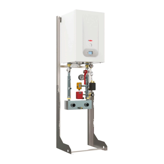
5. Once the fixing is completed check that the 4° slope (fig. 2) is respected; Fig. 1 74300LP staffa supporto caldaia 74304LP staffa distanziale Fig. 3 Fig. 2 RK 100 - RAD - ING - MAN.INST - 1311.1 - DIGITECH CS MIAH4... - Page 23 Once the assembling has been completed, place the frame by fixing it to the wall 9 and to the floor 10; Install the boiler on the frame by using the apposite hooks 11 and complete the installation with the hydraulic components mounting. Fig. 1 RK 100 - RAD - ING - MAN.INST - 1311.1 - DIGITECH CS MIAH4...
-
Page 24: Water Connections
3.6.2 Hydraulic connections LEGEND HEATING RETURN Ø1”1/2 HEATING FLOW Ø1”1/2 Ø3/4” CONDENSATE DRAIN Ø25 SAFETY VALVE DISCHARGE Ø1/2” Fig. 1 RK 100 - RAD - ING - MAN.INST - 1311.1 - DIGITECH CS MIAH4... -
Page 25: Central Heating Circuit
Neutral point is on the 6,8-7 value; in case of lower value the condensate is acid, in case of a higher value it is basic. No-trated condensate pH can be determinated by immersing the litmus paper inside the carbon site pipe. RK 100 - RAD - ING - MAN.INST - 1311.1 - DIGITECH CS MIAH4... - Page 26 (see “installation instruction”). Disposal: The reagent destination is the dump. The reagent doesn’t contain toxic substances. For the active carbons’ filter, see “six-montly maintenance”. Fig. 1 RK 100 - RAD - ING - MAN.INST - 1311.1 - DIGITECH CS MIAH4...
-
Page 27: Gas Connection
■ The gas supply pressure must be between the values reported on the rating plate (see gas type label inside the boiler). ■ Prior to installation, it is good practice to ensure that there are no machining residues on the gas supply pipe. RK 100 - RAD - ING - MAN.INST - 1311.1 - DIGITECH CS MIAH4... -
Page 28: Electrical Connections
Do not leave the appliance exposed to atmospheric elements (rain, sun, etc,) unless these conditions have been expressly provided for. Do not allow the appliance to be used by children or anyone unfamiliar with its operation; RK 100 - RAD - ING - MAN.INST - 1311.1 - DIGITECH CS MIAH4... - Page 29 When the wires have been connected, place plate “A" back to position. blue yellow/green brown wiring by the installer Fig. 1 BIPOLAR SWITCH BREAKER GENERAL 2x16A power supply 230V 50Hz RK 100 - RAD - ING - MAN.INST - 1311.1 - DIGITECH CS MIAH4...
- Page 30 The communication between the electronic board and the remote control takes place regardless of the mode of operation selection made in the boiler, and once the connection is established, the onboard user interface is disabled and the display will show the symbol RK 100 - RAD - ING - MAN.INST - 1311.1 - DIGITECH CS MIAH4...
- Page 31 ZONE 2 Room thermostat Zone valve 1 Zone valve 2 Zone valve Remote control Zone valve limit switch Bus adjustment input 0-10V BUS+ 0-10V 0-10V Fig. 1 RK 100 - RAD - ING - MAN.INST - 1311.1 - DIGITECH CS MIAH4...
- Page 32 M4 terminal block respecting the following coupling: light-blue – terminal no.9; brown – terminal no.8; black – terminal no.10 Fig. 1 RK 100 - RAD - ING - MAN.INST - 1311.1 - DIGITECH CS MIAH4...
-
Page 33: Flue Connections
Particularly, joints must be condensate tight. To avoid that the condensate produced inside the flue hood flows into the boiler, proper drain points connected to a condensate trap must be previewed. RK 100 - RAD - ING - MAN.INST - 1311.1 - DIGITECH CS MIAH4... - Page 34 Extension Ø100 L = 1000 mm MF polypropylene Vertical connector Ø100 w/test point MF polypropylene 90° Flue bend Ø100 MF polypropylene 17.5 45° Flue bend Ø100 MF polypropylene RK 100 - RAD - ING - MAN.INST - 1311.1 - DIGITECH CS MIAH4...
- Page 35 Extension Ø100 L = 1000 mm MF polypropylene Vertical connector Ø100 w/test point MF polypropylene 90° Flue bend Ø100 MF polypropylene 17.5 45° Flue bend Ø100 MF polypropylene RK 100 - RAD - ING - MAN.INST - 1311.1 - DIGITECH CS MIAH4...
-
Page 36: Commissioning The Appliance (Authorised Personnel)
Check that circulating pumps freely rotate. Unscrew the inspection screw and verify with a flat screwdriver that the impeller works without obstructions. Prior to loosen or remove the circulating pump cap, protect the electrical devices below from possible leaks of water. RK 100 - RAD - ING - MAN.INST - 1311.1 - DIGITECH CS MIAH4... -
Page 37: Filling The System
If, after the above operations, there is a pressure reduction, re-open the external filling loop valve until the pressure gauge reaches 1.2 ÷ 1.5 bar. On completion, make sure that the filling loop is turned off; RK 100 - RAD - ING - MAN.INST - 1311.1 - DIGITECH CS MIAH4... - Page 38 A chemical treatment is necessary if the limit of values above is exceeded. The choice of the water treatment type must be made according to the water features, the system type and the pureness limit requested. RK 100 - RAD - ING - MAN.INST - 1311.1 - DIGITECH CS MIAH4...
-
Page 39: Filling The Condensate Trap
Such deposits may cause the malfunction of the siphon. Fig. 1 RK 100 - RAD - ING - MAN.INST - 1311.1 - DIGITECH CS MIAH4... -
Page 40: Frost Protection
Connect the power supply cables to the terminal board located onto the control panel and following the wiring instruction; Secure the cables between them using the supplied clamps. RK 100 - RAD - ING - MAN.INST - 1311.1 - DIGITECH CS MIAH4... -
Page 41: Starting Up The Boiler
If the CO2 value does not correspond to the specified value, carry out adjustment as provided in paragraph “5.5.1 – Max. power supply regulation - CO value” ; RK 100 - RAD - ING - MAN.INST - 1311.1 - DIGITECH CS MIAH4... -
Page 42: Regulating The Appliance (Authorised Personnel)
Sets the minimum fan speed 33 - P11 (1Hz = 30 rpm) Displayed in hertz Sets the maximum fan speed P10 - 203 (1Hz = 30 rpm) RK 100 - RAD - ING - MAN.INST - 1311.1 - DIGITECH CS MIAH4... - Page 43 Heating Power (kW) – Fan frequency (Hz) diagram “ P06, P09, P15, P21 Only for RS version with connection to a remote storage cylinder. The boiler is NOT approved for LPG (G30 – G31); RK 100 - RAD - ING - MAN.INST - 1311.1 - DIGITECH CS MIAH4...
-
Page 44: Accesing The Parameters Menu
’ buttons of heating temperature setting to select the parameter to modify; Adjust the value of the parameter using the procedure described in the following pages. RK 100 - RAD - ING - MAN.INST - 1311.1 - DIGITECH CS MIAH4... -
Page 45: Setting The Parameters
6. Press mode selection button ‘ ’ to confirm and to render the new parameter operative. 7. To exit from the parameters menu, press simultaneously ‘ ’ and ‘ ’ buttons. RK 100 - RAD - ING - MAN.INST - 1311.1 - DIGITECH CS MIAH4... - Page 46 Press mode selection button ‘ ’ to confirm and to render the new parameter operative To exit from the parameters menu, press simultaneously ‘ ’ and ‘ ’ buttons RK 100 - RAD - ING - MAN.INST - 1311.1 - DIGITECH CS MIAH4...
- Page 47 6. Press mode selection button ‘ ’ to confirm and to render the new parameter operative. 7. To exit from the parameters menu, press simultaneously ‘ ’ and ‘ ’ buttons. RK 100 - RAD - ING - MAN.INST - 1311.1 - DIGITECH CS MIAH4...
- Page 48 6. Press mode selection button ‘ ’ to confirm and to render the new parameter operative. 7. To exit from the parameters menu, press simultaneously ‘ ’ and ‘ ’ buttons. RK 100 - RAD - ING - MAN.INST - 1311.1 - DIGITECH CS MIAH4...
- Page 49 6. Press mode selection button ‘ ’ to confirm and to render the new parameter operative. 7. To exit from the parameters menu, press simultaneously ‘ ’ and ‘ ’ buttons. RK 100 - RAD - ING - MAN.INST - 1311.1 - DIGITECH CS MIAH4...
- Page 50 The communication between the electronic board and the remote control takes place regardless of the mode of operation selection made in the boiler, and once the connection is established, the onboard user interface is disabled and the display will show the symbol RK 100 - RAD - ING - MAN.INST - 1311.1 - DIGITECH CS MIAH4...
- Page 51 6. Press mode selection button ‘ ’ to confirm and to render the new parameter operative. 7. To exit from the parameters menu, press simultaneously ‘ ’ and ‘ ’ buttons. RK 100 - RAD - ING - MAN.INST - 1311.1 - DIGITECH CS MIAH4...
- Page 52 6. Press mode selection button ‘ ’ to confirm and to render the new parameter operative. 7. To exit from the parameters menu, press simultaneously ‘ ’ and ‘ ’ buttons. RK 100 - RAD - ING - MAN.INST - 1311.1 - DIGITECH CS MIAH4...
- Page 53 6. Press mode selection button ‘ ’ to confirm and to render the new parameter operative. 7. To exit from the parameters menu, press simultaneously ‘ ’ and ‘ ’ buttons. RK 100 - RAD - ING - MAN.INST - 1311.1 - DIGITECH CS MIAH4...
-
Page 54: Gas Data
Lower Wobbe index (15°C; 1013 mbar) MJ/Nm 45.67 Nominal Supply pressure mbar Consumption (15°C; 1013 mbar) 10.42 5.4.2 Heating Power (kW) - Fan frequency (Hz) diagram RK 100 - RAD - ING - MAN.INST - 1311.1 - DIGITECH CS MIAH4... -
Page 55: Regulating The Gas Valve Offset
Once the regulation is completed, screw the cap screw (3) (fig. 2), remove the manometer and screw the pressure point screw (1) (fig. 2); RK 100 - RAD - ING - MAN.INST - 1311.1 - DIGITECH CS MIAH4... -
Page 56: Servicing The Appliance (Authorised Personnel)
If the condensate is discharged to the domestic drainage system, install an inspection trap in the condensate system prior to it entering the drainage system to interrupt the continuity between the two systems; RK 100 - RAD - ING - MAN.INST - 1311.1 - DIGITECH CS MIAH4... -
Page 57: Accessing The Boiler
Unscrew the four fixing screws and remove the cover. RK 100 - RAD - ING - MAN.INST - 1311.1 - DIGITECH CS MIAH4... -
Page 58: Draining The Central Heating System
When the applicance is no longer required for use, the necessary operation (disconnect the applicance from the main electricity / gas / water supply) must be made by qualified personnel. Fig. 1 RK 100 - RAD - ING - MAN.INST - 1311.1 - DIGITECH CS MIAH4... -
Page 59: Maintenance Operations
With the cleaning completed, re-assemble the components following the above procedure in reverse order; Finally, check the boiler to make sure that all gas and exhaust joints are tight. RK 100 - RAD - ING - MAN.INST - 1311.1 - DIGITECH CS MIAH4... - Page 60 11±1mm between ignition electrode burner, 12±1mm between detection electrode and burner, to avoid a boiler malfunction. transformer IGNITION / FLAME DETECTOR ELECTRODE POSITION RK 100 - RAD - ING - MAN.INST - 1311.1 - DIGITECH CS MIAH4...
- Page 61 CO levels (see “5.5.1 Max power supply regulation- CO value”) burner premix burner unit electric fan Fig. 2 RK 100 - RAD - ING - MAN.INST - 1311.1 - DIGITECH CS MIAH4...
- Page 62 Fig. 2 Proceed with the Off-set regulation (see “5.5 Regulating the Gas Valve Offset ”) Jets RK 100 - RAD - ING - MAN.INST - 1311.1 - DIGITECH CS MIAH4...
- Page 63 Check for any leaks from the joints and bleed off any air from the circuit. Restart the boiler, making sure that there are no gas leaks; RK 100 - RAD - ING - MAN.INST - 1311.1 - DIGITECH CS MIAH4...
- Page 64 When replacing the modulation circuit board, Fig. 1 it’s necessary to set parameter according to the boiler model (see 5.3” Setting the parameters’). modulation circuit board Fig. 2 RK 100 - RAD - ING - MAN.INST - 1311.1 - DIGITECH CS MIAH4...
-
Page 65: Wiring Diagrams
TRA: Ignition transformer Open Therm Remote control ar: Orange Thermo fuse (102 °C) Room thermostat Yellow Safety thermostat TFS: Safety thermo fuse 318°C White gr: Grey RK 100 - RAD - ING - MAN.INST - 1311.1 - DIGITECH CS MIAH4... - Page 66 TRA: Ignition transformer Outdoor temperature sensor Yellow Thermo fuse (102 °C) Open Therm Remote control White Safety thermostat Room thermostat Grey TFS: Safety thermo fuse 318°C RK 100 - RAD - ING - MAN.INST - 1311.1 - DIGITECH CS MIAH4...
-
Page 67: Troubleshooting
REPLACE PART. Automatic OR OUT OF CALIBRATION CHECK THE POWER HEATING (RESISTANCE VALUE 10 SUPPLY SENSOR kOhms AT 25 °C). CONNECTION. q. SENSOR CABLE DISCONNECTED OR WET. RK 100 - RAD - ING - MAN.INST - 1311.1 - DIGITECH CS MIAH4... - Page 68 Automatic SUPPLY OUT OF THE SUPPLY NETWORK OPERATION RANGE (THE ERROR DISAPPEARS ELECTRIC POWER AUTOMATICALLY SUPPLY WHEN THE POWER SUPPLY IS BACK WITHIN THE REQUIRED RANGE) RK 100 - RAD - ING - MAN.INST - 1311.1 - DIGITECH CS MIAH4...
-
Page 69: Diagnostics
In case of an open contact of the water pressure switch, this function can be enabled during the normal boiler operation. Once the contact is closed a purging cycle of 2 minutes is performed. RK 100 - RAD - ING - MAN.INST - 1311.1 - DIGITECH CS MIAH4... -
Page 70: Parts List
THERMO FUSE 102°C RED ISOTHERM. 86006LA SAFETY THERMOSTAT 95C° 88023LA TRANSFORMER AC1 230V AC 60 HZ 96005LA 3 BAR RELIEF VALVE ½” 96012LA AUTOMATIC AIR VENT VALVE 3/8” RK 100 - RAD - ING - MAN.INST - 1311.1 - DIGITECH CS MIAH4... - Page 71 MAINTENANCE INSTRUCTIONS RK 100 - RAD - ING - MAN.INST - 1311.1 - DIGITECH CS MIAH4...
- Page 72 Via Pantanelli, 164/166 - 61025 Montelabbate (PU) Tel. +39 0721 9079.1 • fax. +39 0721 9079279 e-mail: info@radiant • Internet: http://www.radiant.it THE TECHNICAL DATA AND MEASUREMENTS ARE PROVIDED FOR INFORMATION PURPOSES ONLY AND ARE NOT BINDING. THE COMPANY RESERVES THE RIGHT TO APPLY VARIATIONS WITHOUT PRIOR NOTIFICATION.
Need help?
Do you have a question about the RK 100 and is the answer not in the manual?
Questions and answers