Allen-Bradley D Series Manuals
Manuals and User Guides for Allen-Bradley D Series. We have 7 Allen-Bradley D Series manuals available for free PDF download: Service Manual, Troubleshooting Manual, User Manual, Installation Instructions Manual
Allen-Bradley D Series Service Manual (148 pages)
Brand: Allen-Bradley
|
Category: DC Drives
|
Size: 5 MB
Table of Contents
Advertisement
Allen-Bradley D Series Troubleshooting Manual (148 pages)
Brand: Allen-Bradley
|
Category: DC Drives
|
Size: 5 MB
Table of Contents

Allen-Bradley D Series User Manual (72 pages)
Remote I/O Adapter Module
Brand: Allen-Bradley
|
Category: I/O Systems
|
Size: 0 MB
Table of Contents
Advertisement
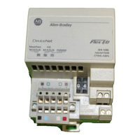
Allen-Bradley D Series Installation Instructions Manual (20 pages)
FLEX I/O ControlNet Adapter Modules
Brand: Allen-Bradley
|
Category: Adapter
|
Size: 0 MB
Table of Contents

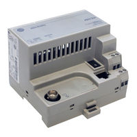
Allen-Bradley D Series Installation Instructions Manual (20 pages)
Scanner Module
Brand: Allen-Bradley
|
Category: Control Unit
|
Size: 0 MB
Table of Contents

Allen-Bradley D Series Installation Instructions Manual (12 pages)
Universal Disconnect Switch 600A
Brand: Allen-Bradley
|
Category: Switch
|
Size: 2 MB
Table of Contents
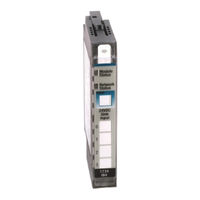
Allen-Bradley D Series Installation Instructions Manual (16 pages)
POINT I/O Input Modules
Brand: Allen-Bradley
|
Category: I/O Systems
|
Size: 1 MB