Table of Contents
Advertisement
Quick Links
5113869/01
INSTALLER GUIDE
Model 746
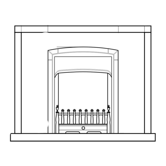
INSET LIVE FUEL EFFECT GAS FIRE
Fitted with
Blenheim Slimline,
Camden,
Coast
or
Sonnet
fascia
(GC No. 32-032-57)
THIS APPLIANCE IS FOR USE WITH NATURAL GAS (G20).
WHEN CONVERTED USING CONVERSION KIT NO. 0595221 THIS
APPLIANCE IS FOR USE WITH PROPANE GAS (G31).
THIS APPLIANCE IS SUITABLE ONLY FOR INSTALLATION IN THE UNITED
KINGDOM (GB) AND THE REPUBLIC OF IRELAND (IE).
We trust that this guide gives sufficient detail to enable this appliance to be installed and
maintained satisfactorily. However, if further information is required, our
Baxi Fires Division Technical Helpline will be pleased to help.
Telephone 08706 061 065 (National call rates apply in the United Kingdom)
In the Republic of Ireland telephone 0044 8706 061 065
owner
INSTALLER: Please leave this guide with the
© Baxi Heating U.K. Ltd.
Advertisement
Table of Contents

Subscribe to Our Youtube Channel
Related Manuals for Baxi 746


Summary of Contents for Baxi 746
- Page 1 We trust that this guide gives sufficient detail to enable this appliance to be installed and maintained satisfactorily. However, if further information is required, our Baxi Fires Division Technical Helpline will be pleased to help. Telephone 08706 061 065 (National call rates apply in the United Kingdom)
- Page 2 BS EN ISO 9001 quality system accepted by the British Standards Institute. The Highest Standards Baxi Fires Division is a member of the Society of British Gas Industries which works to ensure high standards of safety, quality and performance. Careful Installation Baxi Fires Division is a CORGI registered company.
-
Page 3: Table Of Contents
INSTALLER GUIDE CONTENTS Section Heading Page 1. SAFETY 2. APPLIANCE DATA 3. GENERAL INSTALLATION REQUIREMENTS 4. PACK CONTENTS 5. FIREPLACE CHECK 6. IGNITION CHECK 7. GAS SUPPLY CONNECTION 8. PREPARING APPLIANCE FOR INSTALLATION 8.1 Appliance preparation. 8.2 Fitting the fascia. 8.3 Fitting the foam seal. -
Page 4: Safety
INSTALLER GUIDE 1. SAFETY Installer Before continuing any further with the installation of this appliance please read the following guide to manual handling The lifting weight of this appliance is as below: Model Weight (kg) Blenheim & Sonnet 10.0 Camden 10.0 Coast 8.95... -
Page 5: General Installation Requirements
INSTALLER GUIDE Natural (G20) Propane (G31) * Inlet Pressure 20mbar 37mbar Input - Max. (Gross) 6.0kW (20,500Btu/h) 6.1kW (20,800Btu/h) Input - Min. (Gross) 2.3kW (7,850Btu/h) 3.8kW (12,965Btu/h) 20.0 ± 1.0mbar (8.0 ± 0.4in 37.0 ± 1.0 mbar (14.85 ± Inlet Test Pressure (Cold) w.g.) 0.4in w.g.) Gas Connection... - Page 6 INSTALLER GUIDE issued by the Department of the Environment for Northern Ireland. In the republic of Ireland the installation must be carried out by a competent person and installed in accordance with: The current edition of IS 813 “Domestic gas installations” All relevant national and local rules in force.
- Page 7 INSTALLER GUIDE the fireplace opening. 3.2.2 To a fireplace incorporating a metal flue box conforming to BS715 with a minimum internal depth of 150mm. Incombustible mineral wool insulation of not less than 50mm thickness must be applied to the top surface of the firebox (See figure 2) and it must stand on a non-combustible hearth.
- Page 8 INSTALLER GUIDE A properly constructed precast flue conforming to B.S 1289 or BS EN 1806. A flue pipe with a minimum diameter of 127mm. See B.S 6461 Part 1 for suitable materials. Metal flue pipes must comply with B.S 715. 3.3.1 The minimum effective height of the flue must be 3m.
- Page 9 INSTALLER GUIDE must be at least 12mm thick. The periphery of the hearth (or fender) should be at least 50mm above floor level to discourage the placing of carpets or rugs over it. The appliance must not stand on combustible materials or carpets (See figure 1). 3.10 The front face of the fireplace should be reasonably flat over the area covered by the hotbox top and side flange seals to ensure good sealing.
- Page 10 INSTALLER GUIDE this manual. If the fan is likely to affect the appliance, the appliance must not be installed unless the fan is permanently disconnected. 3.15 Normal adventitious ventilation is usually sufficient to satisfy the ventilation requirements of this appliance. In GB reference should be made to BS 5871 Part 2 and in IE reference should be made to the current edition of IS 813 “Domestic gas Installations”...
- Page 11 INSTALLER GUIDE 3.21 A fireguard complying with BS 8423 should be fitted for the protection of young children, the elderly, or the infirm. Model Description Blenheim Camden Coast & Sonnet Appliance height (mm) 587.5 587.5 587.5 Appliance width (mm) Appliance depth into room (mm) 63.2 Minimum mandatory clearance to combustible surfaces projecting beyond the...
-
Page 12: Pack Contents
INSTALLER GUIDE 4. PACK CONTENTS Remove all the items carefully to prevent damage. Take special care when handling the ceramic components. Some items may be contained in the packaging fitments - Examine the packaging carefully before discarding. Check that all the items are present and undamaged. -
Page 13: Fireplace Check
INSTALLER GUIDE 5. FIREPLACE CHECK 5.1 Fireplace check. 5.1.1 Fireplace size The fireplace must comply with the requirements described in section 3.2. This may entail removing the fireback and infill material behind the fireback. 5.1.2 Fireplace general condition The fireplace floor should be reasonably flat to ensure that the hotbox can be installed without it rocking and so that a good seal can be made at the bottom front of the box. -
Page 14: Ignition Check
INSTALLER GUIDE 6. IGNITION CHECK Before attempting to install, it is worth checking that the ignition system performs satisfactorily. Set the control knob to the off position. Depress the control knob and rotate it anticlockwise to the pilot ignition position. A 'click' will be heard as the integral piezo operates. -
Page 15: Preparing Appliance For Installation
INSTALLER GUIDE 8. PREPARING APPLIANCE FOR INSTALLATION 8.1 Appliance preparation. 1. Remove any transit tape and packing and inspect for any evidence of mishandling which might affect the performance. Each unit is flame tested before it leaves the factory and as a result there may be slight discolouration around the burner ports. -
Page 16: Fitting The Foam Seal
INSTALLER GUIDE 8.3 Fitting the foam seal. There is a length of self adhesive foam seal supplied with the fire. This will need to be fitted to the outer rear edges of the side and top flanges of the hotbox. Cut the foam seal to the required length. -
Page 17: Firebox Installation
INSTALLER GUIDE 9. FIREBOX INSTALLATION 9.1 Firebox installation. 1. Make sure that the relevant areas at the fireplace back are sound enough to take the eyebolts. If these areas have deteriorated due to prolonged use they should be made sound with a suitable cement. 2. -
Page 18: Floor Sealing
INSTALLER GUIDE so that it is sealed against the fireplace front surround. 8. Fit a cable retainer over the bottom end of each cable. 9. Pull each cable taut. Push the cable retainers hard up against the back panel. The end of the cable adjuster will pass into the hole. -
Page 19: Burner Installation
INSTALLER GUIDE 10. BURNER INSTALLATION 10.1 Burner and supply pipe installation. 1. Refit the burner unit to the hotbox using the two screws removed previously 2. Connect the supply line to the appliance. 3. If closed open the isolating valve at the inlet ‘T’ connector. 4. -
Page 20: Fitting The Burner Tray Trim
INSTALLER GUIDE and set at maximum output. 2. After checking, turn off the appliance. Remove the pressure gauge and replace the test point sealing screw. 3. Relight the appliance. Turn to the maximum output position and test around the sealing screw for gas soundness with a suitable leak detection fluid. -
Page 21: Full Operating Checks
INSTALLER GUIDE Figure 20. Lower firefront location 13. FULL OPERATING CHECKS 13.1 Check the control settings. With the ceramic fuel effect in position the control operation must now be fully rechecked. Make sure that the isolating valve at the ‘T’ connector is open. When first turned on from cold, the flames will appear predominantly blue. -
Page 22: Spillage & Flame Supervision Checks
INSTALLER GUIDE release from the 'LOW' position and turn back (clockwise) to the Pilot ignition position. The main burner should extinguish but the pilot should remain alight. Depress the control knob slightly and turn back (clockwise) to turn OFF. This will extinguish the pilot. If the above checks are satisfactory, continue with the installation. -
Page 23: Flame Supervision And Spillage Monitoring System
This monitoring system must not be adjusted, bypassed or put out of operation. This monitoring system, or any of its parts, must only be exchanged using Baxi Fires Division authorised parts. -
Page 24: Servicing & Parts Replacement
INSTALLER GUIDE flue is primed during the first 20 – 30 minutes of use. To do this, simply turn the control to its highest setting. This will also burn off any carbon deposits that may have formed during previous use. If using the appliance for long periods it is beneficial to change between settings. -
Page 25: Checking The Aeration Setting Of The Burner
INSTALLER GUIDE Protective clothing is not required when handling these articles, but we recommend you follow the normal hygiene rules of not smoking, eating or drinking in the work area and always wash your hands before eating or drinking. Check that the appliance is clean and that soot or debris is not blocking the gaps between the ceramic fuel effect pieces causing an imperfect flame. -
Page 26: To Remove The Pilot Unit
INSTALLER GUIDE 16.3 To remove the pilot unit. 1. Remove the burner unit (See section 16.2). 2. If lying the burner on its back, ensure that the work surface is suitably protected This will avoid damage to the work surface. 3. -
Page 27: To Replace The Burner
INSTALLER GUIDE 16.5 To replace the burner. (See figure 26). 1. Remove the burner unit (See section 16.2). 2. Support the elbow injector and unscrew the injector nut. 3. Remove the two screws from the burner clamping plate (See figure 26) 4.
Need help?
Do you have a question about the 746 and is the answer not in the manual?
Questions and answers