Table of Contents
Advertisement
Quick Links
Advertisement
Table of Contents

Related Manuals for IFM efector 300 SI0558


Summary of Contents for IFM efector 300 SI0558
- Page 1 Operating instructions Flow monitor SI0558...
-
Page 2: Table Of Contents
Contents 1 Preliminary note ���������������������������������������������������������������������������������������������������3 1�1 Explanation of symbols ����������������������������������������������������������������������������������3 2 Safety instructions �����������������������������������������������������������������������������������������������3 3 Functions and features ����������������������������������������������������������������������������������������4 3�1 Applications ��������������������������������������������������������������������������������������������������4 3�2 Operating principle flow monitoring ���������������������������������������������������������������4 4 Installation������������������������������������������������������������������������������������������������������������5 4�1 Installation location ����������������������������������������������������������������������������������������5 4�2 Interference in the pipe system ���������������������������������������������������������������������6 4�3 Installation procedure ������������������������������������������������������������������������������������6 5 Electrical connection ��������������������������������������������������������������������������������������������7 6 Operating and display elements ��������������������������������������������������������������������������8... -
Page 3: Preliminary Note
1 Preliminary note 1.1 Explanation of symbols ► Instructions > Reaction, result […] Designation of keys, buttons or indications → Cross-reference Important note Non-compliance can result in malfunction or interference� Information Supplementary note� 2 Safety instructions • Please read the product description prior to set-up of the unit� Ensure that the product is suitable for your application without any restrictions�... -
Page 4: Functions And Features
3 Functions and features 3.1 Applications The unit monitors the flow in liquid and gaseous media� 3.2 Operating principle flow monitoring • The unit detects the flow speed to the calorimetric measuring principle and switches the output: - output closed if medium is flowing / output open if no medium is flowing� • The typical response time of the unit is 1���10 s�... -
Page 5: Installation
Using process adapters the unit can be adapted to different process connections� • The adapters have to be ordered separately as accessories� A correct fit of the unit and ingress resistance of the connection are only ensured using ifm adapters�... -
Page 6: 4�2 Interference In The Pipe System
4.2 Interference in the pipe system Components integrated in the pipes, bends, valves, reductions, etc� lead to turbu- lence of the medium� This affects the function of the unit� Recommendation: adhere to the distances between sensor and sources of inter- ference: 5...10 x D 3...5 x D... -
Page 7: Electrical Connection
Voltage supply according to EN 50178, SELV, PELV� ► Disconnect power� ► Connect the unit as follows: core colours of ifm sockets: 1 = BN (brown), 2 = WH (white), 3 = BU (blue), 4 = BK (black) ► Do not connect pin 5�... -
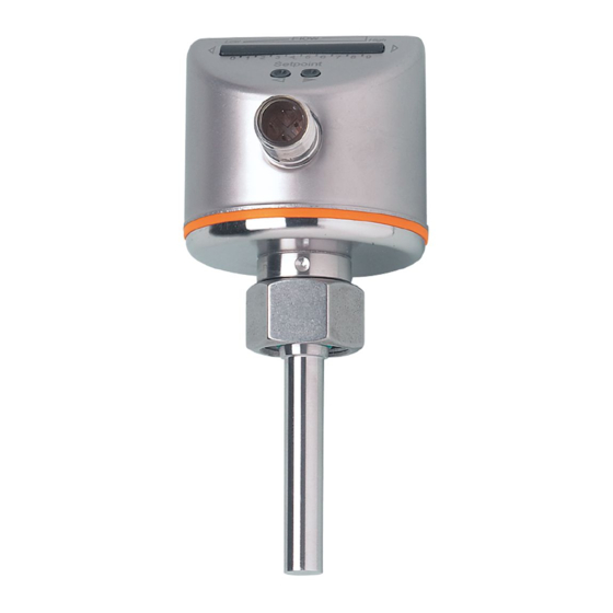
Page 8: Operating And Display Elements
6 Operating and display elements 1: Operating indicators • The green LEDs indicate the current flow (LEDs 0 to 9 represent the range of the monitored flow)� • A lighting LED indicates the position of the switch point (orange = output closed, red = output open)�... -
Page 9: 7�3 Automatic Adjustment (Teach Function)
If no pushbutton is pressed for 2 s, the unit returns to the operating mode with the newly set value� 7.3 Automatic adjustment (Teach function) ► Press the button for at least 15 s� > First the LEDs 0 and 9 light green, then they are flashing green� ►... -
Page 10: Operation
8 Operation In case of power failure or interruption of the operating voltage all settings remain� Operating indicators Current flow below the display range� Current flow below the switch point� Current flow corresponds to the switch point� Current flow above the switch point� Current flow above the display range�... -
Page 11: Maintenance
9 Maintenance Recommended maintenance: ► Check the sensor tip for build-up from time to time� ► Clean it using a soft cloth� Stubborn build-up (e�g� lime) can be removed using a common vinegar cleaning agent�...
Need help?
Do you have a question about the efector 300 SI0558 and is the answer not in the manual?
Questions and answers