
Subscribe to Our Youtube Channel
Related Manuals for Life Fitness Multi-Jungle MJACO


Summary of Contents for Life Fitness Multi-Jungle MJACO
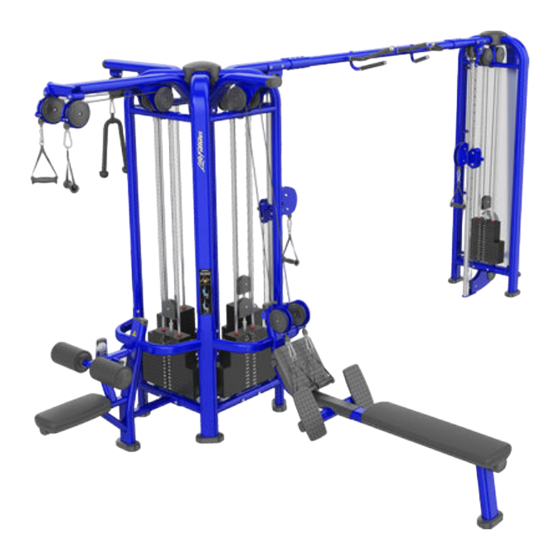
- Page 1 Multi-Jungle MJACO, MJADC, MJAP, MJAP41, MJAXO, MJBLNKSHRD, MJCORE, MJDPH, MJDPL, MJFCO, MJFXO, MJHAR, MJHL, MJLP, MJLPD, MJRW, MJRWD, MJTP Assembly Manual 1007875-0001 REV AA...
-
Page 3: Table Of Contents
Copyright 2017, Life Fitness, LLC. All Rights Reserved. Life Fitness, Hammer Strength, Cybex, ICG and SCIFIT are registered trademarks of Life Fitness, LLC and its affiliated companies and subsidiaries. Disclaimer: Images and specifications are current as of the date of publication and are subject to change. -
Page 4: Safety Information
Safety Information It is the sole responsibility of the purchaser of LIFE FITNESS products to read the owner’s manual and warning labels and instruct all individuals, whether they are the end user or supervising personnel, on proper usage of the equipment. -
Page 5: Selectorized Weight Stack Systems
Selectorized Weight Stack Systems • Use only weight selector pins supplied by LIFE FITNESS on weight stacks. Substitutes are forbidden. • Fully insert weight selector pins. Partial insertion can cause weights to fall unexpectedly. • Never pin the weight stack in an elevated position. -
Page 6: Product Labels
Product Labels General Warning Label Suspension Training Label Serial Number Label Weight At Handle Label Carriage Label Pinch Hazard Label Description Location General Warning Label Tower Frame Suspension Training Label Tower Frame Carriage Label Carriage Serial Number Label Tower Frame and Top or Lower Mount of Stations Weight At Handle Label Top of Weight Stack Pinch Hazard Label... -
Page 7: Assembly
2. Assembly Install Weight Stacks Tools Required: • 5 mm Allen wrench • Retaining ring pliers • Torque wrench NOTE: All screws must be torqued to 25-30 FT-LBS. (27.1-33.9Nm). Description Screw, M10 x 1.5 HXS, 50 mm Guide rod retainer Retaining ring Guide rod Description... - Page 8 Description Guide rod Weight stack Weight Stack Table Description Guide rod retainer Guide rod Description Set screw, M10 x 1.5 HXS, 50 mm Guide rod retainer Retaining ring Guide rod Weight Stack Table Product Weight Stack Weight Plates Attached Cable Crossover (MJACO) 2 x 190 lb./95 kg.
-
Page 9: Install Top Mount
Product Weight Stack Weight Plates Assist Dip Chin (MJADC) 295 lb./147.5 kg. stack 20 lb./9 kg. plate (x19) Adjustable Cable Column (MJAP) 190 lb./91 kg. stack 10 lb./4.5 kg. plate (x6) 15 lb./6.8 kg. plate (x8) Adjustable Pulley 4:1 (MJAP41) 390 lb./195 kg. - Page 10 NOTE: All screws must be torqued to 25-30 FT-LBS. (27.1-33.9Nm). Description Screw, M10 x 1.5, 25 mm Washer Nut, hex nylock Top mount Core Description Screw, M10 x 1.5 HXS, 50 mm Guide rod retainer Retaining ring Guide rod Description Guide rod retainer Guide rod Page 8 of 43...
- Page 11 Description Pulley weldment Guide rod Description Guide rod retainer Guide rod Description Screw, M10 x 1.5 HXS, 50 mm Guide rod retainer Retaining ring Guide rod Page 9 of 43...
- Page 12 Description Screw, M10 x 1.5, 65 mm Washer Nut, hex nylock Pulley weldment Top mount Description Bottom cap cover Page 10 of 43...
-
Page 13: Install Top Mount
Install Top Mount The following procedure shows how to install the top mounts to the MJCORE for the following products: MJAP, MJAP41, MJAXO, MJACO, MJADC, MJFCO, MJFXO, MJHL, MJLP, MJLPD, MJRWD, MJRW, and MJTP. Tools Required: • 7 mm Allen wrench •... - Page 14 Description Bottom cap cover Page 12 of 43...
-
Page 15: Install Lower Mount
Install Lower Mount The following procedure shows how to install the lower mounts to the MJCORE for the following products: MJDPH, MJDPL, MJRWD and MJRW. Tools Required: • 7 mm Allen wrench (x2) • Torque wrench NOTE: All screws must be torqued to 25-30 FT-LBS. (27.1-33.9Nm). Description Screw, M10 x 1.5, 130 mm Washer... - Page 16 • Torque wrench NOTE: All screws must be torqued to 25-30 FT-LBS. (27.1-33.9Nm). Description Lower mount Screw, M10 x 1.5, 130 mm Washer Nut, M10 x 1.5 socket head Description Adjustment tube Nut, M10 x 1.5 socket head Washer Screw, M10 x 1.5, 90 mm Screw, M10 x 1.5, 45 mm Description Adjustment tube...
- Page 17 Description Nut, M10 x 1.5 socket head Washer Screw, M10 x 1.5, 90 mm Screw, M10 x 1.5, 45 mm Description Screw, M10 x 1.5, 130 mm Screw, M10 x 1.5, 60 mm Washer Nut, M10 x 1.5 socket head Adjustment tube bracket Page 15 of 43...
-
Page 18: Install Lower Mount
Install Lower Mount The following procedure shows how to install the lower mounts to the MJCORE for the following products: MJADC. Tools Required: • Retaining ring pliers • 5 mm Allen wrench • 7 mm Allen wrench (x2) • Torque wrench NOTE: All screws must be torqued to 25-30 FT-LBS. - Page 19 Description Guide rod Weight stack cushion Description Screw, M10 x 1.5, 130 mm Washer Nut, M10 x 1.5 socket head Description Short guide rod Weight stack cushion Page 17 of 43...
- Page 20 Description Short guide rod Weight stack Weight Stack Table Description Guide rod retainer Short guide rod Description Set screw, M10 x 1.5 HXS, 50mm Guide rod retainer Retaining ring Short guide rod Page 18 of 43...
-
Page 21: Install Handle Accessory Rack
Install Handle Accessory Rack The following procedure shows how to install the Handle Accessory Rack (MJHAR) to the MJCORE. Tools Required: • 7 mm Allen wrench (x2) • Torque wrench NOTE: All screws must be torqued to 25-30 FT-LBS. (27.1-33.9Nm). Description Screw, M10 x 1.5, 130 mm Washer... -
Page 22: Install Blank Shroud
Install Blank Shroud The following procedure shows how to install the MJBLNKSHRD to the MJCORE. Tools Required: • 7 mm Allen wrench • Torque wrench NOTE: All screws must be torqued to 25-30 FT-LBS. (27.1-33.9Nm). Description Screw, M10 x 1.5, 55 mm Washer Threaded insert Bracket... -
Page 23: Install Front Shroud
Install Front Shroud The following procedure shows how to install the optional front shrouds to the MJCORE. Tools Required: • 5 mm Allen wrench • 7 mm Allen wrench • Retaining ring pliers • Torque wrench NOTE: All screws must be torqued to 25-30 FT-LBS. (27.1-33.9Nm). Description Screw, M10 x 1.5 HXS, 50 mm Guide rod retainer... - Page 24 Description Bracket, bottom Guide rod Weight stack cushion Description Guide rod retainer Guide rod Description Set screw, M10 x 1.5 HXS, 50 mm Guide rod retainer Retaining ring Guide rod Page 22 of 43...
- Page 25 Description Bracket, top left Bracket, top right Description Screw, M10 x 1.5, 20 mm Washer Shroud, left Threaded insert Bracket, top left Description Screw, M10 x 1.5, 20 mm Washer Shroud, left Threaded insert Bracket, bottom 9. Repeat steps 7 and 8 for right shroud. Page 23 of 43...
-
Page 26: Cable Routing
Cable Routing Adjustable Cable Column (MJAP), Adjustable Pulley 4:1 (MJ41), Attached Cable Crossover (MJACO), Embedded Cable Crossover (MJAXO) Page 24 of 43... - Page 27 Assist Dip Chin (MJADC) Page 25 of 43...
- Page 28 Dual Lat Pull (MJLPD) Page 26 of 43...
- Page 29 Dual Pulley High (MJDPH) Page 27 of 43...
- Page 30 Dual Pulley Low (MJDPL) Page 28 of 43...
- Page 31 Dual Row (MJRWD) Page 29 of 43...
- Page 32 High Low (MJHL), Attached High Low Crossover (MJFCO), Embedded High Low Crossover (MJFXO) Page 30 of 43...
- Page 33 Lat Pull (MJLP) Page 31 of 43...
- Page 34 Row (MJRW) Page 32 of 43...
- Page 35 Triceps Pushdown (MJTP) Page 33 of 43...
-
Page 36: Cable Handling Guide
WARNING: Use of non certified “techs” note: Service warranties may be void if a non-Life Fitness-certified technician performs service work. Replacement of any strength cables should be performed by a Life Fitness certified technician. -
Page 37: Cabling Procedure
Cabling Procedure Direct Link 1. Thread the cable into the head plate assembly at least to the jam nut. 2. Cycle the machine to ensure that it is in proper working order. 3. Check the cable to ensure there is proper tension. 4. -
Page 38: Tensioning Cable
8. Tighten the jam nut toward the head plate assembly and frame anchor. 9. Torque the jam nuts to 20-25 FT-LBS. (27.2 - 34.0 Nm). Tensioning Cable Cable should have enough tension so it stays seated into the pulley but not so tight that it pulls the head plate off the weight plate below it. - Page 39 BULGING: Internal wire rope strands can break within and coil causing a bulge to appear. Cable should retain same outside diameter throughout. FRAYED/EXPOSED WIRE ROPE: Any exposed wire rope protruding through the casing or at either end. FLATTENED: Section of cable is compressed and will not retain its shape (outside diameter).
-
Page 40: Bolt To Floor Guide Introduction
4. Bolt to Floor Guide Introduction Life Fitness designs its products to be stable when used as designed. Because strength training is dynamic, we cannot predict how users will ultimately use the products in all circumstances. Therefore, Life Fitness recommends that strength training equipment be secured to a solid, level surface to stabilize and eliminate rocking or tipping over. -
Page 41: Delivery And Installation Tips
Competitor Product The bolt down guidelines and procedures for Life Fitness products were determined by the company’s Engineering and Installation Development groups. These guidelines include which anchors to use and positioning of the anchors are required for Life Fitness product. -
Page 42: Tools Required
Static Anchors Design Resistance in Tension * KH-EZ 1/4” 830 lb (3.6 kN) HUS-H 6mm 3.3 kN (741lb) * Design strength extracted from the Hilti ™ Anchor Fastening Technology Manual. Tools Required WARNING: Adhere to manufacturer’s equipment warnings and guidelines. Follow manufacturer’s instructions for proper usage. -
Page 43: Anchor Procedure
Anchor Procedure 1. Place unit into position to be mounted and cycle unit to set its stance. 2. Wearing protective glasses, drill down into flooring perpendicularly to the required depth, ensuring that the foot thickness of the unit is being accounted for; refer to Anchor Selection and Foot Dimensions. NOTE: Use 3/8"... - Page 44 5. Tighten to 30 foot-pounds for Imperial (45Nm for Metric), assuring there are at least 3 threads left exposed. Item Description Qty. Torque Wrench Anchor Assembly 6. If necessary, cut extra length from top of anchor with a rotary tool leaving proper concrete engagement, torque requirements and at least 3 exposed threads.
-
Page 45: Foot Dimensions
Foot Dimensions Use below images to determine foot height thickness per strength family. Page 43 of 43...
Need help?
Do you have a question about the Multi-Jungle MJACO and is the answer not in the manual?
Questions and answers