
Subscribe to Our Youtube Channel
Related Manuals for Mase VS 10.5


Summary of Contents for Mase VS 10.5
- Page 1 MANUALE USO, MANUTENZIONE E INSTALLAZIONE USE, MAINTENANCE AND INSTALLATION MANUAL 10.5 Rev.3 A.A. 11/02/2020 cod.43598 Tipo modello N° matricola Codice...
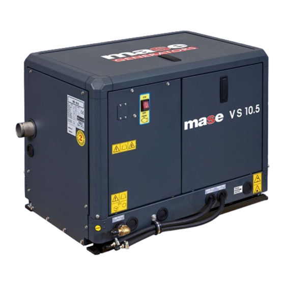
- Page 2 VS 10.5...
- Page 3 VS 10.5 DEFINIZIONI UTILIZZATE - I vocaboli usati sono quelli del linguaggio tecnico corrente e dove si è ritenuto necessario si riportano di seguito il significato - Gruppo elettrogeno E’ l’insieme di un motore a combustione interna a pistoni e un generatore di corrente alternata, uniti tra loro per realizzare una centrale di autoproduzione di energia elettrica.
- Page 4 VS 10.5 - Connessione in cattivo stato Le parti attive non sono completamente ricoperte con un isolamento che possa essere rimosso solo mediante distruzione, le connessioni presentano una incertezza nel collegamento causata da un labile serraggio delle parti e da uno sviluppo di ossido fra le parti.
- Page 5 VS 10.5 PREMESSA CAMPO D’IMPIEGO: IL GRUPPO ELETTROGENO E’ ADATTO A PRODURRE AUTONONAMENTE ENERGIA ELETTRICA NEI LIMITI DI TENSIONE E WATT DICHIARATI DAL COSTRUTTORE, VEDI TARGA CARATTERISTICHE POSTA SULLA MACCHI- Consultare attentamente questo manuale prima di procedere all’uso ed a qualsiasi intervento sulla macchina.
-
Page 6: Informazioni Generali Di Sicurezza
VS 10.5 1 INFORMAZIONI GENERALI DI SICUREZZA 1.1 U SO CONFORME Il gruppo elettrogeno è adatto a produrre autonomamente energia elettrica nei limiti di tensione e potenza dichiarati dal costruttore. E’ vietato ogni altro uso al di fuori del campo di impiego già citato: la macchina è destinata ad un uso marino. -
Page 7: Istruzioni Per La Sicurezza
VS 10.5 ISTRUZIONI PER LA SICUREZZA Le attrezzature elettromeccaniche, inclusi i gruppi generatore, gli interruttori di commutazione, le apparecchiature elettriche di comando, e gli accessori, possono provocare danni alle persone e, qualora vengano installati, utilizzati o siano soggetti a operazioni di manutenzione non idonee, mettere in serio pericolo la vita delle persone stesse. Per evitare incidenti è... - Page 8 VS 10.5 1.4 S IMBOLOGIA SUL GRUPPO ELET TROGENO Cod. 42656 Cod. 42655 Cod. 42653 Cod. 41781 Cod. 42657 Cod.42585 Cod. 42348 Cod. 41779 cod. 42118 Cod. 41763 Cod. 41810...
- Page 9 VS 10.5 1.5 S IGNIFICATO DELLE ETICHET TE DI SICUREZZA • Queste etichette avvertono l’utente su eventuali pericoli che possono causare gravi lesioni. Leggere attentamente il significato e le precauzioni descritte nel presente manuale. • Se l’etichetta si stacca o diventa illeggibile, sostituirla con una nuova richiedendola ad un rivenditore autorizzato.
- Page 10 VS 10.5 Simboli di Pericolo Descrizione PREVENZIONE DA FUOCO Può provocare seri danni o la morte. - Avviare il G.E. solamente dall'interruttore di avviamento senza carichi applicati, con interruttore del gruppo in posizione neutrale. L'avviamento improvviso del gruppo elettrogeno può causare seri infortuni personali.
- Page 11 VS 10.5 Simboli di Pericolo Descrizione GAS DI SCARICO Monossido di carbonio. Utilizzo del gruppo generatore. Il monossido di carbonio può provocare forte nausea, svenimenti, o la morte. Il monossido di carbonio è un gas inodore, incolore, insapore e non irritante, in grado, se inalato anche solo per breve tempo, di provocare la morte.
- Page 12 VS 10.5 Simboli di Pericolo Descrizione BATTERIA Non venire in contatto con il liquido elettrolita della batteria Adeguata ventilazione nella zona batteria. Tenere ben ventilata l'area attorno alla batteria, prestando attenzione a tenere scintille, fiamme libere e altre forme di accensione lontane. Durante il funzionamento del gruppo elettrogeno avviene la ricarica della batteria e la produzione gas idrogeno che può...
- Page 13 VS 10.5 1.6 D 1.8 M OCUMENTI DI RIFERIMENTO ARCATURA Le istruzioni per l'uso fornite con ciascun gruppo elettrogeno La targa predisposta per i gruppi elettrogeni contiene sono costituite da una raccolta di documenti di cui il tutti i dati identificativi in conformità alla norma ISO presente manuale rappresenta la parte generale.
-
Page 14: Caratteristiche Generali
VS 10.5 2 CARATTERISTICHE GENERALI Questo gruppo elettrogeno è destinato ad applicazione nautica. Il generatore è composto da motore Kubota al quale è accoppiato un alternatore a magneti permanenti a giri variabili. Internamente alla cofanatura è installato un inverter AC/AC con tensione in uscita 230V stabilizzata. - Page 15 VS 10.5 2.2 P ANNELLO COMANDI E STRUMENTI A DISTANZA VERSIONE STANDARD Ogni gruppo elettrogeno dispone di un pannello strumenti per i comandi e i controlli sul quale si trovano i seguenti componenti: 1) PULSANTE AVVIO 2) PULSANTE ARRESTO 3) PULSANTE NAVIGAZIONE MENU...
- Page 16 VS 10.5 2.3 T ABELLA CARATTERISTICHE TECNICHE VS 10.5 MODELLO CARATTERISTICHE GENERALI POTENZA CONTINUA (PRP) 10,5 FATTORE DI POTENZA (Cos) TENSIONE NOMINALE 230 / 240 FREQUENZA NOMINALE 50 / 60 GRADO DI PROTEZIONE IP 23 TEMP.MAX DI UTILIZZO °C - °F 40 - 104 TEMP.MIN DI UTILIZZO...
-
Page 17: Installazione
VS 10.5 3 INSTALLAZIONE Il generatore deve essere installato solo da tecnici installatori qualificati. Malfunzionamenti dovuti ad una errata installazione possono causare infortuni o morte. 3.1 C ARATTERISTICHE DEL VANO - Il generatore deve essere installato in un locale sufficientemente areato, in grado di assicurare la quantità minima d'aria necessaria alla combustione del motore. - Page 18 VS 10.5 3.4 V ENTILAZIONE Il generatore è dotato di un sistema interno di raffreddamento forzato attraverso uno scambiatore acqua/aria. La quantità di aria necessaria alla combustione viene aspirata tramite la presa posta sul basamento. Assicurarsi quindi che tale apertura risulti sempre non ostruita.
- Page 19 VS 10.5 3.5.1 S ISTEMA DI ADDUZIONE DELL ACQUA DI MARE I sistemi normalmente adottati sulle imbarcazioni per l'immissione dell'acqua sono due: - Sistema a presa diretta (rif.1). - Sistema con deflettore (rif.2). Il costruttore raccomanda il sistema a presa diretta (rif.1)
- Page 20 VS 10.5 3.5.2 C OMPONENTI Nel caso il gruppo venga installato ad un altezza superiore ad 1m (3,3 ft) sopra la linea di galleggia- mento, è necessario montare una valvola di non ritorno (rif.2) a valle della presa a mare che impe- disce lo svuotamento del circuito acqua a motore spento.
- Page 21 VS 10.5 3.5.3 I NSTALLAZIONI TIPICHE IPICA INSTALLAZIONE CON GRUPPO ELETTROGENO SOPRA LA LINEA DI GALLEGGIAMENTO IPICA INSTALLAZIONE CON GRUPPO ELETTROGENO SOTTO LA LINEA DI GALLEGGIAMENTO - 21...
- Page 22 VS 10.5 IPICA INSTALLAZIONE CON GRUPPO ELETTROGENO CON SEPARATORE SOPRA LA LINEA DI GALLEGGIAMENTO IPICA INSTALLAZIONE CON GRUPPO ELETTROGENO CON SEPARATORE SOTTO LA LINEA DI GALLEGGIAMENTO - 22...
- Page 23 VS 10.5 IPICA INSTALLAZIONE CON GRUPPO ELETTROGENO CON SEPARATORE GENSEP SOPRA LA LINEA DI GALLEGGIAMENTO IPICA INSTALLAZIONE CON GRUPPO ELETTROGENO CON SEPARATORE GENSEP SOTTO LA LINEA DI GALLEGGIAMENTO - 23...
- Page 24 VS 10.5 3.5.4 S ISTEMA DI SCARICO Il sistema di scarico “gas di combustione/acqua” del Marmitta generatore deve essere indipendente da quello dei mo- tori principali dell’imbarcazione. Vedi schemi installazione. La lunghezza del tubo dal punto più alto del condotto di scarico alla marmitta non deve supe- rare 2m (6.6ft).
- Page 25 VS 10.5 3.6 C IRCUITO COMBUST IBILE L'alimentazione del gruppo è a gasolio, ed avviene tramite i raccordi contrassegnati dalle diciture "DIESEL FUEL INLET" (rif.1) e "DIESEL FUEL OUTLET" (rif.2); quest'ultimo serve per il ritorno del combustibile in ecces- I tubi del combustibile devono essere in gomma resistente agli idrocarburi, di diametro interno 6mm (0.26in).
- Page 26 VS 10.5 3.7 C OLLEGAMENTI ELETTRICI 3.7.1 A LLACCIAMENTO BATTERIA Per l'avviamento del gruppo è necessario utilizzare una batteria indipendente a 12V. Essa va allacciata ai morsetti del generatore con cavi di sez. 25mm fino a distanze di 5m (16.4ft) con cavi di sez.
- Page 27 VS 10.5 3.7.2 A LLACCIAMENTO CRUSCOTTO COMANDI Il pannello di avviamento e controllo a distanza (rif.1) deve essere collegato al connettore (rif.2) tramite il cavo di collegamento a corredo. Bloccare il cavo con fascette all’apposito supporto plastico. Quando si eseguono interventi di manutenzione sul...
- Page 28 VS 10.5 3.7.4 A LLACCIAMENTO C Il collegamento alle utenze avviene sulla morsettiera di potenza installata internamente al quadro (rif.1). Cortocircuiti. L’alta tensione può provocare gravi danni o morte. Cortocircuiti possono provocare danni fisici e/o danni alla attrezzatura. Evitare contatti con i collegamenti elettrici tramite attrezzature o gioielleria.
- Page 29 VS 10.5 3.7.5 S CHEDA CONTROLLO MOTORE La scheda controllo motore è provvista di 4 connettori tramite i quali dialoga con scheda inverter e con attuatore per la corretta regolazione dei giri motore. CONNETTORE DESCRIZIONE 1 – giallo GENERATION ON 2 –...
- Page 30 VS 10.5 3.7.6 S CHEDA INVERTER La scheda inverter provvede a controllare e regolare l’onda inarrivo dall’alternatore PMGe stabilizzarne l’uscita al valore alternato di 230V e frequenza 50Hz. cavo scheda controllo (va alla scheda controllo motore nel quadro) cavo di parallelo...
- Page 31 VS 10.5 3.7.7 C OLLEGAMENTO CAVO IN PARALLELO Per il funzionamento in modalità parallela ad un secondo gruppo VS10.5 occorre collegare il cavo dedicato ai connettori CN3 delle rispettive schede inverter. In caso di due batterie dedicate, unire i due cavi dei poli negativi.
-
Page 32: Utilizzo Del Gruppo Elettrogeno
VS 10.5 4 UTILIZZO DEL GRUPPO ELETTROGENO 4.1 C ONTROLLI PRELIMINARI Prima di iniziare qualsiasi procedura di avviamento è estremamente importante "familiarizzare" con il gruppo elettrogeno e i suoi comandi. Si dovrà inoltre eseguire un controllo di sicurezza visivo della macchina e dell'instal- lazione. - Page 33 VS 10.5 4.3 A VVIAMENTO DEL GRUPPO ELETTROGENO Prima di avviare il gruppo elettrogeno assicurarsi che tutti i portelli siano chiusi. Prima di avviare il gruppo accertarsi che i controlli preliminari, descritti al paragrafo 4.1, siano stati ese- guiti. Procedere all’avviamento come spiegato di se- guito.
- Page 34 VS 10.5 4.6 F “ ” UNZIONAMENTO LEPRE In modalità funzionamento automatico, il generatore VS10.5 provvede a regolare automaticamente il regime di rotazione del motore da un minimo di 2100rpm ad un massimo di 3150 rpm in funzione della potenza richiesta dalle utenze, limitando quindi al massimo consumi ed emissioni sonore.
- Page 35 VS 10.5 5 PROTEZIONI E SEGNALAZIONI 5.1 Modulo protezione motore - Allarmi I gruppi elettrogeni sono dotati di una serie di protezioni che li salvaguardano da un utilizzo non corretto e da inconvenienti che ne possono pregiudicare l'integrità. Il modulo CBU (trasferimento dati Can-Bus) gestisce i controlli e i comandi del generatore.
- Page 36 VS 10.5 5.3 P ROTEZIONE DA CORTOCIRCUITO E SOVRACCARICO Il gruppo elettrogeno è protetto da cortocircuito e sovraccarico elettrico. La scheda inverter interrompe l'erogazione della corrente elettrica ed arresta il gruppo elettrogeno al verificarsi di un cortocircuito oppure se la corrente elettrica erogata supera il valore nominale dichiarato.
-
Page 37: Manutenzione
VS 10.5 6 MANUTENZIONE 6.1 P 6.3 C REMESSA ONTROLLO OLIO MOTORE Si raccomanda di seguire scrupolosamente anche le - Controllare il livello dell’olio tramite l’apposito tappo/ indicazioni riportate sul manuale fornito dal Costruttore del astina olio (rif.1). Il livello dell’olio deve sempre essere compreso tra le motore, allegato ad ogni gruppo elettrogeno. - Page 38 VS 10.5 6.4 C AMBIO OLIO MOT ORE Utilizzare olio per motori diesel I rabbocchi e i caricamenti di olio motore vanno eseguiti attraverso il foro (rif.1).Per la sostituzione dell’olio nel carter motore si procede togliendo l’astina di indicazione livello (rif.2).
- Page 39 VS 10.5 Non portare a contatto della pelle il carburante. Durante le operazioni di manutenzione usare guanti e occhiali protettivi. In caso di contatto con carburante lavare immediata- mente e accuratamente la parte con acqua e sapone. Ad operazione ultimata pulire accuratamente tutte le tracce di carburante e versare gli stracci utilizzati presso gli appositi Centri di Raccolta.
- Page 40 VS 10.5 6.9 S VUOTAMENTO IMPIANTO DI RAFFREDDAMENTO Per eseguire la manutenzione sullo scambiatore acqua- Gruppo elettrogeno aria o sull'impianto di raffreddamento è necessario vuotare il circuito di aspirazione dall'acqua di mare. Tale operazione si esegue operando nel seguente modo: - chiudere il rubinetto di presa a mare (rif.1);...
- Page 41 VS 10.5 6.12 M ANUTENZIONE DELLA POMPA ACQUA MARE Almeno una volta all'anno è necessario controllare l'integri- tà della girante in gomma della pompa acqua mare. Prima di aprire la pompa acqua mare per l'ispezione della girante è necessario svuotare l'impianto di raffreddamento dall'acqua di mare come descritto al paragrafo 6.12...
- Page 42 VS 10.5 6.13 C ONT ROLLO SOSTITUZIONE DELLA CINGHIA ALTERNATORE La cinghia è utilizzata per trasmettere il moto di rotazione dalla puleggia dell'albero motore a quella della pompa del liquido a circuito chiuso e dell'alternatore caricabatteria (rif.1). Regolare la tensione della cinghia nel modo seguente: allentare la vite di registro (rif.2) e spostare l'alternatore...
- Page 43 VS 10.5 6.16 L ISTA RICAMBI CONSIGLIATI Girante pompa acqua mare Guarnizione pompa acqua mare Cinghia pompa acqua mare Filtro olio Filtro gasolio Anodi zinco Fusibili E’ disponibile un kit ricambi consigliati, richiedere alla rete assistenza o al servizio assistenza.
- Page 44 VS 10.5 6.18 CONTROLLI PERIODICI E MANUTENZIONE CONTROLLI PERIODICI E MANUTENZIONE Prima Ogni 50 ore Ogni 100 ore Ogni 200 ore Ogni 400 ore o Ogni 500 Manutenzione agli intervalli indicati Ogni 800 ore dell'utilizzo o un mese o 2 mesi...
- Page 45 VS 10.5 6.19 T AVOLA GUASTI Il motorino di avviamento gira ma il motore principale non si avvia. - Verificare la presenza di carburante all’interno del circuito. (Attivare la pompa per ricaricare) - Verificare se l’elettromagnete di stop è in posizione di tiro. (Consultare Centro Assistenza) - Verificare che l’interruttore di emergenza non sia inserito.
- Page 46 VS 10.5 7. TRASPORTO, IMBALLO, STOCCAGGIO, SOLLEVAMENTO E MOVIMENTAZIONE 7.1 T RASPORTO IMBALLO E STOCCAGGIO Imballo: Viene fornito direttamente dalla ditta costruttrice. Il peso totale del gruppo elettrogeno imballato si trova al paragrafo 2.3 “Tabella caratteristiche tecniche”. Trasporto: Durante il trasporto, il gruppo elettrogeno,...
- Page 47 VS 10.5 8 GARANZIA E RESPONSABILITA’ 8.1 G ARANZIA • I Gruppi elettrogeni e tutti i suoi componenti sono garantiti privi di difetti, e sono coperti da garanzia per il periodo previsto dalla normativa vigente, a partire dalla data di acquisto.
-
Page 48: Schemi Elettrici
VS 10.5 10 SCHEMI ELETTRICI - 48... - Page 49 VS 10.5 insulated poles version cod.48914 - 49...
- Page 50 VS 10.5...
-
Page 51: Definitions Used
VS 10.5 DEFINITIONS USED The terms used are current technical terms, and where considered necessary the meaning is described below - Generator An assembly of an internal combustion piston engine and an alternate current generator, joined together to create a station for self-production of electrical energy. - Page 52 VS 10.5 - Connection in bad state The live parts are not fully covered with insulation removable by destruction only, the connections are not secure because of unstable tightening of the parts and a development of oxide between the parts.
-
Page 53: Preliminary Prescriptions
VS 10.5 PRELIMINARY PRESCRIPTIONS FIELD OF EMPLOYMENT: THE GENERATOR IS PROPER FOR TO PRODUCE IN WAY AUTONOMOUS ELECTRIC ENERGY IN THE LIMITS OF TENSION AND WATT DECLARED BY THE BUILDER Consult this manual carefully before proceeding to the use and to any operation on the genset. -
Page 54: General Informations
VS 10.5 1 GENERAL INFORMATIONS 1.1 C ONFORM USE The generator is suitable for independent production of electrical energy within the voltage and wattage limits declared by the manufacturer. Any other use outside the already stated field of use is prohibited: the generator is intended for marine use. -
Page 55: Safety Instructions
VS 10.5 SAFETY INSTRUCTIONS The electromechanics equipments, included the generating sets, switch, command electric equipments and accessories, can cause damages to people and,if they are installed, used or mainteined with not qualified operations, they can put in serious danger the life of people. To avoid accidents is necessary to know the potential risks and operate with caution.Read and follow all the precautions and the instructions for the safety. - Page 56 VS 10.5 1.4 S YMBOLS ON THE GENERAT OR GROUP Cod. 42656 Cod. 42655 Cod. 42653 Cod. 41781 Cod. 42657 Cod.42585 Cod. 42348 Cod. 41779 cod. 42118 Cod. 41763 Cod. 41810...
-
Page 57: Hot Parts
VS 10.5 1.5 S AFET Y LABEL INFORMAT IONS • These labels warn the user of any danger which may cause serious injury. Carefully read the meaning and the precautions described in this manual. • If the label detaches or becomes illegible, replace it with a new one which can be requested from an authorised dealer. -
Page 58: Exhaust System
VS 10.5 Danger Symbols Description PREVENTING FIRE Can cause severe injury or death. • Start • Start the engine only from a starter switch without any load or in neutral posi- tion of the clutch of machine unit. The machine unit suddenly starts to move or generates power to cause serious personal injury. - Page 59 VS 10.5 Danger Symbols Description EXHAUST SYSTEM Carbon monoxide. Group generator use. Carbon monoxide can cause severe nausea, fainting, or death. Carbon monoxide is an odorless, colorless,tasteless, non irritating gas,able to, if inhaled only also for brief time to provoke the death.
-
Page 60: Safety Clothing
VS 10.5 Danger Symbols Description BATTERY Do not touch the electrolitic battery acid Sufficient ventilation of the battery area. • Keep the area around the battery well ventilated, paying attention to keep sparks, open flame and any other form of ignition away. During engine running or charging battery, hydrogen gas is produced from the battery and can be easily ignited. - Page 61 VS 10.5 1.6 R 1.8 M EFERENCE DOCUMENTS ARKING The instructions for use provided with each generator are The generator identification plate carries all the identification made up of a collection of documents of which this manual data conforming to ISO 8528 and in accordance with the represents the General Part.
-
Page 62: General Characteristics
VS 10.5 2 GENERAL CHARACTERISTICS This generator set is designed for nautical application. The generator is composed of a Kubota engine coupled to a variable speed permanent magnet alternator. Inside canopy there is an AC/AC inverter with stabilized 230V output voltage. - Page 63 VS 10.5 2.2 R EMOTE COMMAND AND CONTROL PANEL STANDARD VERSION Each generator is fitted with an instrument panel for commands and controls with the following components: 1) START BUTTON 2) STOP BUTTON 3) MENU NAVIGATION BUTTON 4) MENU NAVIGATION BUTTON...
- Page 64 VS 10.5 2.3 T ECHNICAL CHARACTERISTICS TABLE VS 10.5 MODEL GENERAL FEATURES CONTINUOUS POWER (PRP) 10,5 POWER FACTOR (Cos) RATED VOLTAGE 230 / 240 RATED FREQUENCY 50 / 60 GRADE OF PROTECTION IP 23 MAX TEMP. OF USE °C - °F 40 - 104 MIN TEMP.
-
Page 65: Installation
VS 10.5 3 INSTALLATION The generator may only be installed by qualified technicians. Malfunctioning due to improper installation may cause injury or death. 3.1 G ENERATOR HOUSING CHARACTERISTICS - The generator must be installed in a sufficiently ventilated room able to assure the small amount of air required for engine combustion. - Page 66 VS 10.5 3.4 V ENTILATION The generator is equipped with an internal forced cooling system through a water/air exchanger. The amount of air required for combustion flow through the intake located on the base. Therefore, always check that this intake is free of any obstruction.
- Page 67 VS 10.5 3.5.1 S EA WA TER FEED SYSTEM Two water intake systems are normally adopted on boats: -Direct intake system (ref.1). -System with baffle (ref.2). Manufacturer recommends using the direct intake system (ref.1), since it prevents intake of pressurised water into the intake ducts, instead generating a vacuum easily overcome by the water pump head of the generator.
- Page 68 VS 10.5 3.5.2 C OMPONENTS If the generator is installed at a height over 1m (3,3ft) above the waterline, a check valve (ref.2) must be fitted after the seawater intake to prevent the water circuit from emptying out when the engine is off. If the circuit is empty, the water pump impeller may be damaged during starting.
- Page 69 VS 10.5 3.5.3 T YPICAL NSTALLATIONS YPICAL INSTALLATION WITH GENERATOR ABOVE THE WATERLINE YPICAL INSTALLATION WITH GENERATOR UNDER THE WATERLINE - 21...
- Page 70 VS 10.5 YPICAL INSTALLATION WITH GENERATOR ABOVE THE W ATERLINE WITH WATER GAS SEPARATOR YPICAL INSTALLATION WITH GENERATOR UNDER THE WA TERLINE WITH WATER GAS SEPARATOR - 22...
- Page 71 VS 10.5 YPICAL INSTALLATION WITH GENERATOR ABOVE THE WATERLINE WITH GENSEP WATER GAS SEPARATOR YPICAL INSTALLATION WITH GENERAT OR UNDER THE WATERLINE WITH GENSEP WATER GAS SEPARATOR - 23...
- Page 72 VS 10.5 3.5.4 E XHAUST SYSTEM The generator combustion “gas/water exhaust” system Muffler must be independent of that of the main engines. See installation diagrams. The pipe length from the highest point of the exhaust pipe to the exhaust must not exceed 2m (6.6...
- Page 73 VS 10.5 3.6 F IRCUIT The generator is diesel-powered by means of the unions marked "DIESEL FUEL INLET" (rif.1) e "DIESEL FUEL OUTLET" (rif.2); the latter serves to return excess fuel. The fuel pipes must be in hydrocarbon-resistant rubber with an inside diameter of 6mm (0.24in).
- Page 74 VS 10.5 3.7 E LECTRICAL CONNECTIONS 3.7.1 B A TTERY CONNECTION Use a 12V stand-alone battery to start the generator. Connect it to the generator terminals using cables of 25mm cross-section for a distance up to 5m (16.4ft) cables of 35mm...
- Page 75 VS 10.5 3.7.2 CONTROL PANEL CONNECTION The generator must be connected to the connector (ref.2) to the remote control panel (ref.1) using the supplied cable. Secure the cable to the special plastic band. When carrying out maintenance operations on the generator, disconnect the negative pole of the starter battery to prevent accidental starting.
- Page 76 VS 10.5 3.7.4 A.C. CONNECTION This connection can be made by means of the power terminal board. Connect load to power clamp inside electrical panel (rif.1). Short-circuits. High voltage may cause serious injury or death. Short-circuits may cause physical injury and/or damage to the equipment.
- Page 77 VS 10.5 3.7.5 E NGINE CONTROL MODULE Engine control module communicates with inverter board and with electric actuator for the correct regulation of engine rpm through n.4 connectors. CONNECTOR DESCRIPTION 1 – yellow GENERATION ON 2 – yellow ALARM - OVER TEMPERATURE...
- Page 78 VS 10.5 3.7.6 I NVERTER BOARD Inverterboard controls and adjust electric wave fromPMG alternator and e stabilize output at alternated value of 230V and 50Hz. controller board cable (to rpm controller board inside the control panel) parallel cable (to the inverter on the second...
- Page 79 VS 10.5 3.7.7 P ARALLEL CONNECTION CABLE Connect special cable from CN3 connectors of each inverter board for working in parallel mode with a second VS10.5 generator. In case of two separate batteries, join the two negative pole cables. Simple scheme for operation in parallel mode 3.7.8 G...
-
Page 80: Using The Generator
VS 10.5 4 USING THE GENERATOR 4.1 P RELIMINARY HECKS Before beginning with any starting procedures, it is extremely important to “familiarise” yourself with the generator and its controls. Furthermore, visually inspect the generator and the installation. Any source of real or potential risk must be eliminated before proceeding. - Page 81 VS 10.5 4.3 S TARTING THE GENERATOR Before starting the generator check that all the doors is closed. Before starting the generator ensure that all the preliminary checks, described in paragraph 4.1, have been carried out. Proceed with starting as follow.
- Page 82 VS 10.5 4.6 “HARE” MODE In automatic operation mode, VS10.5 automatically adjusts the engine rpm from a minimum of 2100 rpm to a maximum of 3150 rpm depending on the power required by the users, limiting consumption and noise emissions.
- Page 83 VS 10.5 5 SAFETY SWITCHES AND WARNING SIGNALS Generators are equipped with a set of safety switches which protect against improper use and problems which may cause problems and failures. 5.1 E NGINE PROTECTION MODULE CBU device (Can-Bus transmission unit) controls and driving the genset.
- Page 84 VS 10.5 5.3 P ROTECTION AGAINST SHORT CIRCUITS AND OVERLOAD The generator is protected against shortcircuits and electrical overload. Inverter board breaks current output and stops the generator when short-circuit occours or when output current exceeds the max value. Before start the generator remove the display alarm and the cause of the stop.
-
Page 85: Maintenance
VS 10.5 6 MAINTENANCE 6.1 P 6.3 E REAMBLE NGINE HECK It is strongly recommended to follow also the instructions - Check the oil level by means of the cap/dipstick (ref.1). in the manual provided by engine manufacturer, which is The oil level must always be between the MAX and MIN attached to each generator. - Page 86 VS 10.5 6.4 E NGINE OIL CHANGE Use diesel engine oil Top up the engine oil through the hole (ref.1). To change the oil in the engine oil sump, take out the dipstick (ref.2). Suct exhaust oil with the manual pump (ref.3).
- Page 87 VS 10.5 Do not let the fuel come into contact with the skin. W ea r gl ov es a nd p ro te c ti ve g og gl es d urin g maintenance operations. In the event of contact with fuel, immediately and thoroughly wash the affected part with soap and water.
- Page 88 VS 10.5 DRAINING THE COOLING SYSTEM In order to carry out maintenance on the water/air Genset exchanger or the cooling system, the seawater intake circuit must be drained. Carry out this operation as follows: - close the seawater intake cock (ref.1).
- Page 89 VS 10.5 6.11 S EA WATER PUMP MAINTENANCE At least once a year check the integrity of the rubber seawater pump impeller. Before opening the seawater pump to inspect the impeller, drain the seawater from the cooling system as described in paragraph 6.9.
- Page 90 VS 10.5 6.12 C HECKING REPLACING THE ALTERNATOR V BELT The belt is used to transmit the rotary motion from the drive shaft pulley to the coolant pump and to the battery charger alternator (rif.1). Adjust the belt tension as follows: Loosen the adjusting screw (rif.2) and move the battery...
- Page 91 VS 10.5 6.15 L IST OF RECOMMENDED SPARE PARTS Description Seawater pump impeller Seawater pump gasket Seawater pump belt Oil filter Fuel filter Zinc anode Fuses A kit with recommended spare parts is available and may be ordered from Service Network or Technical Service.
- Page 92 VS 10.5 6.18 P ERIOD CHECKS AND MAINTENANCE Every 50 Every 100 Every 200 Every 400 Before Every Every Perform service at intervals indicated hrs.or 1 hrs.or 2 hrs.or 3 hrs.or starting 500 hrs. 800 hrs. Month Month Month Yearly Fuel system ○...
- Page 93 VS 10.5 6.18 A NOMALIES CAUSES AND REMEDIES The starter motor turns but the main engine does not start - Check that there is fuel in the circuit. (Turn on the fuel pump) - Check if the stop electromagnet is in the firing position. (Consult Service Centre) - Check that the emergency button is in ON position.
-
Page 94: Handling And Packaging
VS 10.5 7 TRANSPORT, STORAGE, LIFTING AND, HANDLING AND PACKAGING 7.1 T RANSPORT AND ST ORAGE customer Packaging: Supplied directly by The total weight of the packed generator is given in Paragraph 2.3 “Table of technical characteristics”. Transport: During transport the generator (with or... -
Page 95: Guarantee And Responsibility
VS 10.5 8 GUARANTEE AND RESPONSIBILITY 8.1 G UARANTEE • Generators and all their components are guaranteed free of defects and are covered by the guarantee for a period as required by current legislation from the date of installation. • Not covered by the guarantee are: failed observance of the installation regulations, damage caused by natural... -
Page 96: Wiring Diagram
VS 10.5 10 WIRING DIAGRAM - 48... - Page 97 VS 10.5 insulated poles version cod.48914 - 49...
- Page 98 Mase Generators S.p.a. • Via Tortona, 345 • 47522 Cesena (FC) ITALY • Tel. (+39) 0547.35.43.11 Fax (+39) 0547.31.75.55 • www.masegenerators.com • e-mail mase@masegenerators.com...
Need help?
Do you have a question about the VS 10.5 and is the answer not in the manual?
Questions and answers