Table of Contents
Advertisement
Quick Links
INSTALLER: Leave this manual with party responsible for use and operation.
OWNER: Retain this manual for future reference.
NOTICE:
DO NOT discard this manual!
Model(s):
WOODBURNING FIREPLACE
Installation and service of this appliance should be performed by
qualified personnel. Hearth & Home Technologies recomends HHT
Factory Trained or NFI certified professionals.
Installation Manual
Installation and Fireplace Setup
Heat & Glo • RH36/RH42 • 4044-194 Installation Manual • Rev R • 01/22
WARNING: If the information in these
instructions is not followed exactly, a fire
or explosion may result causing property
damage, personal injury, or death.
• DO NOT store or use gasoline or other flam-
mable vapors and liquids in the vicinity of this
or any other appliance.
• DO NOT overfire. Overfiring will void your
warranty.
• Comply with all minimum clearances to com-
bustibles as specified. Failure to comply may
cause house fire.
WARNING
HOT SURFACES!
Glass and other surfaces are hot during
operation AND cool down.
Hot glass will cause burns.
• DO NOT touch glass until it is cooled
• NEVER allow children to touch glass
• Keep children away
• CAREFULLY SUPERVISE children in same room as
fireplace.
• Alert children and adults to hazards of high temperatures.
High temperatures may ignite clothing or other flammable
materials.
• Keep clothing, furniture, draperies and other flammable
materials away.
WARNING
Fire Risk.
For use with solid wood fuel only.
Other fuels may overfire and generate
poisonous gases (i.e. carbon monoxide).
1
Advertisement
Table of Contents

Subscribe to Our Youtube Channel
Related Manuals for HEAT GLO RH36


Summary of Contents for HEAT GLO RH36
- Page 1 Factory Trained or NFI certified professionals. WARNING Fire Risk. For use with solid wood fuel only. Other fuels may overfire and generate poisonous gases (i.e. carbon monoxide). Heat & Glo • RH36/RH42 • 4044-194 Installation Manual • Rev R • 01/22...
-
Page 2: Table Of Contents
D. Secure Offset/Return E. Install Ceiling Firestops F. Install Attic Insulation Shield G. Roof Penetration H. Install Chase/Chase Top I. Termination Cap Requirements J. Install Termination Cap Heat & Glo • RH36/RH42 • 4044-194 Installation Manual • Rev R • 01/22... - Page 3 Comments: Further description of the issues, who is responsible (Installer/Builder/Other Trades, etc.) and corrective action needed: Comments communicated to party responsible __________________________ by ______________________on _________ (Builder/Gen. Contractor) (Installer) (Date) 4044-195 • Rev A • 3-28-13 Heat & Glo • RH36/RH42 • 4044-194 Installation Manual • Rev R • 01/22...
-
Page 4: Product Specific & Important Safety Information
State of California to cause birth defects or other reproductive harm. For more information go to: www. P65Warnings.ca.gov. Heat & Glo • RH36/RH42 • 4044-194 Installation Manual • Rev R • 01/22... -
Page 5: Getting Started
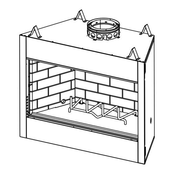
4 ft. Decorative facing (1.22 m) off and trim ground level. Hearth extension Outside combustion air Factory-built fireplace Protective metal hearth strip(s) Figure 2.1 Typical Fireplace System Heat & Glo • RH36/RH42 • 4044-194 Installation Manual • Rev R • 01/22... -
Page 6: Design And Installation Considerations
73 7/8 65 1/2 37 1/4 52 1/4 21 1/2 RH-42 perpendicular wall. 1219 1422 1876 1664 1327 Figure 2.2 Fireplace Locations Heat & Glo • RH36/RH42 • 4044-194 Installation Manual • Rev R • 01/22... -
Page 7: Locating Fireplace & Chimney
• Avoid outside wall Windward Leeward Figure 2.3 Recommended Chimney Locations Not recommended in basement due to high negative pressure concerns that effect draft Heat & Glo • RH36/RH42 • 4044-194 Installation Manual • Rev R • 01/22... -
Page 8: Tools And Supplies Needed
Report to your dealer any parts damaged in shipment. • Read all the instructions before starting the installation. Follow these instructions carefully during the installation to ensure maximum safety and benefit. Heat & Glo • RH36/RH42 • 4044-194 Installation Manual • Rev R • 01/22... -
Page 9: Framing And Clearances
7-1/2 in. 7-1/2 in. 14-1/8 in. (191 mm) (191 mm) (359 mm) Model # 23-3/4 11-7/8 RH-36 1041 29-3/4 14-7/8 RH-42 1067 1194 Figure 3.1 Fireplace Dimensions Heat & Glo • RH36/RH42 • 4044-194 Installation Manual • Rev R • 01/22... -
Page 10: Clearances
1/2 in. (13 mm) to back & sides of appliance 48 in. 1219 mm 0 in. to floor Figure 3.2 Clearances to Combustible Materials Heat & Glo • RH36/RH42 • 4044-194 Installation Manual • Rev R • 01/22... -
Page 11: Construct The Chase
In cold climates, the walls of the chase should be insulated to the level of the false ceiling as shown in Figure 3.3. This will help reduce heat loss from the home around the fireplace. Heat & Glo • RH36/RH42 • 4044-194 Installation Manual • Rev R • 01/22... -
Page 12: Frame The Fireplace
* If interior of chase will be drywalled, add the thickness to ** Adjust header height for a raised floor under fireplace. Figure 3.5 Framing the Fireplace Heat & Glo • RH36/RH42 • 4044-194 Installation Manual • Rev R • 01/22... -
Page 13: Protective Metal Hearth Strips
Raised Platform 2 in. 1 in. (25 mm) min. (51 mm) overlap Floor 2 in. (51 mm) Figure 3.7 Protect the Front of an Elevated Platform Heat & Glo • RH36/RH42 • 4044-194 Installation Manual • Rev R • 01/22... -
Page 14: Outside Air Kit (Optional)
• Secure flex duct with screws or wire ties. Figure 3.8 Outside Air Installation Figure 3.10 Outside Air Installation with Cold Air Trap Heat & Glo • RH36/RH42 • 4044-194 Installation Manual • Rev R • 01/22... -
Page 15: Chimney And Termination Requirements
14.5 ft (4.42 m) min. height/single offset-return 41-1/4 in. 20 ft. (6.10 m) min. height/double offset-return (1048 mm) 90 ft (27.4 m) max. height Effective Height Figure 4.1 Chimney Requirements Heat & Glo • RH36/RH42 • 4044-194 Installation Manual • Rev R • 01/22... -
Page 16: Offsets/Returns
103 1/2 2629 49 1/4 1251 94 1/2 2400 Proper assembly of air-cooled chimney parts result in an overlap at chimney joints of 1-1/4 in. (32 mm). Effective length is built into this chart. Heat & Glo • RH36/RH42 • 4044-194 Installation Manual • Rev R • 01/22... -
Page 17: Termination Requirements
In a staggered installation with both gas and wood terminations, the wood termination cap must be higher than the gas termination cap. Figure 4.3 Multiple Chimney Locations Heat & Glo • RH36/RH42 • 4044-194 Installation Manual • Rev R • 01/22... -
Page 18: Chimney Installation
2 through ceiling or inch clearances. floor Figure 5.1 Typical Chimney System - Guidelines for Chimney System Installation Heat & Glo • RH36/RH42 • 4044-194 Installation Manual • Rev R • 01/22... -
Page 19: Assemble Chimney Sections
Vertical straight runs of chimney must be supported every 35 ft (10.7 m). Figure 5.2 Assembling Chimney Sections WARNING! Risk of Fire! DO NOT install substitute or damaged chimney components. Heat & Glo • RH36/RH42 • 4044-194 Installation Manual • Rev R • 01/22... -
Page 20: Secure Offset/Return
• Use an attic insulation shield if the ceiling is insulated. The ceiling firestop may then be attached above or below the joists. Heat & Glo • RH36/RH42 • 4044-194 Installation Manual • Rev R • 01/22... -
Page 21: Install Attic Insulation Shield
If they have been connected correct- Figure 5.7 Install Attic Insulation Shield (firestop below ceiling) ly, they will not disengage when tested. Heat & Glo • RH36/RH42 • 4044-194 Installation Manual • Rev R • 01/22... -
Page 22: Roof Penetration
WARNING! Risk of Fire! DO NOT caulk the pipe to the chase top collar. • Caulk all seams to prevent leaks. .018 (26 ga) min. Galvanized Chase Top Figure 5.9 Chase Top Construction Heat & Glo • RH36/RH42 • 4044-194 Installation Manual • Rev R • 01/22... -
Page 23: Termination Cap Requirements
Termination cap pipe and chimney section must be snapped together to maintain an overlap of 1-1/2 in. (38 mm). Figure 5.10 Installing a TR344 Round Termination Cap Heat & Glo • RH36/RH42 • 4044-194 Installation Manual • Rev R • 01/22... - Page 24 2 in. (51 mm) Chase Top 4-3/4 in. (121 mm) Chase Chimney Pipe Figure 5.15 Installing a DTO134/DTO146/DTS134/DTS146 Cap Heat & Glo • RH36/RH42 • 4044-194 Installation Manual • Rev R • 01/22...
-
Page 25: Shrouds
3 in (76 mm) air space from bottom of shroud Chase Top to top of chase. Figure 6.3 Shroud & TR Series cap with no Radiation Shield Heat & Glo • RH36/RH42 • 4044-194 Installation Manual • Rev R • 01/22... -
Page 26: Mailbox Style Shroud
Base Dimension 686 x 686 Min. Height Above Bottom of Min. Opening Width Termination Cap Min. Opening Width Min. Opening Height Figure 65 Roofed Style Shroud Dimensions Heat & Glo • RH36/RH42 • 4044-194 Installation Manual • Rev R • 01/22... -
Page 27: Finishing
2 in. (51 mm) ► Figure 7.2 Decorative Facing Heat & Glo • RH36/RH42 • 4044-194 Installation Manual • Rev R • 01/22... -
Page 28: Hearth Extension, Building And Finishing
Marble 14.3-20.0 0.07-0.05 14 5/8 in. - 20 3/8 in. • Choose finishing materials carefully. Model # RH-36 1321 RH-42 1067 1676 Figure 7.3 Hearth Extension Dimensions Heat & Glo • RH36/RH42 • 4044-194 Installation Manual • Rev R • 01/22... -
Page 29: Hearth Extension 4" Or More Below Fireplace Opening
Seal gaps between the hearth extension and the front Figure 7.7 Raised Platform Hearth Extension-Finishing of the fireplace with a bead of non-combustible sealant or grout. Heat & Glo • RH36/RH42 • 4044-194 Installation Manual • Rev R • 01/22... -
Page 30: Fireplace Opening And Hearth Extension Flush
Finished 20 in. Min. Figure 7.9 Place Non-combustible Sealant Floor Hearth Extension Micore Noncombustible Material Protective Metal Hearth Strip Figure 7.8 Flush Hearth Extension Side View Heat & Glo • RH36/RH42 • 4044-194 Installation Manual • Rev R • 01/22... -
Page 31: Mantel And Wall Projections
NOT cover any air sealant to prevent heat from being openings in the face drawn into the wall cavity. of the fireplace. ► Figure 7.10 Mantel Specifications Heat & Glo • RH36/RH42 • 4044-194 Installation Manual • Rev R • 01/22... -
Page 32: Sidewalls/Surrounds
[305 mm] Fireplace Outside Opening Dimensions Model # RH-36 1041 RH-42 1067 1194 Figure 7.11 Mantel Leg, Surround or Wall Projection (acceptable on both sides of opening) Heat & Glo • RH36/RH42 • 4044-194 Installation Manual • Rev R • 01/22... -
Page 33: Fireplace Setup
Repack beyond 4 in. (102 mm) insulation from fireplace side. knockout 4 in. (102 mm) Figure 8.1 Gas Line Installation Heat & Glo • RH36/RH42 • 4044-194 Installation Manual • Rev R • 01/22... -
Page 34: Reference Materials
Field Constructed Shrouds (See “Woodburning Termination Cap”) Storm Collar CT-3A-B Adapter - May be used with the following caps CT Series Attic Shield Kit DT Series Attic Collar Attic Spacer Heat & Glo • RH36/RH42 • 4044-194 Installation Manual • Rev R • 01/22... - Page 35 (305 mm) 10-1/2 in. 24-5/8 in. (267 mm) 31 in. (625 mm) (787 mm) CB876 Chimney Bracket RF371 Roof Flashing TR-TVK - Top Vent Kit CT-3A-B Heat & Glo • RH36/RH42 • 4044-194 Installation Manual • Rev R • 01/22...
- Page 36 TS345/TS345P Square Termination Cap TR342-B Round Telescoping Termination Cap ST375 Square Termination Cap TCT375 Terra Cotta Cap 15-3/4 in. (400 mm) TR344 Round Termination Cap Heat & Glo • RH36/RH42 • 4044-194 Installation Manual • Rev R • 01/22...
- Page 37 DTS134/DTS146 DTO134/DTO146 Decorative Caps DTO134 DTO146 22.7 1168 DTS134 21.18 DTS146 21.18 1168 Heat & Glo • RH36/RH42 • 4044-194 Installation Manual • Rev R • 01/22...
-
Page 38: Optional Components
LDS-BV Decorative Shroud Catalog # 12.5 15.5 LDS-BV Bifold Glass Doors DM1036, DM1042 See your Heat & Glo dealer for a complete list of optional components. Heat & Glo • RH36/RH42 • 4044-194 Installation Manual • Rev R • 01/22... - Page 39 Please contact your Heat & Glo dealer with any questions or concerns. For the location of your nearest Heat & Glo dealer, please visit www.heatnglo.com. Heat & Glo • RH36/RH42 • 4044-194 Installation Manual • Rev R • 01/22...
Need help?
Do you have a question about the RH36 and is the answer not in the manual?
Questions and answers