Advertisement
Quick Links
INSTALLATION AND OPERATION
INSTRUCTIONS
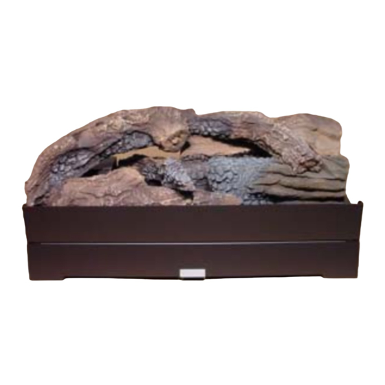
MODEL: GRL-700-AU
AUSTRALIAN GAS ASSOCIATION APPROVED
Approval Number 5669
THIS MANUAL MUST BE USED FOR INSTALLATION AND RETAINED
BY HOMEOWNER FOR OPERATION AND MAINTENANCE.
HEAT & GLO, a brand of Hearth & Home Technologies Inc.
7571 215th Street West, Lakeville, MN 55044, U.S.A. • (952) 985-6000
This product may be covered by one or more of the following patents: (United States) 5328356, 5601073, 5613487,
5647340, 5890485, 5941237, 5947112, 5996575, 6006743, 6019099, 6053165, 6145502, 6170481, 6374822, 6484712,
6601579, 6769426, 6863064, 7077122, 7098269, 7258116, 7470729 or other U.S. and foreign patents pending.
2000-945
1
Heat & Glo • GRL-700-AU • 2010-900 Rev. J • 4/12
Advertisement

Summary of Contents for HEAT GLO GRL-700-AU
- Page 1 This product may be covered by one or more of the following patents: (United States) 5328356, 5601073, 5613487, 5647340, 5890485, 5941237, 5947112, 5996575, 6006743, 6019099, 6053165, 6145502, 6170481, 6374822, 6484712, 6601579, 6769426, 6863064, 7077122, 7098269, 7258116, 7470729 or other U.S. and foreign patents pending. 2000-945 Heat & Glo • GRL-700-AU • 2010-900 Rev. J • 4/12...
- Page 2 Save this Manual for future reference. Copyright 2012 Heat & Glo, a brand of Hearth & Home Technologies Inc. 7571 215th Street West, Lakeville, MN 55044, U.S.A. Printed in U.S.A. Heat & Glo • GRL-700-AU • 2010-900 Rev. J • 4/12...
-
Page 3: Table Of Contents
LOG PLACEMENT ..................7 OPERATING GUIDELINES AND MAINTENANCE INSTRUCTIONS ....10 SAFETY INFORMATION ................11 LIGHTING INSTRUCTIONS ................12 REPLACEMENT PARTS: ................13 WARRANTY POLICY ..................15 = Contains updated information. Heat & Glo • GRL-700-AU • 2010-900 Rev. J • 4/12... - Page 4 FIREPLACE OPENING Minimum Maximum WIDTH: 700 mm 1050 mm DEPTH: 300 mm 460 mm HEIGHT: 425 mm 540 mm FIGURE 1 Heat & Glo • GRL-700-AU • 2010-900 Rev. J • 4/12...
-
Page 5: Introduction
MANUAL. ALL KNOCKOUTS IN THE FIREPLACE THROUGH WHICH THE GAS SUPPLY LINE IS RUN MUST BE RESEALED WITH INSULATION AFTER THE GAS LINE IS IN PLACE. Heat & Glo • GRL-700-AU • 2010-900 Rev. J • 4/12... -
Page 6: Gas Line Connection
NOTE: Appliances incorporating a live fuel effect may lator, a thermopile, a piezo ignitor, and an ON/OFF exhibit slight carbon deposits. rocker switch. For control system wiring diagram see Figure 2. Figure 2 Heat & Glo • GRL-700-AU • 2010-900 Rev. J • 4/12... -
Page 7: Log Placement
Figure 1 NOTE: Overhead view and front view of burner, CAUTION: Logs are fragile. Carefully remove the decorative front and surround. logs from the packaging. Heat & Glo • GRL-700-AU • 2010-900 Rev. J • 4/12... - Page 8 Place log #2 on the right front corner of the unit using its locating slots (on log bottom). STEP 5: LOG #3 (SRV506-717) Place log #3 against the left front corner of log #2 as shown. Heat & Glo • GRL-700-AU • 2010-900 Rev. J • 4/12...
- Page 9 Rest log #5 against log #3 and rest its right edge on log #1. STEP 8: LOG #6 (SRV530-716) Place log #6 in the groove on top of log #2 with its front on log #1. Heat & Glo • GRL-700-AU • 2010-900 Rev. J • 4/12...
-
Page 10: Operating Guidelines And Maintenance Instructions
To obtain proper operation, it is imperative that the pilot and main burner flame characteristics are steady, not lifting or floating. Heat & Glo • GRL-700-AU • 2010-900 Rev. J • 4/12... -
Page 11: Safety Information
• Do not touch any electric switch; do not use any phone in your building. • Immediately call your gas supplier from a neigh- bor’s phone. Follow the gas supplier’s instruc- tions. Heat & Glo • GRL-700-AU • 2010-900 Rev. J • 4/12... -
Page 12: Lighting Instructions
"Pilot" position, then depress knob and continue turning to "OFF" position. 2. Turn ON/OFF switch to "OFF". 4. Replace control access cover. 3. Turn the valve control knob clockwise Heat & Glo • GRL-700-AU • 2010-900 Rev. J • 4/12... - Page 13 GRL-700-AU Service Parts Beginning Manufacturing Date: April 2003 Gas log Set Ending Manufacturing Date: _____ Log Set Assembly Part number list on following page. Heat & Glo • GRL-700-AU • 2010-900 Rev. J • 4/12...
- Page 14 ON/OFF Rocker Switch 060-521A Valve N 060-524 Valve P 060-526 Shut Off Valve 2010-120 060-827A Brass Fitting Mineral Wool 050-721 Touch Up Paint TUP-GBK-12 Wire Assembly 24 In 089-550A Heat & Glo • GRL-700-AU • 2010-900 Rev. J • 4/12...
- Page 15 Conditions, Exclusion, and Limitations listed Igniters, Electronic Components, and Glass 2 years Factory-installed blowers Molded refractory panels 3 years Firepots and burnpots 2000-645 (1-12) Page 1 of 3 Heat & Glo • GRL-700-AU • 2010-900 Rev. J • 4/12...
-
Page 16: Replacement Parts
HHT (8) modifi cation of the appliance not expressly authorized and approved by HHT in writing; and/or (9) interrup- tions or fl uctuations of electrical power supply to the appliance. 2000-645 (1-12) Page 2 of 3 Heat & Glo • GRL-700-AU • 2010-900 Rev. J • 4/12... - Page 17 Jetmaster 444 Swan Street 277 Lord Street 10 Martin Avenue Richmond 3121 East Perth 6000 Arncliff 2205 (03) 9429-5573 (08) 9228-2600 (02) 9597-7222 2000-645 (1-12) Page 3 of 3 Heat & Glo • GRL-700-AU • 2010-900 Rev. J • 4/12...


Need help?
Do you have a question about the GRL-700-AU and is the answer not in the manual?
Questions and answers