
Related Manuals for Miller WC-24


Summary of Contents for Miller WC-24
- Page 1 OM-181 712G 2010−08 Processes MIG (GMAW) Welding Description Weld Control For Spoolmatic Gun WC-24 File: MIG (GMAW) Visit our website at www.MillerWelds.com...
- Page 2 We know you don’t have time to do it any other way. That’s why when Niels Miller first started building arc welders in 1929, he made sure his products offered long-lasting value and superior quality.
-
Page 3: Table Of Contents
TABLE OF CONTENTS SECTION 1 − SAFETY PRECAUTIONS - READ BEFORE USING ........1-1. -
Page 5: Section 1 − Safety Precautions - Read Before Using
SECTION 1 − SAFETY PRECAUTIONS - READ BEFORE USING som _2010−03 Protect yourself and others from injury — read and follow these precautions. 1-1. Symbol Usage DANGER! − Indicates a hazardous situation which, if Indicates special instructions. not avoided, will result in death or serious injury. The possible hazards are shown in the adjoining symbols or explained in the text. - Page 6 D Keep your head out of the fumes. Do not breathe the fumes. D Wear oil-free protective garments such as leather gloves, heavy shirt, cuffless trousers, high shoes, and a cap. D If inside, ventilate the area and/or use local forced ventilation at the arc to remove welding fumes and gases.
-
Page 7: Additional Symbols For Installation, Operation, And Maintenance
1-3. Additional Symbols For Installation, Operation, And Maintenance FIRE OR EXPLOSION hazard. MOVING PARTS can injure. D Do not install or place unit on, over, or near D Keep away from moving parts such as fans. combustible surfaces. D Keep all doors, panels, covers, and guards D Do not install unit near flammables. -
Page 8: California Proposition 65 Warnings
1-4. California Proposition 65 Warnings For Gasoline Engines: Welding or cutting equipment produces fumes or gases which contain chemicals known to the State of California to Engine exhaust contains chemicals known to the State of cause birth defects and, in some cases, cancer. (California California to cause cancer, birth defects, or other reproduc- Health &... -
Page 9: Section 2 − Consignes De Sécurité − Lire Avant Utilisation
SECTION 2 − CONSIGNES DE SÉCURITÉ − LIRE AVANT UTILISATION fre_som_2010−03 Se protéger et protéger les autres contre le risque de blessure — lire et respecter ces consignes. 2-1. Symboles utilisés DANGER! − Indique une situation dangereuse qui si on Indique des instructions spécifiques. - Page 10 Il reste une TENSION DC NON NÉGLIGEABLE dans LE SOUDAGE peut provoquer un les sources de soudage onduleur UNE FOIS incendie ou une explosion. l’alimentation coupée. Le soudage effectué sur des conteneurs fermés tels D Arrêter les convertisseurs, débrancher le courant électrique et que des réservoirs, tambours ou des conduites peut décharger les condensateurs d’alimentation selon les instructions provoquer leur éclatement.
-
Page 11: Dangers Supplémentaires En Relation Avec L'installation, Le Fonctionnement Et La Maintenance
ACCUMULATIONS LES BOUTEILLES peuvent exploser risquent de provoquer des blessures si elles sont endommagées. ou même la mort. Des bouteilles de gaz protecteur contiennent du gaz sous haute pression. Si une bouteille est endom- D Fermer l’alimentation du gaz protecteur en cas magée, elle peut exploser. -
Page 12: Proposition Californienne 65 Avertissements
Les PIÈCES MOBILES peuvent RAYONNEMENT HAUTE causer des blessures. FRÉQUENCE (H.F.) risque provoquer des interférences. D Ne pas s’approcher des organes mobiles. D Ne pas s’approcher des points de coincement D Le rayonnement haute fréquence (H.F.) peut tels que des rouleaux de commande. provoquer des interférences avec les équi- pements de radio−navigation et de com- munication, les services de sécurité... -
Page 13: Principales Normes De Sécurité
2-5. Principales normes de sécurité Safety in Welding, Cutting, and Allied Processes, ANSI Standard Z49.1, 25 West 43rd Street, New York, NY 10036 (téléphone : 212-642-4900, de Global Engineering Documents (téléphone : 1-877-413-5184, site site Internet : www.ansi.org). Internet : www.global.ihs.com). Standard for Fire Prevention During Welding, Cutting, and Other Hot Safe Practices for the Preparation of Containers and Piping for Welding Work, NFPA Standard 51B, de National Fire Protection Association,... - Page 14 OM-181 712 Page 10...
-
Page 15: Section 3 − Definitions
SECTION 3 − DEFINITIONS 3-1. Symbols And Definitions Some symbols are found only on CE products. Output Alternating Current Amperes Volts Degree Of Protec- Single Phase Duty Cycle Hertz tion Conventional Load Read Instructions Percent Primary Voltage Voltage Rated Welding Line Connection Primary Current Current... -
Page 16: Section 4 − Installation
SECTION 4 − INSTALLATION 4-1. Serial Number And Rating Label Location The serial number and rating information for this product is located on the top panel. Use rating label to determine input power requirements and/or rated output. For future reference, write serial number in space provided on back cover of this manual. 4-2. -
Page 17: 14-Pin Plug Information
4-4. 14-Pin Plug Information Pin* Pin Information Contact output signal. Input control to energize weld contactor. Contact closure to A completes 24 volts AC contactor control circuit. Circuit common for 24 volts AC circuit. *The remaining pins are not used. 4-5. -
Page 18: Section 5 − Maintenance & Troubleshooting
SECTION 5 − MAINTENANCE & TROUBLESHOOTING 5-1. Routine Maintenance Disconnect power before maintaining. 3 Months Replace Repair Or Replace Damaged Or Cracked Cord Unreadable Labels 5-2. Troubleshooting Trouble Remedy Pressing gun trigger does not energize Secure plug PLG4 in 14 pin receptacle on welding power source (see Section 4-6). or feed wire. -
Page 19: Section 6 − Electrical Diagrams
SECTION 6 − ELECTRICAL DIAGRAMS 141 989 Figure 6-1. Circuit Diagram OM-181 712 Page 15... -
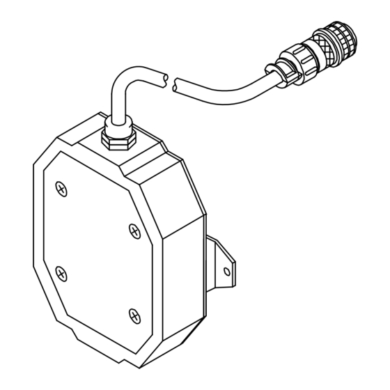
Page 20: Section 7 − Parts List
Dia. Part Description Quantity Mkgs. Figure 7-1. WC-24 Control ....139 042 Bushing, Strain Relief .270/.480 Id X .804Mtg Hole .... - Page 21 Notes Start Your Professional Over 80,000 trained 400 Trade Square East, Troy, Ohio 45373 Welding Career Now! since 1930! 1-800-332-9448 www.welding.org...
- Page 22 Notes SOCKET/WRENCH SELECTION TABLE SOCKET/WRENCH SELECTION TABLE (U.S. STANDARD) (METRIC) Specifications Socket or Wrench Size Specifications Socket or Wrench Size U.S. Bolt Decimal Bolt Bolt Decimal Bolt Diameter Equivalent Diameter Equivalent 1/4 in .250 in 3/8 in 7/16 in 6 mm .2362 in 10 mm 10 mm...
- Page 23 Effective January 1, 2010 (Equipment with a serial number preface of MA or newer) This limited warranty supersedes all previous Miller warranties and is exclusive with no other Warranty Questions? guarantees or warranties expressed or implied. LIMITED WARRANTY − Subject to the terms and conditions 90 Days —...
- Page 24 Contact the Delivering Carrier to: File a claim for loss or damage during shipment. For assistance in filing or settling claims, contact your distributor and/or equipment manufacturer’s Transportation Department. © ORIGINAL INSTRUCTIONS − PRINTED IN USA 2010 Miller Electric Mfg. Co. 2010−01...
Need help?
Do you have a question about the WC-24 and is the answer not in the manual?
Questions and answers