Table of Contents
Advertisement
For product information,
Owner's Manual translations,
and more, visit
www.MillerWelds.com
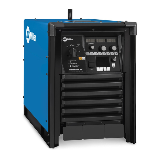
Auto−Continuum
350 And 500
w/ Insight Coret
OM-273473D
Processes
Processes
MIG (GMAW) Welding
Pulsed MIG (GMAW-P)
Flux Cored (FCAW) Welding
Air Carbon Arc (CAC-A)
Cutting and Gouging
Description
Arc Welding Power Source
File: Advanced Manufacturing Systems
2016−11
®
Advertisement
Table of Contents
Troubleshooting

Subscribe to Our Youtube Channel
Related Manuals for Miller Auto-Continuum 350


Summary of Contents for Miller Auto-Continuum 350
- Page 1 OM-273473D 2016−11 Processes Processes MIG (GMAW) Welding Pulsed MIG (GMAW-P) Flux Cored (FCAW) Welding Air Carbon Arc (CAC-A) Cutting and Gouging Description Arc Welding Power Source ® Auto−Continuum 350 And 500 w/ Insight Coret For product information, File: Advanced Manufacturing Systems Owner’s Manual translations, and more, visit www.MillerWelds.com...
- Page 2 We know you don’t have time to do it any other way. That’s why when Niels Miller first started building arc welders in 1929, he made sure his products offered long-lasting value and superior quality.
-
Page 3: Table Of Contents
TABLE OF CONTENTS SECTION 1 − SAFETY PRECAUTIONS - READ BEFORE USING ....... . . 1-1. - Page 4 TABLE OF CONTENTS SECTION 7 − OPERATION ..............7-1.
-
Page 5: Section 1 − Safety Precautions - Read Before Using
SECTION 1 − SAFETY PRECAUTIONS - READ BEFORE USING som 2015−09 Protect yourself and others from injury — read, follow, and save these important safety precautions and operating instructions. 1-1. Symbol Usage DANGER! − Indicates a hazardous situation which, if Indicates special instructions. - Page 6 D Remove stick electrode from holder or cut off welding wire at FUMES AND GASES can be hazardous. contact tip when not in use. D Wear body protection made from durable, flame−resistant material Welding produces fumes and gases. Breathing (leather, heavy cotton, wool). Body protection includes oil-free these fumes and gases can be hazardous to your clothing such as leather gloves, heavy shirt, cuffless trousers, high health.
-
Page 7: Additional Symbols For Installation, Operation, And Maintenance
1-3. Additional Symbols For Installation, Operation, And Maintenance FIRE OR EXPLOSION hazard. MOVING PARTS can injure. D Do not install or place unit on, over, or near D Keep away from moving parts such as fans. combustible surfaces. D Keep all doors, panels, covers, and guards D Do not install unit near flammables. -
Page 8: California Proposition 65 Warnings
1-4. California Proposition 65 Warnings Welding or cutting equipment produces fumes or gases This product contains chemicals, including lead, known to which contain chemicals known to the State of California to the state of California to cause cancer, birth defects, or other cause birth defects and, in some cases, cancer. -
Page 9: Section 2 − Consignes De Sécurité − Lire Avant Utilisation
SECTION 2 − CONSIGNES DE SÉCURITÉ − LIRE AVANT UTILISATION fre_som_2015−09 Pour écarter les risques de blessure pour vous−même et pour autrui — lire, appliquer et ranger en lieu sûr ces consignes relatives aux précautions de sécurité et au mode opératoire. 2-1. - Page 10 chauffement ou un incendie. Avant de commencer le soudage, vérifier LES PIÈCES CHAUDES peuvent et s’assurer que l’endroit ne présente pas de danger. provoquer des brûlures. D Déplacer toutes les substances inflammables à une distance de D Ne pas toucher à mains nues les parties chaudes. 10,7 m de l’arc de soudage.
-
Page 11: Dangers Supplémentaires En Relation Avec L'installation, Le Fonctionnement Et La Maintenance
D Tenir les bouteilles éloignées des circuits de soudage ou autres LE BRUIT peut endommager l’ouïe. circuits électriques. D Ne jamais placer une torche de soudage sur une bouteille à gaz. Le bruit des processus et des équipements peut affecter l’ouïe. D Une électrode de soudage ne doit jamais entrer en contact avec D Porter des protections approuvées pour les une bouteille. -
Page 12: Proposition Californienne 65 Avertissements
RAYONNEMENT HAUTE LE SOUDAGE À L’ARC risque de FRÉQUENCE (H.F.) risque provoquer des interférences. provoquer des interférences. D L’énergie électromagnétique risque D Le rayonnement haute fréquence (H.F.) peut provoquer des interférences pour l’équipement provoquer des interférences avec les équi- électronique sensible tel que les ordinateurs et l’équipement commandé... -
Page 13: Section 3 − Definitions
SECTION 3 − DEFINITIONS 3-1. Additional Safety Symbols And Definitions Some symbols are found only on CE products. Warning! Watch Out! There are possible hazards as shown by the symbols. Safe1 2012−05 Wear dry insulating gloves. Do not touch electrode with bare hand. Do not wear wet or damaged gloves. Safe2 2012−05 Protect yourself from electric shock by insulating yourself from work and ground. - Page 14 Do not remove or paint over (cover) the label. Safe20 2012−05 When power is applied failed parts can explode or cause other parts to explode. Safe26 2012−05 Flying pieces of parts can cause injury. Always wear a face shield when servicing unit. Safe27 2012−05 Always wear long sleeves and button your collar when servicing unit.
-
Page 15: Miscellaneous Symbols And Definitions
3-2. Miscellaneous Symbols And Definitions Some symbols are found only on CE products. Rated Maximum Voltage 1max Supply Current Primary Voltage Purge By Gas Degree Of Protection Voltage Input Locked Suitable for Some Hazardous Protective Earth Locations (Ground) Process Maximum Effective 1eff Supply Current Arc Force... -
Page 16: Section 4 − Specifications
SECTION 4 − SPECIFICATIONS 4-1. Serial Number And Rating Label Location The serial number and rating information for this product is located on the back. Use rating label to determine input power requirements and/or rated output. For future reference, write serial number in space provided on back cover of this manual. 4-2. -
Page 17: Dimensions And Weight
4-4. Dimensions And Weight Hole Layout Dimensions *27-3/16 in. 17-33/64 in. (445 mm) **28−7/32 in. (691 mm) (717 mm) 17-3/8 in. (441 mm) 26-11/64 in. (665 mm) 16-3/32 in. (409 mm) 2-9/32 in. (58 mm) 24-57/64 in. (632 mm) 15/32 in. (12 mm) 15/32 x 1 in. -
Page 18: Duty Cycle And Overheating
4-7. Duty Cycle And Overheating Duty Cycle is percentage of 10 min- 350 Model utes that unit can weld at rated load without overheating. If unit overheats, thermostat(s) opens, output stops, and cooling fan runs. Wait fifteen minutes for unit to cool. Reduce amperage or duty cycle before welding. -
Page 19: Section 5 − Installation
SECTION 5 − INSTALLATION 5-1. Selecting A Location Movement Do not move or operate unit where it could tip. Location And Airflow Special installation may be required where gasoline or volatile liquids are present − see NEC Article 511 or CEC Section 20. -
Page 20: Weld Output Terminals And Selecting Cable Sizes
**Weld cable size (AWG) is based on either a 4 volts or less drop or a current density of at least 300 circular mils per ampere. ( ) = mm for metric use ***For distances longer than those shown in this guide, call a factory applications rep. at 920-735-4505 (Miller) or 1-800-332-3281 (Hobart). Ref. S-0007-L 2015−02 OM-273473 Page 16... -
Page 21: Connecting Weld Output Cables
5-3. Connecting Weld Output Cables Turn off power before connecting to weld output tabs or receptacles. Tools Needed: 3/4 in. (19 mm) for output Do not use worn, damaged, under- terminal type connection sized, or repaired cables. Failure to properly connect weld cables may cause excessive heat and start a fire, or damage your machine. -
Page 22: Remote 10 Wire Feeder Control Receptacle Rc2 Information
5-4. Remote 10 Wire Feeder Control Receptacle RC2 Information Socket Socket Information +50 Volts DC Common +50 Volts DC Common Voltage Sense +50 Volts DC Power +50 Volts DC Power ENET Rx − ENET Tx − Drain ENET Tx + ENET Rx + 907 657-tp2 5-5. -
Page 23: Peripheral Receptacle Rc22 Functions
5-6. Peripheral Receptacle RC22 Functions Socket Socket Information Output common Digital output 1 (DO1) Digital output 2 (DO2) Digital output 3 (DO3) Not Used Chassis ground Input common Request to turn on Touch Sense (DI1) Digital input 2 (DI2) Digital input 3 (DI3) Not Used Not Used Touched hardware signal... -
Page 24: Aux Power And Cb2 (Optional)
5-8. Aux Power And CB2 (Optional) 115 V AC Receptacle Supplementory Protector CB2 CB2 protects 115 V AC receptacle. Press button to reset breaker. If breaker continues to open, contact a Factory Authorized Service Agent. Ref. 907641−TP1 / 907657-tp2 5-9. Devicenet Receptacle Socket Socket Information Chassis ground. -
Page 25: Electrical Service Guide
5-10. Electrical Service Guide Elec Serv 2014−01 Failure to follow these electrical service guide recommendations could create an electric shock or fire hazard. These recommendations are for a dedicated circuit sized for the rated output and duty cycle of the welding power source. In dedicated circuit installations, the National Electrical Code (NEC) allows the receptacle or conductor rating to be less than the rating of the circuit protection device. -
Page 26: Connecting 3-Phase Input Power
5-11. Connecting 3-Phase Input Power L1 (U) L2 (V) L3 (W) = GND/PE Earth Ground Input Power Contactor Connections Side View Of Unit Tools Needed: 3/8 in. 3/16 in. input5 2013−04 / 274300-B / 259119-C OM-273473 Page 22... - Page 27 5-11. Connecting 3-Phase Input Power (Continued) Input Power Conductors (Customer Input Conductors L1, L2, L3 Installation must meet all National and Supplied Cord) Local Codes − have only qualified per- Connect input conductors L1, L2, and L3 to sons make this installation. Select size and length of conductors using welding power source line terminals.
-
Page 28: Section 6 − Recommended Setup Procedures
SECTION 6 − RECOMMENDED SETUP PROCEDURES 6-1. Welding Circuit Minimizing the welding circuit loop can prevent extreme voltage drops that produce poor welding characteristics. Welding Power Source Appearance of actual unit may differ from that shown. Electrode Cable Feeder Cable Standard Welding Circuit Work Cable Voltage Sensing Lead... -
Page 29: Arranging Welding Cables To Reduce Welding Circuit Inductance
6-2. Arranging Welding Cables To Reduce Welding Circuit Inductance Welding Power Source Appearance of actual unit may differ from that shown. Electrode Cable Feeder Cable Work Cable Voltage Sensing Lead Robot Workpiece The arrangement of the cables has an effect that is significant to the welding properties. -
Page 30: Using Multiple Welding Power Sources
6-3. Using Multiple Welding Power Sources Appearance of actual unit may differ from that shown. Travel Current Flow Path 250 504-B Welding Power Source possible, but not in the return current path. Arc blow occurs primarily during the welding of steel or ferromagnetic metals. Electrode Cable Connect voltage sensing lead at the end of Weld current will take the path of least... -
Page 31: Voltage Sensing Lead And Work Cable Connections For Multiple Welding Arcs
6-4. Voltage Sensing Lead And Work Cable Connections For Multiple Welding Arcs A. Bad Setup Appearance of actual unit may differ from that shown. Current Flow Path 250 512-B Welding Power Source Workpiece across the workpiece will not be measured correctly for the voltage feedback signal. - Page 32 B. Better Setup Appearance of actual unit may differ from that shown. Current Flow Path 250 513-B Welding Power Source Robot the welding power sources. The most accurate voltage sensing may not be Electrode Cable Workpiece achieved due to voltage drops in the Feeder Cable workpiece.
- Page 33 C. Best Setup Appearance of actual unit may differ from that shown. Current Flow Path 250 515-B Welding Power Source Voltage Sensing Lead This arrangement is the best setup for proper voltage sensing at the workpiece. Electrode Cable Robot Voltage feedback to the welding power Feeder Cable sources will more accurate and result in Work Cable...
-
Page 34: Earth Grounding
6-5. Earth Grounding When using a robot or any programmable controls, it is necessary to connect equipment to a good earth ground. Grounding helps eliminate electrically generated noise from corrupting processing data or the potential damage to sensitive electrical components. Electrical noise is an issue anytime high frequency TIG equipment or inverter type power supplies are used in the area. - Page 35 OM-273473 Page 31...
-
Page 36: Points Of Mechanics In Mig Welding
6-6. 30 Points Of Mechanics In MIG Welding 30 Pts MIG − 2014-09 Primary Power Check primary power connection at line disconnect switch or receptacle and/or cord plug. Check primary power connection at welding power source. Secondary Power Check secondary weld output connections at welding power source. Inspect condition and routing of positive weld cable to wire drive motor. -
Page 37: Arc Blow
6-7. Arc Blow Arc blow is the deflection of the welding arc from its normal path due to magnetic forces. This condition is usually encountered in direct current welding of magnetic materials, such as iron and nickel. Arc blow can happen in alternating current welding under certain conditions, but these cases are rare and the intensity of the arc blow is always less severe. -
Page 38: Basic Welding Troubleshooting
6-8. Basic Welding Troubleshooting Listed below are some problems, causes and remedies related to welding operations; however, this list does not contain every possible condition that could be encountered in welding. Trouble Probable Cause Remedy No weld output; unit completely Line disconnect switch in Off position. - Page 39 Trouble Probable Cause Remedy Porosity in weld. Dirty base metal, heavy oxides, mill scale, oil, etc. Clean base metal by brushing, grinding or use chemical cleansing before welding. Regulator/flowmeter faulty. Adjust or replace regulator/flowmeter. Gas cylinder valve closed. Open gas cylinder valve. Gas regulator diaphragm defective.
- Page 40 Trouble Probable Cause Remedy Wandering, hunting or erratic arc. Restriction in unspooler or drum adapter. Replace unspooler or repair restriction. Dirty or worn gun liner or inlet cable. Remove gun liner or inlet cable and clean or re- place. Sharp bends or kinks in gun cable or liner. Straighten gun cable and/or replace liner.
-
Page 41: Section 7 − Operation
SECTION 7 − OPERATION 7-1. Operator Controls Power Switch Turns unit On or Off. Power On LED Power LED illuminates when unit is energized. Output On LED Output LED illuminates when weld output is energized. Error LED On Solid− Unit has overheated and weld out- put has been disabled. -
Page 42: User Interface
7-2. User Interface Ref. 266 061-B OM-273473 Page 38... -
Page 43: Description Of Front Panel Controls (See Section 7-2)
7-3. Description Of Front Panel Controls (See Section 7-2) Memory Display button. Press the button to select options 13 Voltage Indicator available in the LCD display The Memory display shows the active weld LED illuminates to show that the voltage Values/Parameters LCD Display program. -
Page 44: Section 8 − Configuration
SECTION 8 − CONFIGURATION 8-1. Accessing Configuration Web Pages To access the power source configuration webpages you will need the optional communication panel (See Section 5-7). Connect a PC directly to the jack on the communication panel with a CAT5 or CAT6 Ethernet cable. Enter the default IP address, 169.254.0.2, into a web browser and the welder configuration web pages will open to the Home screen. -
Page 45: Setup Screen
8-3. Setup Screen Information Bar Data Connections 11 Wire Spool Displays general information on welding pow- Displays which data connections are enabled Displays wire type, spool size, and amount of er source, location, asset number, serial num- or disabled. wire remaining on the spool. Edit button allows ber, and display language. -
Page 46: Arc Management Screen
8-4. Arc Management Screen Active Program Weld Sequence Program Enable Displays the program number, process, wire Displays active weld sequence parameters. Edit button will allow user to select which pro- size and alloy, and gas. Edit button allows Edit button allows changes to these parame- grams are available for use. -
Page 47: Data Management Screen
8-5. Data Management Screen Productivity Factory Reset button will take user to a Facto- System Log ry Reset screen. Read and follow all instruc- Displays tarc time and wire used in inches and Displays the last entry into the system log. tions on Factory Reset screen to perform a pounds. -
Page 48: Section 9 − Maintenance & Troubleshooting
SECTION 9 − MAINTENANCE & TROUBLESHOOTING 9-1. Routine Maintenance Disconnect power Maintain more often before maintaining. during severe conditions. n = Check Z = Change ~ = Clean l = Replace Reference * To be done by Factory Authorized Service Agent l Unreadable Labels ~ Weld Terminals nl Weld Cables... -
Page 49: Error Code Troubleshooting Description And Tables
9-3. Error Code Troubleshooting Description And Tables STUK ERROR Button on UI stuck Make sure all buttons are clear If error persists, please contact support. Logs Ref. 266 061-B LED Display Message ERROR- The system has experienced a LCD Display Message fault that must be addressed before contin- Provides more information about the mes- uing use. - Page 50 LED Display Message LCD Solution LCD Error Log LCD Display Message Message Type Message Message WELD WAIT ERROR Unit was not ready for a weld se- Press button to clear error Weld Wait Error quence ERR OVERTEMP ERROR Welding power source has overheated Allow unit too cool then cycle Overtemp Error power...
- Page 51 LED Display Message LCD Solution LCD Error Log LCD Display Message Message Type Message Message ERR BTN STUK ERROR Button on UI stuck Make sure all buttons are UI Button Stuck clear ERR COMM UI ERROR UI Lost Comms to the Sequencer Check the control cable UI lost comms to Seq FACTORY RST...
- Page 52 LED Display Message LCD Solution LCD Error Log LCD Display Message Message Type Message Message ERR PWR SRC ERROR Boost fault Cycle power on the power Boost Fault Error source ERR PWR SRC ERROR Boost contactor error Cycle power on the power Boost Contactor Error source ERR PWR SRC...
-
Page 53: Troubleshooting
9-4. Troubleshooting Trouble Remedy No weld output; completely inoperative Place line disconnect in On position (see Section 5-11). Check and replace line fuse(s), if necessary, or reset circuit breaker (see Section 5-11). Check for proper input power connections (see Section 5-11). No weld output;... -
Page 54: Section 10 − Electrical Diagrams
SECTION 10 − ELECTRICAL DIAGRAMS Figure 10-1. Circuit Diagram For Auto-Contiuum 350 Model (Page 1 of 2) OM-273473 Page 50... - Page 55 273 905-B OM-273473 Page 51...
- Page 56 Figure 10-2. Circuit Diagram For Auto-Continuum 350 Model (Page 2 of 2) OM-273473 Page 52...
- Page 57 273 905-B OM-273473 Page 53...
- Page 58 Figure 10-3. Circuit Diagram For Auto-Contiuum 500 Model (Page 1 of 2) OM-273473 Page 54...
- Page 59 273 490-B OM-273473 Page 55...
- Page 60 Figure 10-4. Circuit Diagram For Auto-Continuum 500 Model (Page 2 of 2) OM-273473 Page 56...
- Page 61 273 490-B OM-273473 Page 57...
-
Page 62: Section 11 − Parts List For 350 And 500 Models
SECTION 11 − PARTS LIST FOR 350 AND 500 MODELS Figure 11-7 Figure 11-6 Figure 11-2 Figure 11-3 Figure 11-4 Figure 11-5 274585-B Figure 11-1. Main Assembly OM-273473 Page 58... - Page 63 Item Dia. Part Mkgs. Description Quantity Figure 11-1. Main Assembly Model Model ... . . +265236 Base ,Continuum .........
- Page 64 Hardware is common and not available unless listed. Ref. 269 780-C Figure 11-2. Right-Hand Windtunnel w/Components Item Dia. Part Mkgs. Description Quantity Figure 11-2. Right-Hand Windtunnel w/Components (Figure 11-1, Item 14) Model Model ....265243 Windtunnel, Rh .
- Page 65 Hardware is common and not available unless listed. 269 781-A Figure 11-3. Left-Hand Windtunnel w/Components Item Dia. Part Mkgs. Description Quantity Figure 11-3. Left-Hand Windtunnel w/Components (Figure 11-1, Item 15) Model Model ..L1-L4 ..252375 Inductor, Input .
- Page 66 Hardware is common and not available unless listed. 269 782-B Figure 11-4. Fan Panel Assembly Item Dia. Part Mkgs. Description Quantity Figure 11-4. Fan Panel Assembly (Figure 11-1, Item 8) ....265241 Panel, Fan Motor .
- Page 67 Notes OM-273473 Page 63...
- Page 68 Hardware is common and not available unless listed. 274588A Figure 11-5. Front Panel Assembly OM-273473 Page 64...
- Page 69 Item Dia. Part Description Quantity Mkgs. Figure 11-5. Front Panel Assembly (Figure 11-1, Items 7, 9) ....252825 Bezel, Upper ........... .
- Page 70 Hardware is common and not available unless listed. 269784-C Figure 11-6. Penthouse Assembly Item Dia. Part Description Quantity Mkgs. Figure 11-6. Penthouse Assembly (Figure 11-1, Item 12) ....245520 Bushing, Snap-in Nyl 1.062 Id X 1.500 Mtg Hole Cent .
- Page 71 Hardware is common and not available unless listed. Ref. 274590C Figure 11-7. Rear Panel Assembly Item Dia. Part Description Quantity Mkgs. Figure 11-7. Rear Panel Assembly (Figure 11-1, Item 5) ... . . +273395 Panel, Rear .
- Page 72 Notes...
- Page 73 Notes...
- Page 74 Notes...
- Page 75 Effective January 1, 2016 (Equipment with a serial number preface of MG or newer) This limited warranty supersedes all previous Miller warranties and is exclusive with no other guarantees or warranties expressed or implied. Warranty Questions? LIMITED WARRANTY − Subject to the terms and conditions below, 6 Months —...
- Page 76 Contact the Delivering Carrier to: File a claim for loss or damage during shipment. For assistance in filing or settling claims, contact your distributor and/or equipment manufacturer’s Transportation Department. © ORIGINAL INSTRUCTIONS − PRINTED IN USA 2016 Miller Electric Mfg. Co. 2016−01...
Need help?
Do you have a question about the Auto-Continuum 350 and is the answer not in the manual?
Questions and answers