Table of Contents
Troubleshooting

Subscribe to Our Youtube Channel
Related Manuals for Miller Multimatic 220


Summary of Contents for Miller Multimatic 220
- Page 1 OM-281426D 2023-07 Processes Multiprocess Welding Description Arc Welding Power Source And Wire Feeder Multimatic ® AC/DC OWNER’S MANUAL For product information, Owner’s Manual translations, and more, visit www.MillerWelds.com...
- Page 2 We know you don’t have time to do it any other way. That’s why when Niels Miller first started building arc welders in 1929, he made sure his products offered long-lasting value and superior quality.
-
Page 3: Table Of Contents
TABLE OF CONTENTS SECTION 1 – SAFETY PRECAUTIONS – READ BEFORE USING..............1 Symbol Usage . - Page 4 TABLE OF CONTENTS 6-16 Factory Reset (Menu 8 Of 12) ..................42 6-17 Display Software (Menu 9 Of 12) .
-
Page 5: Section 1 - Safety Precautions - Read Before Using
SECTION 1 – SAFETY PRECAUTIONS – READ BEFORE USING Protect yourself and others from injury—read, follow, and save these important safety precautions and operating instructions. 1-1. Symbol Usage DANGER! – Indicates a hazardous situation which, if not avoided, will result in death or serious injury. The possible hazards are shown in the adjoining symbols or explained in the text. - Page 6 HOT PARTS can burn. WELDING can cause fire or explosion. � Do not touch hot parts bare handed. � Allow cooling period before working on equipment. Welding on closed containers, such as tanks, drums, or pipes, can cause them to blow up. �...
-
Page 7: Additional Hazards For Installation, Operation, And Maintenance
� Never weld on a pressurized cylinder—explosion will result. CYLINDERS can explode if � Use only correct compressed gas cylinders, regulators, hoses, damaged. and fittings designed for the specific application; maintain them Compressed gas cylinders contain gas under high and associated parts in good condition. pressure. -
Page 8: California Proposition 65 Warnings
� To reduce possible interference, keep weld cables as short as ARC WELDING can cause possible, close together, and down low, such as on the floor. interference. � Locate welding operation 100 meters from any sensitive electronic equipment. � Electromagnetic energy can interfere with sensitive electronic equipment such as microprocessors, �... -
Page 9: Section 2 - Consignes De Sécurité - Lire Avant Utilisation
SECTION 2 – CONSIGNES DE SÉCURITÉ - LIRE AVANT UTILISATION Pour écarter les risques de blessure pour vous-même et pour autrui — lire, appliquer et ranger en lieu sûr ces consignes relatives aux précautions de sécurité et au mode opératoire. 2-1. - Page 10 � S’assurer que tous les panneaux et couvercles sont correctement LES ACCUMULATIONS DE GAZ en place. risquent de provoquer des blessures � Fixer le câble de retour de façon à obtenir un bon contact métal- ou même la mort. métal avec la pièce à souder ou la table de travail, le plus près possible de la soudure.
-
Page 11: Symboles De Dangers Supplémentaires En Relation Avec L'installation, Le Fonctionnement Et La Maintenance
� Brancher le câble de masse sur la pièce le plus près possible de � Les porteurs d’implants médicaux doivent consulter leur médecin la zone de soudage pour éviter le transport du courant sur une lon- et le fabricant du dispositif avant de s’approcher de la zone où se gue distance par des chemins inconnus éventuels en provoquant déroule du soudage à... - Page 12 � Affûter l'électrode au tungstène uniquement à la meuleuse dotée LIRE LES INSTRUCTIONS. de protecteurs. Cette manœuvre est à exécuter dans un endroit sûr lorsque l'on porte l'équipement homologué de protection du vi- � Lire et appliquer les instructions sur les étiquettes sage, des mains et du corps.
-
Page 13: Proposition Californienne 65 Avertissements
2-4. Proposition californienne 65 Avertissements AVERTISSEMENT – Ce produit peut vous exposer à des pro- Pour plus d’informations, consulter www.P65Warnings.ca.gov. duits chimiques tels que le plomb, reconnus par l’État de Californie comme cancérigènes et sources de malforma- tions ou d’autres troubles de la reproduction. 2-5. -
Page 14: Section 3 - Definitions
� Complete Parts List is available at www.MillerWelds.com SECTION 3 – DEFINITIONS Safe75 201 Do not fuel a hot engine. 3-1. Additional Safety Symbol Definitions Safe24 20 Warning! Watch Out! There are possible hazards as shown by the symbols. Safe82 201 Use lift eye to lift unit and properly installed accessories only, not gas cylinders. - Page 15 � Complete Parts List is available at www.MillerWelds.com Shielded Metal Arc Lift-Arc (GTAW) TIG Welding (SMAW) Gas Postflow / Remote Electrode Holder Wire Feed Slow Gas Metal Arc Gas Preflow Run In Welding (GMAW) Gas Metal Arc Cold Jog (Inch) To- Work Connection Welding (GMAW) ward Workpiece...
-
Page 16: Section 4 - Specifications
Information About Default Weld Parameters And Settings NOTICE – Each welding application is unique. Although certain Miller Electric products are designed to determine and default to certain typical welding parameters and settings based upon specific and relatively limited application variables input by the end user, such default settings are for reference purposes only;... -
Page 17: Environmental Specifications
� Complete Parts List is available at www.MillerWelds.com 4-7. Environmental Specifications A. IP Rating IP Rating IP21 This equipment is designed for indoor use and is not intended to be used or stored outside. B. Temperature Specifications Operating Temperature Range* Storage/Transportation Temperature Range 14 to 104°F (-10 to 40°C) -4 to 131°F (-20 to 55°C) -
Page 18: Duty Cycle And Overheating For Mig (Gmaw)
A complete Parts List is available at www.MillerWelds.com 1-4. Duty Cycle And Overheating For MIG (GMAW) � Complete Parts List is available at www.MillerWelds.com 4-9. Duty Cycle And Overheating For MIG (GMAW) Duty Cycle is percentage of 10 minutes that unit weld rated... -
Page 19: Duty Cycle And Overheating For Tig (Gtaw)
A complete Parts List is available at www.MillerWelds.com � Complete Parts List is available at www.MillerWelds.com 1-5. Duty Cycle And Overheating For TIG (GTAW) 4-10. Duty Cycle And Overheating For TIG (GTAW) Duty Cycle is percentage of 10 minutes that unit weld rated... -
Page 20: Duty Cycle And Overheating For Stick (Smaw)
� Complete Parts List is available at www.MillerWelds.com A complete Parts List is available at www.MillerWelds.com 4-11. Duty Cycle And Overheating For Stick (SMAW) 1-6. Duty Cycle And Overheating For Stick (SMAW) Duty Cycle is percentage of 10 minutes that unit weld rated... -
Page 21: Section 5 - Installation
� Complete Parts List is available at www.MillerWelds.com SECTION 5 – INSTALLATION 5-1. Selecting A Location Do not move or operate unit where Movement it could tip. Special installation may be re- quired where gasoline or volatile liquids are present - see NEC Ar- ticle 511 or CEC Section 20. -
Page 22: Multi-Voltage Plug (Mvp) Connection
� Complete Parts List is available at www.MillerWelds.com 5-2. Multi-Voltage Plug (MVP) Connection Selecting Plug Connecting Plug To Power Cord Ref. 803812-C Ref. 803812-C 2 Plug - NEMA Type 5-15P Connecting Plug To Power Cord Do not cut off power cord connector and rewire. -
Page 23: Electrical Service Guide
� Complete Parts List is available at www.MillerWelds.com 5-3. Electrical Service Guide Failure to follow these electrical service guide recommendations could create an electric shock or fire hazard. These recommen- dations are for an individual branch circuit sized for the rated output and duty cycle of one welding power source. In individual branch circuit installations, the National Electrical Code (NEC) allows the receptacle or conductor rating to be less than the rating of the circuit protection device. -
Page 24: Connecting 120 Volt Input Power
� Complete Parts List is available at www.MillerWelds.com 5-5. Connecting 120 Volt Input Power Input6 2011 03 275173A / Ref. 805 474-A NOTICE – The Auto-Line circuitry in this unit time-delay fuses or circuit breaker is Installation must meet all National automatically links the power source to the required. -
Page 25: Connecting 1-Phase Input Power For 240 Vac
� A complete Parts List is available at www.MillerWelds.com Complete Parts List is available at www.MillerWelds.com 5-6. Connecting 1-Phase Input Power For 240 VAC Connecting 1-Phase Input Power For 240 VAC Installation must meet all National and Local Codes—have only quali- fied persons make this installation. -
Page 26: Generator Requirements
2-4. Generator / Inverter Requirements � Complete Parts List is available at www.MillerWelds.com 5-7. Generator Requirements Engine Control Switch must be set Generator settings, if applicable at "RUN" position - not "RUN/ IDLE". Set generator Fine Adjustment Control to 10 for maximum auxili- ary power. -
Page 27: Stick Welding Connections
� Complete Parts List is available at www.MillerWelds.com 5-8. Stick Welding Connections Turn off unit and disconnect input power before making connections. Do not use worn, damaged, under- sized, or repaired cables. 1 Weld Output Receptacle 2 Work Clamp Receptacle 3 Stick Electrode Holder And Cable 4 Work Clamp And Cable Connect stick electrode holder cable to the... -
Page 28: Tig Welding Connections
� Complete Parts List is available at www.MillerWelds.com 5-9. TIG Welding Connections Turn off unit and disconnect input power before making connections. Do not use worn, damaged, under- sized, or repaired cables. 1 Weld Output Receptacle 2 Work Clamp Receptacle 3 TIG Torch And Cable 4 Work Clamp And Cable Connect TIG torch cable to the electrode re-... -
Page 29: Mig Welding Connections
� Complete Parts List is available at www.MillerWelds.com 5-10. MIG Welding Connections A complete Parts List is available at www.MillerWelds.com Ref. 275172A / Ref. 275167A / Ref. 275168A Ensure all connections are tight. Route trigger control cable through MIG gun Turn off unit and disconnect input hole. -
Page 30: Mig Gun Connection Inside Unit
� Complete Parts List is available at www.MillerWelds.com 5-11. MIG Gun Connection Inside Unit 1 Gun Securing Knob 2 Gun Block 3 Gun Outlet Wire Guide 4 Gun End Loosen knob. Insert end of gun through opening in front panel until gun end bot- toms against gun block. -
Page 31: Connecting Shielding Gas Supply
� Complete Parts List is available at www.MillerWelds.com 5-12. Connecting Shielding Gas Supply Obtain gas cylinder and chain to running gear, wall, or other stationary support so cyl- inder cannot fall and break off valve. 1 Cap 2 Cylinder Valve Remove cap, stand to side of valve, and open valve slightly. -
Page 32: Installing Wire Spool And Adjusting Hub Tension
A complete Parts List is available at www.MillerWelds.com 2-10. Installing Wire Spool And Adjusting Hub Tension � Complete Parts List is available at www.MillerWelds.com 2-10. Installing Wire Spool And Adjusting Hub Tension 5-13. Installing Wire Spool And Adjusting Hub Tension A complete Parts List is available at www.MillerWelds.com 2-10. -
Page 33: Threading Welding Wire
� Complete Parts List is available at www.MillerWelds.com 5-14. Threading Welding Wire Warning 6 in. (150 mm) Warning Warning Tighten philips head wrench crescent wrench Warning Tighten nutdriver chippinghammer WOOD Step 6. Turn On. uty workclamp wirecutter frontcutter 1 Wire Spool �... -
Page 34: Removing Mig Gun To Replace With A Spool Gun
� Complete Parts List is available at www.MillerWelds.com 5-15. Removing MIG Gun To Replace With A Spool Gun A complete Parts List is available at www.MillerWelds.com 2-12. Removing MIG Gun To Replace With A Spool Gun Warning tools/ allen_set flathead philips head wrench crescent wrench... -
Page 35: Section 6 - Operation
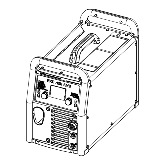
� Complete Parts List is available at www.MillerWelds.com SECTION 6 – OPERATION 6-1. Controls Rear View 1 Process Select Buttons 7 TIG Arc Start Select Buttons � When MIG Aluminum process is se- Press the up and down buttons to select de- lected, Wire/Rod/Tungsten buttons are Press the up and down buttons to select de- used to select type of spool gun being... -
Page 36: Controls, Tig Aluminum Manual Mode
� A complete Parts List is available at www.MillerWelds.com Complete Parts List is available at www.MillerWelds.com 6-2. Controls, TIG Aluminum Manual Mode 3-2. Controls, TIG Aluminum Manual Mode 1 Auto-Set Button Press button to turn Auto-Set feature On or Off. Auto-Set is On when illuminated. 2 Tungsten Size Buttons Press the Plus (+) or Minus (-) button to ad- just up or down. -
Page 37: Controls, Tig Steel/Stainless Manual Mode
� A complete Parts List is available at www.MillerWelds.com Complete Parts List is available at www.MillerWelds.com 6-3. Controls, TIG Steel/Stainless Manual Mode 3-3. Controls, TIG Steel/Stainless Manual Mode 1 Auto-Set Button A complete Parts List is available at www.MillerWelds.com Press button to turn Auto-Set feature On or Off. -
Page 38: Controls, Mig Manual Mode
� A complete Parts List is available at www.MillerWelds.com Complete Parts List is available at www.MillerWelds.com 6-5. Controls, MIG Manual Mode 3-5. Controls, MIG Manual Mode 1 Auto-Set Button Press button to turn Auto-Set feature On or Off. Auto-Set is On when illuminated. 2 Volts Adjustment Knob 3 Wire Feed Speed Adjustment Knob Ref. -
Page 39: Welding Parameter Chart-120V
� Complete Parts List is available at www.MillerWelds.com 6-6. Welding Parameter Chart—120V Steel WireWelding (MIG/Flux−Cored) Parameters 120 Volt Shielding 3/16” 24 ga 20 ga 16 ga 1/8” 1/4” 22 ga 18 ga 14 ga Gas* Material Polarity Wire Type Wire Size (V/WFS) (V/WFS) (V/WFS) -
Page 40: Welding Parameter Chart-240V
� Complete Parts List is available at www.MillerWelds.com 6-7. Welding Parameter Chart—240V Steel WireWelding (MIG/Flux−Cored) Parameters 240 Volt Shielding 3/16” 24 ga 20 ga 16 ga 1/8” 1/4” 3/8” 22 ga 18 ga 14 ga 5/16” Material Polarity Gas* Wire Type Wire Size (V/WFS) (V/WFS) (V/WFS) -
Page 41: Entering Setup Menu
A complete Parts List is available at www.MillerWelds.com � Complete Parts List is available at www.MillerWelds.com 6-8. Entering Setup Menu Ref. 281252A Minus (-) button and Material Thickness To move to the previous setup menu, press 1 Wire/Rod/Tungsten Minus (-) Button Plus (+) button. -
Page 42: Internal Motor 24 Inch Calibration (Menu 1 Of 12)
� Complete Parts List is available at www.MillerWelds.com A complete Parts List is available at www.MillerWelds.com 6-9. Internal Motor 24 Inch Calibration (Menu 1 Of 12) 3-9. Internal Motor 24 Inch Calibration (Menu 1 Of 12) A complete Parts List is available at www.MillerWelds.com 3-9. -
Page 43: Spoolmate
Motor calibration is necessary any time a different Spoolmate 100 or 150 is connected to the Multimatic 220. Connect Spoolmate to unit. Cut wire flush at nozzle. Follow instructions in Section 6-8 to enter the setup menu. -
Page 44: Spoolmate Run-In Speed (Menu 4 Of 12)
� Ref. 281252A Complete Parts List is available at www.MillerWelds.com 6-12. Spoolmate Run-In Speed (Menu 4 Of 12) 3-12. Spoolmate Run-In Speed (Menu 4 Of 12) 1 Wire/Rod/Tungsten Minus (-) Button 2 Auto-Set Button 3 Material Thickness Minus (+) Button Follow instructions in Section 6-8 to enter the setup menu. -
Page 45: Primary Logs (Menu 6 Of 12)
� Complete Parts List is available at www.MillerWelds.com A complete Parts List is available at www.MillerWelds.com A complete Parts List is available at www.MillerWelds.com 6-14. Primary Logs (Menu 6 Of 12) 3-14. Primary Logs (Menu 6 Of 12) 3-14. Primary Logs (Menu 6 Of 12) 1 Material Thickness Minus (-) Button 2 Material Thickness Plus (+) Button Follow instructions in Section 6-8 to enter... -
Page 46: Factory Reset (Menu 8 Of 12)
� Complete Parts List is available at www.MillerWelds.com A complete Parts List is available at www.MillerWelds.com 6-16. Factory Reset (Menu 8 Of 12) 3-16. Factory Reset (Menu 8 Of 12) 1 Material Thickness Minus (-) Button 2 Material Thickness Plus (+) Button 3 Auto-Set Button �... -
Page 47: Control Software (Menu 10 Of 12)
3-18. Control Software (Menu 10 Of 12) 3-18. Control Software (Menu 10 Of 12) � Complete Parts List is available at www.MillerWelds.com 6-18. Control Software (Menu 10 Of 12) � Control Software information is for fac- tory and service use only. The displays that are shown are for reference only. -
Page 48: Tig Postflow Control (Menu 12 Of 12)
� Complete Parts List is available at www.MillerWelds.com A complete Parts List is available at www.MillerWelds.com 6-20. TIG Postflow Control (Menu 12 Of 12) 3-19. TIG Postflow Control (Menu 12 Of 12) 1 Wire/Rod/Tungsten Minus (-) Button 2 Auto-Set Button 3 Material Thickness Plus (+) Button 4 Right Encoder Follow instructions in Section 6-8 to enter... -
Page 49: Section 7 - Maintenance And Troubleshooting
� Complete Parts List is available at www.MillerWelds.com SECTION 7 – MAINTENANCE AND TROUBLESHOOTING Complete Parts List is available at www.MillerWelds.com 7-1. Routine Maintenance Disconnect power before maintaining. � Maintain more often during severe conditions. � = Check ◇ = Change �... -
Page 50: Changing Drive Roll Or Wire Inlet Guide
� Complete Parts List is available at www.MillerWelds.com 7-3. Changing Drive Roll Or Wire Inlet Guide 1 Inlet Wire Guide Remove guide by pressing on barbed area or cutting off one end near housing and pull- ing it out of hole. Push new guide into hole from rear until it snaps in place. -
Page 51: Error Messages
Wait for unit to cool down. If the fan is not run- er cools down. maximum limit. ning, contact Miller Electric Mfg. service dept. Shorted trigger-Release 4-pin trigger MIG gun or spool gun trigger is engaged on Release 4-pin trigger to clear error. -
Page 52: Troubleshooting
Boost error-Cycle power to clear error. The primary boost has not successfully been Cycle power to clear error. If this error persists established. after a power cycle, contact Miller Electric Mfg. LLC service department. Over voltage-Cycle power to clear. Primary voltage is above 310 volts. -
Page 53: Section 8 - Parts List
� Complete Parts List is available at www.MillerWelds.com SECTION 8 – PARTS LIST 8-1. Recommended MIG Spare Parts Recommended Spare Parts Dia. Mkgs. Part No. Description Quantity 261167 Roll, Drive .024, .030–.035V Wire, .035VK Wire 202926 Roll, Drive VK .030–.035/.045 Wire 271493 Lens Cover, Replaceable ♦Optional... -
Page 54: Section 9 - Electrical Diagrams
SECTION 9 – ELECTRICAL DIAGRAMS Figure 9-1. Circuit Diagram OM-281426 Page 50... - Page 55 281418-A OM-281426 Page 51...
-
Page 56: Section 10 - High Frequency
SECTION 10 – HIGH FREQUENCY SECTION 1 HIGH FREQUENCY 10-1. Welding Processes Requiring High Frequency SECTION 1 HIGH FREQUENCY 1 High-Frequency Voltage TIG – helps arc jump air gap between torch and workpiece and/or stabilize the arc. 10-2. Installation Showing Possible Sources Of HF Interference 11, 12 Best Practices Not Followed 11, 12... -
Page 57: Recommended Installation To Reduce Hf Interference
10-3. Recommended Installation To Reduce HF Interference Best Practices Followed 50 ft (15 m) 50 ft (15 m) 1 High-Frequency Source (welding power Conduit Joint Bonding and Grounding Ground workpiece if required by codes. source with built-in HF or separate HF Electrically join (bond) all conduit sections 9 Nonmetal Building unit) -
Page 58: Section 11 - Selecting And Preparing A Tungsten For Dc Or Ac Welding With Inverter Machines
SECTION 11 – SELECTING AND PREPARING A TUNGSTEN FOR DC OR AC WELDING WITH INVERTER MACHINES 11-1. Selecting Tungsten Electrode Whenever possible and practical, use DC weld output instead of AC weld output. NOTICE – Wear clean gloves to prevent contamination of tungsten. A. -
Page 59: Preparing Tungsten Electrode For Dc Electrode Negative (Dcen) Welding Or Ac Welding With Inverter Machines
1-1. Preparing Tungsten Electrode For DC Electrode Negative (DCEN) Welding Or AC Welding With Inverter Machines Grinding the tungsten electrode produces dust and flying sparks which can cause injury and start fires. 11-2. Preparing Tungsten Electrode For DC Electrode Negative (DCEN) Welding Or AC Use local exhaust (forced ventilation) at the grinder or wear an approved respirator. -
Page 60: Section 12 - Gmaw Welding (Mig) Guidelines
SECTION 12 – GMAW WELDING (MIG) GUIDELINES 12-1. Typical GMAW (MIG) Process Connections 1 Wire Feeder/Welding Power Source 5 Gas Weld current can damage electronic parts in vehicles. Disconnect both 2 Gun 6 Shielding Gas battery cables before welding on a 3 Workpiece vehicle. - Page 61 Wire Size Amperage Range Recommended Wire Feed Speed Wire Feed Speed * 0.023 in. (0.58 mm) 30-90 A 3.5 in. (89 mm) per amp 3.5 x 62.5 A = 219 ipm (5.56 mpm) 0.030 in. (0.76 mm) 40-145 A 2 in. (51 mm) per amp 2 x 62.5 A = 125 ipm (3.19 mpm) 0.035 in.
- Page 62 12-4. Conditions That Affect Weld Bead Shape Gun Angles and Weld Bead Profiles � Weld bead shape depends on gun an- gle, direction of travel, electrode exten- sion (stickout), travel speed, thickness of base metal, wire feed speed (weld current), and voltage. 1 Push 2 Perpendicular 3 Drag...
- Page 63 12-5. Gun Movement During Welding � Normally, a single stringer bead is sat- isfactory for most narrow groove weld joints; however, for wide groove weld joints or bridging across gaps, a weave bead or multiple stringer beads works better. 1 Stringer Bead - Steady Movement Along Seam 2 Weave Bead - Side To Side Movement Along Seam...
- Page 64 12-8. Troubleshooting – Excessive Spatter Excessive Spatter - scattering of molten metal particles that cool to solid form near weld bead. Possible Causes Corrective Actions Wire feed speed too high. Select lower wire feed speed. Voltage too high. Select lower voltage range. Electrode extension (stickout) too long.
- Page 65 12-11. Troubleshooting – Lack Of Penetration Lack Of Penetration - shallow fusion between weld metal and base metal. Possible Causes Corrective Actions Improper joint preparation. Material too thick. Joint preparation and design must provide access to bottom of groove while maintaining proper welding wire extension and arc characteristics.
- Page 66 12-15. Troubleshooting – Distortion Distortion - contraction of weld metal during welding that forces base metal to move. Illustration: Base metal moves in the direction of the weld bead. Possible Causes Corrective Actions Excessive heat input. Use restraint (clamp) to hold base metal in position. Make tack welds along joint before starting welding operation.
-
Page 67: Troubleshooting Guide For Semiautomatic Welding Equipment
12-17. Troubleshooting Guide For Semiautomatic Welding Equipment Problem Probable Cause Remedy Wire feed motor operates, but wire does not Too little pressure on wire feed rolls. Increase pressure setting on wire feed rolls. feed. Incorrect wire feed rolls. Check size stamped on wire feed rolls, re- place to match wire size and type if necessary. -
Page 68: Section 13 - Stick Welding (Smaw) Guidelines
SECTION 13 – STICK WELDING (SMAW) GUIDELINES tools/ 13-1. Stick Welding Procedure wrench crescent wrench allen_set flathead philips head wrench crescent wrench Weld current starts when electrode Tools Needed: touches workpiece. Weld current can damage elec- tronic parts in vehicles. Discon- nect both battery cables before welding on a vehicle. - Page 69 13-2. Electrode And Amperage Selection Chart 6010 DEEP 3/32 MIN. PREP, ROUGH HIGH SPATTER 6011 DEEP 6010 5/32 & 6013 EP,EN GENERAL 3/16 6011 7/32 SMOOTH, EASY, 7014 EP,EN FAST 1/16 LOW HYDROGEN, 7018 5/64 STRONG 3/32 FLAT SMOOTH, EASY, 7024 EP,EN 6013...
- Page 70 13-4. Positioning Electrode Holder 1 End View Of Work Angle Groove Welds 2 Side View Of Electrode Angle After learning to start and hold an arc, prac- tice running beads of weld metal on flat 10 -30 10 -30 plates using a full electrode. Hold the electrode nearly perpendicular to the work, although tilting it ahead (in the di- rection of travel) will be helpful.
- Page 71 13-7. Conditions That Affect Weld Bead Shape Electrode Angle � Weld bead shape is affected by elec- trode angle, arc length, travel speed, and thickness of base metal. 1 Angle Too Small 2 Correct Angle 3 Drag 4 Angle Too Large 5 Too Short 6 Normal Arc Length...
- Page 72 13-9. Welding Lap Joints 1-1. Welding Lap Joints 1 Electrode 2 Single-Layer Fillet Weld 1-1. Welding Lap Joints Move electrode in circular motion. 3 Multi-Layer Fillet Weld Weld a second layer when a heavier fillet is needed. Remove slag before making anoth- er weld pass.
- Page 73 13-11. Welding T-Joints 1-3. Welding T-Joints 1/16 in. (1.6 mm) 1 Electrode 2 Fillet Weld Keep arc short and move at definite rate of speed. Hold electrode as shown to provide fusion into the corner. Square edge of the weld surface. For maximum strength weld both sides of up- 1-3.
- Page 74 Excessive Spatter - scattering of molten metal particles that cool to solid form near weld bead. Possible Causes Corrective Actions Amperage too high for electrode. Decrease amperage or select larger electrode. Arc length too long or voltage too high. Reduce arc length or voltage. Incomplete Fusion - failure of weld metal to fuse completely with base metal or a preceding weld bead.
- Page 75 Distortion - contraction of weld metal during welding that forces base metal to move. Illustration: Base metal moves in the direction of the weld bead. Possible Causes Corrective Actions Excessive heat input. Use restraint (clamp) to hold base metal in position. Make tack welds along joint before starting welding operation.
- Page 76 Notes...
- Page 77 Notes...
- Page 78 Notes...
- Page 79 Effective January 1, 2023 (Equipment with a serial number preface of ND or newer) This limited warranty supersedes all previous Miller warranties and is exclusive with no other guarantees or war- ranties expressed or implied. � CoolBelt, PAPR Blower, and PAPR Face...
- Page 80 Appleton, WI 54914 USA tact your distributor and/or equipment manu- facturer’s Transportation Department. International Headquarters–USA USA Phone: 920-735-4505 USA & Canada FAX: 920-735-4134 International FAX: 920-735-4125 For International Locations Visit www.MillerWelds.com ORIGINAL INSTRUCTIONS – PRINTED IN USA © Miller Electric Mfg. LLC 2023-07...
Need help?
Do you have a question about the Multimatic 220 and is the answer not in the manual?
Questions and answers
How do I reset to factory settings?