Table of Contents
Troubleshooting

Related Manuals for Miller WC-115A


Summary of Contents for Miller WC-115A
- Page 1 OM-1078 142862S 2022−11 Processes MIG (GMAW) Welding Description Weld Control For Spoolmatic Gun WC−115A For product information, File: MIG (GMAW) Owner’s Manual translations, and more, visit www.MillerWelds.com...
- Page 2 We know you don’t have time to do it any other way. That’s why when Niels Miller first started building arc welders in 1929, he made sure his products offered long-lasting value and superior quality.
-
Page 3: Table Of Contents
TABLE OF CONTENTS SECTION 1 − SAFETY PRECAUTIONS - READ BEFORE USING ....... . . 1-1. -
Page 5: Section 1 − Safety Precautions - Read Before Using
SECTION 1 − SAFETY PRECAUTIONS - READ BEFORE USING som 2022−01 Protect yourself and others from injury — read, follow, and save these important safety precautions and operating instructions. 1-1. Symbol Usage DANGER! − Indicates a hazardous situation which, if Indicates special instructions. - Page 6 D Be aware that welding on a ceiling, floor, bulkhead, or partition can FUMES AND GASES can be hazardous. cause fire on the hidden side. D Do not cut or weld on tire rims or wheels. Tires can explode if heat- ed.
-
Page 7: Additional Hazards For Installation, Operation, And Maintenance
D Never weld on a pressurized cylinder − explosion will result. CYLINDERS can explode if damaged. D Use only correct compressed gas cylinders, regulators, hoses, and fittings designed for the specific application; maintain them Compressed gas cylinders contain gas under high and associated parts in good condition. -
Page 8: California Proposition 65 Warnings
H.F. RADIATION can cause interference. ARC WELDING can cause interference. D High-frequency (H.F.) can interfere with radio D Electromagnetic energy can interfere with navigation, safety services, computers, and sensitive electronic equipment such as communications equipment. computers and computer-driven equipment such as robots. D Have only qualified persons familiar with electronic equipment D Be sure all equipment in the welding area is electromagnetically perform this installation. -
Page 9: Section 2 − Consignes De Sécurité − Lire Avant Utilisation
SECTION 2 − CONSIGNES DE SÉCURITÉ − LIRE AVANT UTILISATION som_2022−01_fre Pour écarter les risques de blessure pour vous−même et pour autrui — lire, appliquer et ranger en lieu sûr ces consignes relatives aux précautions de sécurité et au mode opératoire. 2-1. - Page 10 D Ne pas toucher aux pièces chaudes, utiliser les outils recomman- D Se protéger et d’autres personnes de la projection d’étincelles et dés et porter des gants de soudage et des vêtements épais pour de métal chaud. éviter les brûlures. D Des étincelles et des matériaux chauds du soudage peuvent facilement passer dans d’autres zones en traversant de petites LES FUMÉES ET LES GAZ peuvent...
-
Page 11: Dangers Supplémentaires En Relation Avec L'installation, Le Fonctionnement Et La Maintenance
D Protéger les bouteilles de gaz comprimé d’une chaleur excessive, Les CHAMPS ÉLECTROMAGNÉTIQUES (CEM) des chocs mécaniques, des dommages physiques, du laitier, des peuvent affecter les implants médicaux. flammes ouvertes, des étincelles et des arcs. D Placer les bouteilles debout en les fixant dans un support station- D Les porteurs de stimulateurs cardiaques et naire ou dans un porte-bouteilles pour les empêcher de tomber ou autres implants médicaux doivent rester à... -
Page 12: Proposition Californienne 65 Avertissements
D Effectuer régulièrement le contrôle et l’entretien de l’installation. LIRE LES INSTRUCTIONS. D Maintenir soigneusement fermés les portes et les panneaux des sources de haute fréquence, maintenir les éclateurs à une distan- D Lire et appliquer les instructions sur les ce correcte et utiliser une terre et un blindage pour réduire les étiquettes et le Mode d’emploi avant l’instal- interférences éventuelles. -
Page 13: Section 3 − Installation
3-2. Information About Default Weld Parameters And Settings NOTICE − Each welding application is unique. Although certain Miller Electric products are designed to determine and default to certain typical welding parameters and settings based upon specific and relatively limited application variables input by the end user, such default settings are for reference purposes only;... -
Page 14: Selecting Cable Sizes
3-5. Selecting Cable Sizes* NOTICE − The Total Cable Length in Weld Circuit (see table below) is the combined length of both weld cables. For example, if the power source is 100 ft (30 m) from the workpiece, the total cable length in the weld circuit is 200 ft (2 cables x 100 ft). Use the 200 ft (60 m) column to determine cable size. -
Page 15: Gun/Feeder Connections
3-6. Gun/Feeder Connections Gun Control Receptacle Weld Power Grommet Regulator/Flowmeter Gas Fitting Left Side Wrapper Off Tools Needed: 5/8, 3/4 in. Ref. 149966-C / Ref. 149549-B / Ref. S-0621-C OM-1078 Page 11... -
Page 16: Installing Voltage Sensing Lead And Motor Start Control Adjustment
3-7. Installing Voltage Sensing Lead And Motor Start Control Adjustment Center Baffle Circuit Board PC1 Jumper Plug Receptacle RC3 Internal (INT) and external (EXT) INT. EXT. are stamped on PC1 just above RC3. Unit is shipped with jumper plug in internal (INT) position. To install voltage sensing lead, proceed as follows: Front... -
Page 17: Weld Cable Connections
3-8. Weld Cable Connections Grommet Positive (+) Weld Output Terminal On Welding Power Source Reed Switch Weld Cable (Customer Supplied) Weld Cable Terminal Weld Power Cable From Gun/Feeder Weld Power Grommet Route weld cable and weld power cable as shown. Be sure lug on weld cable terminal and lug on Front Panel Rear View... -
Page 18: Optional Connections For Input Power From Welding Power Source
3-10. Optional Connections For Input Power From Welding Power Source Input Power Cord And Plug PLG4 Cut plug off. Individual Leads Strip a small amount of insulation from cord and from each of the three leads. Pins (Part No. 134 731, Not Supplied) Crimp a supplied pin to each of the three leads. -
Page 19: Contact Closure Connections
3-11. Contact Closure Connections A. 14-Pin Plug Information For Standard Contact Closure Connections Pin* Pin Information Contact output signal. Input control to energize weld contactor. Contact closure to A completes 24 volts AC contactor control circuit. *The remaining pins are not used. B. - Page 20 C. Optional Contact Closure Connections For Welding Power Sources Requiring Contact Closure Contact Closure Interconnecting Cord 14-Pin Plug PLG5 Cut plug off. Twistlock Plug (Part No. 039618 Or Hubbell 7102-CM4 Or Equivalent) Install customer-supplied twistlock plug onto contact closure interconnecting cord. Polarity is not important.
-
Page 21: Typical Mig Connections And Settings Using Weld Control And Spoolgun
3-12. Typical MIG Connections And Settings Using Weld Control And Spoolgun Typical Settings For 4043 (.035) Tools Needed: Aluminum On 1/8 in. Material: 3/4 in. Note Coarse Range and Weld Process switch settings. Work Connect to unused contactor terminal. Plug and sensing lead not used in this application. -
Page 22: Section 4 − Operation
SECTION 4 − OPERATION 4-1. 115 Volt Model Controls Run-In Speed Control Use control to select welding wire speed before arc initiation. After arc initiation, the wire feed speed is controlled by the Wire Speed control on the gun/feeder. Power Switch Use switch to turn unit On and Off. -
Page 23: Overload Protection
5-1. Overload Protection If fuse F1 opens, the weld control shuts down. To check or change F1, proceed as follows: Fuse Holder Cover Fuse (See Parts List For Fuse Size) Push And Turn Pull Out And Push And Turn Replace F1 Ref. - Page 24 Notes OM-1078 Page 20...
-
Page 25: Section 6 − Electrical Diagram
SECTION 6 − ELECTRICAL DIAGRAM 207834 Figure 6-1. Circuit Diagram OM-1078 Page 21... -
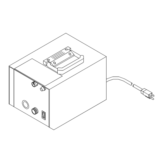
Page 26: Section 7 − Parts List
SECTION 7 − PARTS LIST Hardware is common and not available unless listed. 143328-K Figure 7-1. Complete Assembly Of WC-115A OM-1078 Page 22... - Page 27 Part Mkgs. Description Quantity Figure 7-1. Complete Assembly Of WC-115A ....276345 Handle, Rubberized Carrying ........
- Page 28 Notes OM-1078 Page 24...
- Page 29 Notes...
- Page 30 Notes Start Your Professional Over 80,000 trained 400 Trade Square East, Troy, Ohio 45373 Welding Career Now! since 1930! 1-800-332-9448 www.welding.org...
- Page 31 Effective January 1, 2022 (Equipment with a serial number preface of NC or newer) This limited warranty supersedes all previous Miller warranties and is exclusive with no other guarantees or warranties expressed or implied. LIMITED WARRANTY − Subject to the terms and conditions Supplied Air Respirator (SAR) Boxes and Panels below, Miller Electric Mfg.
- Page 32 Contact the Delivering Carrier to: File a claim for loss or damage during shipment. For assistance in filing or settling claims, contact your distributor and/or equipment manufacturer’s Transportation Department. © ORIGINAL INSTRUCTIONS − PRINTED IN USA 2022 Miller Electric Mfg. LLC 2022−01...
Need help?
Do you have a question about the WC-115A and is the answer not in the manual?
Questions and answers