
Related Manuals for Miller INTEGRA 135P


Summary of Contents for Miller INTEGRA 135P
- Page 1 OM-194 025 February 1999 Effective with serial number: 135P - 150925 175P - 150935 Processes MIG (GMAW) Welding Description INTEGRA 135P and 175P Visit our website at www.MillerWelds.com...
- Page 2 1929. This Owner’s Manual is designed to help you get the most out of your Miller products. Please take time to read the Safety precautions. They will help you protect yourself against potential hazards on the worksite. We’ve made installation and operation quick and easy.
-
Page 3: Table Of Contents
TABLE OF CONTENTS SECTION 1 – SAFETY PRECAUTIONS - READ BEFORE USING ..1-1. Symbol Usage ..........1-2. - Page 4 Via Privata Iseo, 6/E Indirizzo Costruttore: 20098 San Giuliano Milanese, Italy Declares that this product: INTEGRA 135P and 175P Dichiara che il Prodotto: Conforms to the following Directives and Standards: È Conforme alle seguenti Direttive e Norme. Direttive Electromagnetic Compatibility Directives: 89/336/EEC, 92/31/EEC Compatibilità...
-
Page 5: Section 1 - Safety Precautions - Read Before Using
SECTION 1 – SAFETY PRECAUTIONS - READ BEFORE USING som _nd_4/98 1-1. Symbol Usage Means Warning! Watch Out! There are possible hazards with this procedure! The possible hazards are shown in the adjoining symbols. This group of symbols means Warning! Watch Out! possible Y Marks a special safety message. - Page 6 ARC RAYS can burn eyes and skin. BUILDUP OF GAS can injure or kill. D Shut off shielding gas supply when not in use. Arc rays from the welding process produce intense D Always ventilate confined spaces or use visible and invisible (ultraviolet and infrared) rays that can burn eyes and skin.
-
Page 7: Additional Symbols For Installation, Operation, And Maintenance
1-3. Additional Symbols For Installation, Operation, And Maintenance FIRE OR EXPLOSION hazard. MOVING PARTS can cause injury. D Do not install or place unit on, over, or near D Keep away from moving parts such as fans. combustible surfaces. D Keep all doors, panels, covers, and guards D Do not install unit near flammables. -
Page 8: Emf Information
1-5. EMF Information Considerations About Welding And The Effects Of Low Frequency 1. Keep cables close together by twisting or taping them. Electric And Magnetic Fields 2. Arrange cables to one side and away from the operator. Welding current, as it flows through welding cables, will cause electro- magnetic fields. -
Page 9: Section 2 - Specifications
SECTION 2 – SPECIFICATIONS 2-1. Specifications Amperes Input at Rated Maximum Load Output, 50 or 60 Hz, Dimensions Weight Open- Model Rated Welding Output Single-Phase Range DC Range DC Circuit Circuit Rating Rating (mm) (mm) (Kg) (Kg) Voltage DC 230 V 130 A @ 20.5 Volts DC, 20% Duty Cycle 75 A @17.5 Volts DC,... -
Page 10: Section 3 - Installation
SECTION 3 – INSTALLATION 3-1. Installing Welding Gun Drive Assembly Gun Securing Thumbscrew Gun End Loosen thumbscrew. Insert gun end through opening until it bottoms against drive assembly. Tighten thumbscrew. Gun Trigger Leads Insert leads, one at a time, through small grommet on front panel. -
Page 11: Installing Gas Supply
3-4. Installing Gas Supply Obtain gas cylinder and chain to running gear, wall, or other station- Tools Needed: ary support so cylinder cannot fall and break off valve. 5/8, 1-1/8 in Cylinder Valve Remove cap, stand to side of valve, and open valve slightly. -
Page 12: Selecting A Location And Connecting Input Power
3-5. Selecting A Location And Connecting Input Power Rating Label Supply correct input power. Plug Obtain and install correct plug ac- Y Do not move or operate unit cording to its instructions. where it could tip. 18 in (457 mm) of Receptacle space for airflow Connect plug to matching recep-... -
Page 13: Electrical Service Guide For 230 Vac Model
3-6. Electrical Service Guide For 230 VAC Model Model 135P 175P Input Voltage Input Amperes At Rated Output 24.5 Max Recommended Standard Fuse Or Circuit Breaker Rating In Amperes Min Input Conductor Size In AWG/Kcmil Max Recommended Input Conductor Length In Meters Min Grounding Conductor Size In AWG/Kcmil Reference: 1996 National Electrical Code (NEC) S-0092-J... -
Page 14: Threading Welding Wire
3-8. Threading Welding Wire Wire Spool Welding Wire Inlet Wire Guide Pressure Adjustment Knob Drive Roll Outlet Wire Guide Gun Conduit Cable Lay gun cable out straight. Tools Needed: Hold wire tightly to keep it from unraveling. 4 in (102 mm) 6 in (150 mm) Open pressure assembly. -
Page 15: Section 4 - Operation
SECTION 4 – OPERATION 4-1. Controls Voltage Switch The higher the selected number, the thicker the material that can be welded. Do not switch under load. Wire Speed Control Use control to select a wire feed speed. As Voltage switch setting in- creases, wire speed range also in- creases. -
Page 16: Weld Parameters For 230 Vac Model
4-2. Weld Parameters For 230 VAC Model 205424A Welding Guide Settings are approximate. Adjust as required. WIRE THICKNESS WIRE GAS FLOW WELDING WIRE STICKOUT (Inches/ POLARITY VOLTAGE SPEED TO WELD: (Cubic Ft/Hr) TYPE\SIZE (Inches) Gauge) .022” HB–28 (.024) or C Auto Body DCEP 4.5–5.5... -
Page 17: Section 5 - Maintenance &Troubleshooting
SECTION 5 – MAINTENANCE &TROUBLESHOOTING 5-1. Routine Maintenance Y Disconnect power before maintaining. 3 Months Replace Repair or Clean unreadable replace tighten weld labels. cracked terminals. weld cable. 6 Months Blow out or vacuum inside. During heavy service, clean monthly. 5-2. -
Page 18: Replacing Gun Contact Tip
5-3. Replacing Gun Contact Tip Y Turn power before replacing contact tip. Nozzle Contact Tip Cut off welding wire at contact tip. Remove nozzle. Remove contact tip and install new contact tip. Reinstall nozzle. Tools Needed: Ref. ST-801 987 5-4. Troubleshooting Table Trouble Remedy No weld output;... -
Page 19: Section 6 - Electrical Diagrams
SECTION 6 – ELECTRICAL DIAGRAMS S2 MAX – – P.C.B. 230V 50/60Hz Figure 6-1. Circuit Diagram OM-194 025 Page 15... -
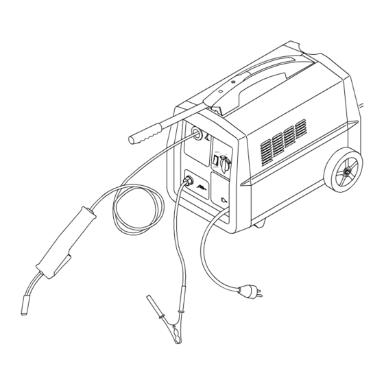
Page 20: Section 7 - Parts List
SECTION 7 – PARTS LIST Hardware is common and not available unless listed. Figure 7-1. Complete Assembly OM-194 025 Page 16... - Page 21 Qty. Qty. Item Ref. Code Item Ref. Code 156007029 VN.0.0.4 057098007 VP.0.4 056020053 VN.0.0.17 057098002 MU.0.3 P.C.B. 057084040 MU.0.1 156012092 VN.0.0.6 056126064 VP.0.1.1 056054062 VP.0.0.17 057021016 VN.0.2 156023159 ZH.0.0.11 057021017 VO.0.2 656110008 VN.0.12 156017152 VN.0.0.18 056050132 VP.0.0.23 156115002 VN.0.0.19 056159009 VP.0.0.21 156053047 MU.0.0.32 1 058021105 VN.1 756069028 VN.0.0.16...
- Page 23 Effective January 1, 1999 This limited warranty supersedes all previous Miller warranties and is exclusive with no other guarantees or warranties expressed or implied. LIMITED WARRANTY – Subject to the terms and conditions APT, ZIPCUT & PLAZCUT Model Plasma Cutting below, Miller Electric Mfg.
- Page 24 Phone: 414-735-4505 USA & Canada FAX: 920-735-4134 International FAX: 920-735-4125 European Headquarters – United Kingdom Phone: 44 (0) 1204-593493 FAX: 44 (0) 1204-598066 Miller Europe Italy Phone: 39 (0) 2982901 PRINTED IN USA 1999 Miller Electric Mfg. Co. 7/99...
Need help?
Do you have a question about the INTEGRA 135P and is the answer not in the manual?
Questions and answers