Table of Contents
Advertisement
Quick Links
OPERATION AND PARTS MANUAL
®
MODEL DCA25USI4CAN
60HZ WHISPERWATT™ GENERATOR
(ISUZU BV-4LE2-NYGD02 DIESEL ENGINE)
PARTS LIST NO. M1874400004
Revision #2 (11/23/16)
To find the latest revision of this
publication, visit our website at:
www.multiquip.com
THIS MANUAL MUST ACCOMPANY THE EQUIPMENT AT ALL TIMES.
Advertisement
Table of Contents

Related Manuals for MULTIQUIP WHISPERWATT DCA25USI4CAN


Summary of Contents for MULTIQUIP WHISPERWATT DCA25USI4CAN
- Page 1 OPERATION AND PARTS MANUAL ® MODEL DCA25USI4CAN 60HZ WHISPERWATT™ GENERATOR (ISUZU BV-4LE2-NYGD02 DIESEL ENGINE) PARTS LIST NO. M1874400004 Revision #2 (11/23/16) To find the latest revision of this publication, visit our website at: www.multiquip.com THIS MANUAL MUST ACCOMPANY THE EQUIPMENT AT ALL TIMES.
-
Page 2: Fuel And Chemical Exposure Warnings
FUEL AND CHEMICAL EXPOSURE WARNINGS Diesel engine exhaust and some of its constituents are know to cause cancer, birth defects and other reproductive harm. PAGE 2 — DCA25USI4CAN 60 HZ GENERATOR • OPERATION AND PARTS MANUAL — REV. #2 (11/23/16) -
Page 3: Reporting Safety Defects
If you believe that your vehicle has a defect that could cause a crash or could cause injury or death, you should immediately inform the National Highway Traffi c Safety Administration (NHTSA) in addition to notifying Multiquip Inc. at 1-800-421-1244. -
Page 4: Table Of Contents
TABLE OF CONTENTS COMPONENT DRAWINGS DCA25USI4CAN 60 Hz Generator Generator Assembly ......... 54-55 Control Box Assembly ........56-59 Fuel And Chemical Exposure Warnings ....2 Engine And Radiator Assembly ......60-63 Reporting Safety Defects ......... 3 Output Terminal Assembly ........ 64-65 Table Of Contents ............ -
Page 5: Parts Ordering Procedures
, 2006 Order via Internet (Dealers Only) Best Deal! If you have an MQ Account, to obtain a Username Order parts on-line using Multiquip’s SmartEquip website! and Password, E-mail us at: parts@multiquip. com. ■ View Parts Diagrams ■ Order Parts To obtain an MQ Account, contact your District Sales Manager for more information. -
Page 6: Safety Information
SAFETY INFORMATION Do not operate or service the equipment before reading the Potential hazards associated with the operation of this entire manual. Safety precautions should be followed at all equipment will be referenced with hazard symbols which times when operating this equipment. Failure to read and may appear throughout this manual in conjunction with understand the safety messages and operating instructions safety messages. - Page 7 SAFETY INFORMATION GENERAL SAFETY „ NEVER use accessories or attachments that are not recommended by MQ Power for this equipment. Damage CAUTION to the equipment and/or injury to user may result. „ NEVER operate this equipment without proper protective „ ALWAYS know the location of the nearest clothing, shatterproof glasses, respiratory protection, fi re extinguisher.
- Page 8 SAFETY INFORMATION ENGINE SAFETY NOTICE DANGER „ NEVER run engine without an air fi lter or with a dirty air fi lter. Severe engine damage may occur. Service air fi lter „ The engine fuel exhaust gases contain poisonous carbon frequently to prevent engine malfunction.
- Page 9 SAFETY INFORMATION FUEL SAFETY „ Make sure the hitch and coupling of the towing vehicle are rated equal to, or greater than the trailer “gross DANGER vehicle weight rating.” „ DO NOT start the engine near spilled fuel or combustible „...
- Page 10 SAFETY INFORMATION ELECTRICAL SAFETY „ Make sure power cables are securely connected to the generator’s output receptacles. Incorrect connections DANGER may cause electrical shock and damage to the generator. „ DO NOT touch output terminals during operation. Contact with output terminals NOTICE during operation can cause electrocution, „...
- Page 11 SAFETY INFORMATION EMISSIONS INFORMATION „ If the battery liquid (dilute sulfuric acid) comes into contact with clothing or skin, rinse skin or clothing NOTICE immediately with plenty of water. The diesel engine used in this equipment has been „ If the battery liquid (dilute sulfuric acid) comes into designed to reduce harmful levels of carbon monoxide contact with eyes, rinse eyes immediately with plenty (CO), hydrocarbons (HC) and nitrogen oxides (NOx)
-
Page 12: Specifications
SPECIFICATIONS Table 1. Generator Specifications Model DCA25USI4CAN Revolving field, self ventilated, Type drip-proof, single-bearing generator Armature Connection Star with Neutral Zigzag Phase Single Standby Output 27.5 kVA (22.0 KW) 15.8 KW Prime Output 25kVA (20 KW) 14.4 KW Power Factor Voltage 240 or 480V 240V/120V... -
Page 13: Dimensions
DIMENSIONS TOP VIEW SIDE VIEW FRONT VIEW Figure 1. Dimensions Table 3. Dimensions Reference Dimension in. (mm) Reference Letter Dimension in. (mm) Letter 22.64 in. (575 mm.) 70.47 in. (1,790 mm.) 20.87 in. (530 mm.) 49.61 in. (1,260 mm.) 27.36 in. (695 mm.) 31.1 in. -
Page 14: Installation
INSTALLATION GENERATOR GROUND LUG GROUND ROD FOR EARTH GROUND. CONNECT TO BUILDING GROUND CABLE GROUND IF APPLICABLE I N I T . / 2 REFERENCE NEC 250-83 (C) Figure 2. Typical Generator Grounding Application PAGE 14 — DCA25USI4CAN 60 HZ GENERATOR • OPERATION AND PARTS MANUAL — REV. #2 (11/23/16) - Page 15 INSTALLATION OUTDOOR INSTALLATION GENERATOR GROUNDING Install the generator in a area that is free of debris, To guard against electrical shock and possible damage to bystanders, and overhead obstructions. Make sure the the equipment, it is important to provide a good EARTH generator is on secure level ground so that it cannot slide ground.
-
Page 16: General Information
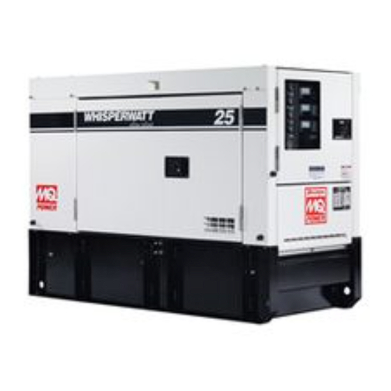
GENERAL INFORMATION GENERATOR OPEN DELTA EXCITATION SYSTEM This generator is equipped with the state of the art “Open- This MQ Power generator (Figure 3) is a high quality Delta” excitation system. The open delta system consist portable (requires a trailer for transport) power source for telecom sites, lighting facilities, power tools, submersible of an electrically independent winding wound among pumps and other industrial and construction machinery. -
Page 17: Major Components
MAJOR COMPONENTS 1000 2000 3000 R P M Table 4. Generator Major Components ITEM NO. DESCRIPTION Muffler Assembly Engine Assembly Enclosure Assembly Generator Assembly Output Terminal Assembly Battery Assembly Fuel Tank Assembly Generator Control Panel Assembly Engine Operating Panel Assembly Figure 3. -
Page 18: Generator Control Panel
GENERATOR CONTROL PANEL INCREASE DECREASE 1000 2000 STOP OPERATION (PRE-HEAT) 3000 START R P M Figure 4. Generator Control Panel The definitions below describe the controls and functions Located behind the generator control panel is the Generator of the Generator Control Panel (Figure 4). Control Box. -
Page 19: Engine Operating Panel
ENGINE OPERATING PANEL INCREASE DECREASE 1000 2000 STOP OPERATION (PRE-HEAT) 3000 START R P M Figure 5. Engine Operating Panel The definitions below describe the controls and functions 8. Ignition Switch — Three position switch, stop, operation and start. Insert ignition key to start and stop engine. of the Engine Operating Panel (Figure 5). -
Page 20: Output Terminal Panel Familiarization
OUTPUT TERMINAL PANEL FAMILIARIZATION OUTPUT TERMINAL PANEL OUTPUT TERMINAL FAMILIARIZATION The Output Terminal Panel (Figure 6) shown below is The “Output Terminal Panel ” (Figure 6) is provided with located on the right-hand side (left from control panel) of the following: the generator. - Page 21 OUTPUT TERMINAL PANEL FAMILIARIZATION 120 VAC GFCI Receptacles Each auxiliary receptacle is protected by a 50 amp circuit breaker. These breakers are located directly above the There are two 120 VAC, 20 amp GFCI (Duplex Nema GFCI receptacles. Remember the load output (current) on 5-20R) receptacles provided on the output terminal panel.
- Page 22 OUTPUT TERMINAL PANEL FAMILIARIZATION Connecting Loads Over Current Relay Loads can be connected to the generator by the output An over current relay (Figure 12) is connected to the main terminal lugs or the convenience receptacles (Figure 11). circuit breaker. In the event of an overload, both the circuit Make sure to read the operation manual before attempting breaker and the over current relay may trip.
-
Page 23: Load Application
LOAD APPLICATION SINGLE PHASE LOAD THREE PHASE LOAD Always be sure to check the nameplate on the generator When calculating the power requirements for 3-phase and equipment to insure the wattage, amperage, frequency, power use the following equation: and voltage requirements are satisfactorily supplied by the generator for operating the equipment. -
Page 24: Generator Outputs
GENERATOR OUTPUTS GENERATOR OUTPUT VOLTAGES Generator Amperage Table 8 shows the maximum amps the generator can A wide range of voltages are available to supply voltage for many different applications. Voltages are selected by using provide. DO NOT exceed the maximum amps as listed.. the voltage selector switch (Figure 13). -
Page 25: Generator Outputs/Gauge Reading
GENERATOR OUTPUTS/GAUGE READING HOW TO READ THE AC AMMETER AND AC AC Ammeter Gauge Reading VOLTAGE GAUGES Place the AC Ammeter Change-Over Switch (Figure 17) in the U position and observe the current reading (load The AC ammeter and AC voltmeter gauges are controlled drain) on the U terminal as indicated on the AC Ammeter by the AC ammeter and AC voltmeter change-over switches. -
Page 26: Output Terminal Panel Connections
OUTPUT TERMINAL PANEL CONNECTIONS UVWO TERMINAL OUTPUT VOLTAGES 3. Turn the voltage regulator knob (Figure 21) clockwise to increase voltage output, turn counterclockwise to Various output voltages can be obtained using the UVWO decrease voltage output. Use voltage regulator output terminal lugs. The voltages at the terminals are adjustment knob whenever fine tuning of the output dependent on the position of the Voltage Selector Switch voltage is required. - Page 27 OUTPUT TERMINAL PANEL CONNECTIONS 3Ø-480/277V UVWO Terminal Output Voltages 1Ø-240/120V UVWO Terminal Output Voltages 1. Place the voltage selector switch in the 3Ø 480/277 1. Place the voltage selector switch in the 1Ø 240/120 position as shown in Figure 24. position as shown in Figure 26.
-
Page 28: Vac Auto Transformer Connections
600 VAC AUTO TRANSFORMER CONNECTIONS 3Ø-600V Auto-Transformer 3. After drilling, make sure all shavings and debris have been removed from the enclosure. 3Ø, 600 VAC can be achieved via the auto-transformer 4. Install customer supplied conduit, fittings and bushing module. This module provides the necessary electronics through enclosure hole opening. -
Page 29: Inspection/Setup
INSPECTION/SETUP CIRCUIT BREAKERS FUEL CHECK To protect the generator from an overload, a 3-pole, 60 DANGER amp, main circuit breaker is provided to protect the U,V, Fuel spillage on a hot engine can cause and W Output Terminals from overload. In addition two a fire or explosion. - Page 30 INSPECTION/SETUP Refueling Procedure: 2. Open cabinet doors on the “right side” of the generator (from generator control panel position). Remove fuel WARNING cap and fill tank (Figure 34). Diesel fuel and its vapors are dangerous to your health and the surrounding environment.
- Page 31 INSPECTION/SETUP COOLANT (ANTIFREEZE/SUMMER COOLANT/ CLEANING THE RADIATOR WATER) The engine may overheat if the radiator fins become overloaded with dust or debris. Periodically clean the ISUZU recommends ISUZU antifreeze/summer coolant for radiator fins with compressed air. Cleaning inside the use in their engines, which can be purchased in concentrate machine is dangerous, so clean only with the engine turned (and mixed with 50% demineralized water) or pre-diluted.
- Page 32 INSPECTION/SETUP BATTERY When connecting battery do the following: 1. NEVER connect the battery cables to the battery This unit is of negative ground DO NOT connect in reverse. terminals when the ignition switch is in the START Always maintain battery fluid level between the specified position.
-
Page 33: Generator Start-Up Procedure
GENERATOR START-UP PROCEDURE BEFORE STARTING STARTING 1. Place the voltage selector switch in the desired CAUTION voltage position (Figure 41).. The engine’s exhaust contains harmful emissions. ALWAYS have adequate ventilation when operating. Direct exhaust away from nearby personnel. WARNING NEVER manually start the engine with the main, GFCI or auxiliary circuit breakers in the ON (closed) position. - Page 34 GENERATOR START-UP PROCEDURE 6. The generator’s AC-voltmeter (Figure 45) will display the generator’s output in VOLTS.. Figure 49. Coolant Temperature Gauge 11. The tachometer gauge (Figure 50) will indicate the speed of the engine when the generator is operating. Figure 45. Voltmeter Meter Under normal operating conditions this speed is approximately 1800 RPM’s.
-
Page 35: Generator Shut-Down Procedures
GENERATOR SHUT-DOWN PROCEDURES EMERGENCY SHUTDOWN PROCEDURE NORMAL SHUTDOWN PROCEDURE To shutdown the generator, use the following procedure: 1. Place the main, G.F.C.I., and aux. circuit breakers (Figure 55) in the OFF position. 1. Place both the MAIN, GFCI and LOAD circuit breakers as shown in Figure 53 to the OFF position. -
Page 36: Maintenance
MAINTENANCE 10 Hrs 1000 Table 14. Inspection/Maintenance 250 Hrs 500 Hrs DAILY Check Engine Fluid Levels Check Air Cleaner Check Battery Acid Level Check Fan Belt Condition Check for Leaks Check for Loosening of Parts Replace Engine Oil and Filter * Engine Clean Air Filter Check Fuel Filter/Water Separator Bowl... - Page 37 MAINTENANCE FUEL TANK INSPECTION If the engine is operating in very dusty or dry grass conditions, a clogged air cleaner will result. This can lead to In addition to cleaning the fuel tank, the following a loss of power, excessive carbon buildup in the combustion components should be inspected for wear: chamber and high fuel consumption.
- Page 38 MAINTENANCE CHECK OIL LEVEL RADIATOR CLEANING Check the crankcase oil level prior to each use, or when the The radiator (Figure 58) should be sprayed (cleaned) with fuel tank is filled. Insufficient oil may cause severe damage a high pressure washer when excessive amounts of dirt to the engine.
-
Page 39: Trailer Maintenance
TRAILER MAINTENANCE The following trailer maintenance guidelines are intended 6. Replace the adjusting-hole cover. to assist the operator in preventive maintenance. 7. Repeat the above procedure on all brakes. TRAILER BRAKES 8. Lower the trailer to the ground. Properly functioning brake shoes and drums are essential Check the fluid level in the master cylinder reservoir at least to ensure safety. - Page 40 TRAILER MAINTENANCE ADJUSTABLE WARNING CHANNEL Failure to maintain proper fluid level in the actuator 5/8" X 11" X 5" BOLT may result in loss of braking action which could cause severe property damage, injury or death. ADJUSTABLE CHANNEL 5/8" Periodically check the actuator mounting fasteners for NYLOC 2"...
- Page 41 TRAILER MAINTENANCE „ After removing the dust cap, cotter pin, spindle nut and DANGER spindle washer, remove the hub to inspect the bearings Improper weld repair will lead to early failure of the for wear and damage. trailer structure and can cause serious injury or death. „...
- Page 42 TRAILER MAINTENANCE Torque suspension components (Figure 63) as referenced Table 17. Tire Wear Troubleshooting in Table 16. Wear Pattern Cause Solution Table 16. Suspension Torque Requirements Adjust pressure to particular Center Wear Over inflation. load per tire manufacturer. Item Torque (Ft.-Lbs.) Adjust pressure to particular 3/8"...
- Page 43 TRAILER WIRING DIAGRAM Figure 64. Wheel Lug Nuts Tightening Sequenc NOTICE NEVER use an pneumatic air gun to tighten wheel lug nuts. DCA25USI4CAN 60 HZ GENERATOR • OPERATION AND PARTS MANUAL — REV. #2 (11/23/16) — PAGE 43...
-
Page 44: Trailer Wiring Diagram
TRAILER WIRING DIAGRAM Figure 65. Trailer/Towing Vehicle Wiring Diagram PAGE 44 — DCA25USI4CAN 60 HZ GENERATOR • OPERATION AND PARTS MANUAL — REV. #2 (11/23/16) -
Page 45: Generator Wiring Diagram
GENERATOR WIRING DIAGRAM Figure 66. Generator Wiring Diagram DCA25USI4CAN 60 HZ GENERATOR • OPERATION AND PARTS MANUAL — REV. #2 (11/23/16) — PAGE 45... -
Page 46: 600 Vac Auto Transformer Wiring Diagram
600 VAC AUTO TRANSFORMER WIRING DIAGRAM 3-POLE 30 AMPS CIRCUIT BREAKER DISJONCTEUR 30 AMPS À 3 PÔLES 6 AWG RED 6 AWG RED 6 AWG ROUGE 6 AWG ROUGE 6 AWG BLACK 6 AWG BLACK 6 AWG NOIR 6 AWG NOIR 6 AWG BLUE 6 AWG BLUE 6 AWG BLEU... - Page 47 NOTES DCA25USI4CAN 60 HZ GENERATOR • OPERATION AND PARTS MANUAL — REV. #2 (11/23/16) — PAGE 47...
-
Page 48: Engine Wiring Diagram
ENGINE WIRING DIAGRAM Figure 68. Engine Wiring Diagram PAGE 48 — DCA25USI4CAN 60 HZ GENERATOR • OPERATION AND PARTS MANUAL — REV. #2 (11/23/16) - Page 49 ENGINE WIRING DIAGRAM DCA25USI4CAN 60 HZ GENERATOR • OPERATION AND PARTS MANUAL — REV. #2 (11/23/16) — PAGE 49...
-
Page 50: Troubleshooting (Generator)
TROUBLESHOOTING (GENERATOR) Practically all breakdowns can be prevented by proper handling and maintenance inspections, but in the event of a breakdown, use Table 17 shown below for diagnosis of the Generator. If the problem cannot be remedied, consult our company’s business office or service plant. Table 19. - Page 51 NOTES DCA25USI4CAN 60 HZ GENERATOR • OPERATION AND PARTS MANUAL — REV. #2 (11/23/16) — PAGE 51...
-
Page 52: Explanation Of Code In Remarks Column
A blank entry generally indicates that the item is not sold assembly/kit that can be purchased, or is not available separately or is not sold by Multiquip. Other entries will for sale through Multiquip. be clarified in the “Remarks” Column. -
Page 53: Suggested Spare Parts
SUGGESTED SPARE PARTS DCA25USI4CAN WHISPERWATT GENERATOR WITH ISUZU BV-4LE2-NYGD02 DIESEL ENGINE 1 to 3 units Qty. Description 5....2944566410 ..ELEMENT, OIL FILTER 5....8980374810 ..ELEMENT, FUEL FILTER W/O SENSOR 3....8944370220 ..REPAIR KIT FUEL PUMP 3....0602046611 ..ELEMENT, AIR 1....8972309390 ..BELT, FAN 1....M1312500203 ..RADIATOR HOSE, UPPER 1....M1312500303 ..RADIATOR HOSE, LOWER 1....8970633010 ..SENSOR, WATER TEMP. -
Page 54: Generator Assembly
GENERATOR ASSY. PAGE 54 — DCA25USI4CAN 60 HZ GENERATOR • OPERATION AND PARTS MANUAL — REV. #2 (11/23/16) - Page 55 GENERATOR ASSY. PART NO. PART NAME QTY. REMARKS B1110200602 ROTOR ASSY ............1....INCLUDES ITEMS W/$ 1-1$ FIELD ASSY 1-2$ 7961025004 RECTIFIER 1-3$ 0601822630 SURGE ABSORBER 1-4$ 8001070003 1-5$ 8351611004 COUPLING DISK 1-6$ 8351612004 WASHER, COUPLING HUB 1-7$ B1112300003 BALANCING PLATE ..........1....ITEM 1-10 MUST BE ORDERED .....................WHEN REPLACING THE .....................BALANCING PLATE 1-8$...
-
Page 56: Control Box Assembly
CONTROL BOX ASSY. 32-1 PAGE 56 — DCA25USI4CAN 60 HZ GENERATOR • OPERATION AND PARTS MANUAL — REV. #2 (11/23/16) - Page 57 CONTROL BOX ASSY. PART NO. PART NAME QTY. REMARKS M1214000702 CONTROL BOX 0601807520 CIRCUIT BREAKER,60A T.C. 12V DC 0601827411 EF TERMINAL, KT1EF-3 0021005080 MACHINE SCREW 0601842384 RESISTOR 0027104010 MACHINE SCREW 0601823240 RECTIFIER 0027104030 MACHINE SCREW 0601815759 TERMINAL BOARD, 20 6P 0027104020 MACHINE SCREW 0601823863...
- Page 58 CONTROL BOX ASSY. (CONTINUED) 32-1 PAGE 58 — DCA25USI4CAN 60 HZ GENERATOR • OPERATION AND PARTS MANUAL — REV. #2 (11/23/16)
- Page 59 CONTROL BOX ASSY. (CONTINUED) PART NO. PART NAME QTY. REMARKS M1223000613 CONTROL PANEL 0601807641 FREQUENCY METER,240V 0601808985 AC METER. 0~50A/100A:5A1 0601801040 CHANGE-OVER SWITCH, AMMETER 0601806859 AC VOLTMETER, O~600V 0601801041 CHANGE-OVER SWITCH, VOLTMETER 0601840073 RHEOSTAT VR, 2W 1k OHM 0601840121 KNOB 0602103092 ALARM LAMP 0601810245...
-
Page 60: Engine And Radiator Assembly
ENGINE AND RADIATOR ASSY. PAGE 60 — DCA25USI4CAN 60 HZ GENERATOR • OPERATION AND PARTS MANUAL — REV. #2 (11/23/16) - Page 61 ENGINE AND RADIATOR ASSY. PART NO. PART NAME QTY. REMARKS M1924200094 ENGINE, ISUZU BV4LE2 8972309390 FAN BELT ............1....REPLACES P/N 0602011431 2944566410 ELEMENT, OIL FILTER ........1....REPLACES P/N 0602041210 .....................AND 8944567412 M1305200304 ENGINE FOOT M1305200204 ENGINE FOOT 0010310025 HEX HEAD BOLT 0040010000 WASHER, LOCK 0041210000 WASHER, FLAT...
- Page 62 ENGINE AND RADIATOR ASSY. (CONTINUED) PAGE 62 — DCA25USI4CAN 60 HZ GENERATOR • OPERATION AND PARTS MANUAL — REV. #2 (11/23/16)
- Page 63 ENGINE AND RADIATOR ASSY. (CONTINUED) PART NO. PART NAME QTY. REMARKS 0603300285 LOCKNUT 0605511395 VALVE 0603306395 HOSE JOINT 0602021070 0269200520 DRAIN HOSE M9602000003 DRAIN JOINT M9200200004 PLUG 0150000018 O-RING 0016906020 HEX HEAD BOLT 0199901600 DRAIN HOSE 0199900800 DRAIN HOSE 0605515106 HOSE BAND M9300000003 RESERVE TANK...
-
Page 64: Output Terminal Assembly
OUTPUT TERMINAL ASSY. ADD THE FOLLOWING DIGITS AFTER THE PART NUMBER WHEN ORDERING ANY PAINTED PANEL TO INDICATE COLOR OF UNIT. 1-ORANGE 2-WHITE 6-CATERPILLAR YELLOW 3-SPECTRUM GREY 7-CATO GOLD 4-SUNBELT GREEN 8-RED 5-BLACK 9-DESERT TAN THE SERIAL NUMBER MAY BE REQUIRED. PAGE 64 —... - Page 65 OUTPUT TERMINAL ASSY. PART NO. PART NAME QTY. REMARKS M1230700003 TERMINAL PANEL M9220000004 OUTPUT TERMINAL BOLT M9220000104 TIE BOLT 0039308000 HEX NUT 0040008000 WASHER, LOCK 0041408000 WASHER, FLAT 0016906025 HEX HEAD BOLT M1236101103 TERMANAL COVER M1238100704 OUTPUT WINDOW 0605010040 HINGE 0027103010 MACHINE SCREW 0030003000...
-
Page 66: Battery Assembly
BATTERY ASSY. PAGE 66 — DCA25USI4CAN 60 HZ GENERATOR • OPERATION AND PARTS MANUAL — REV. #2 (11/23/16) - Page 67 BATTERY ASSY. PART NO. PART NAME QTY. REMARKS 0602220185 BATTERY M9310500014 BATTERY SHEET M9103000304 BATTERY BAND 0602220920 BATTERY BOLT SET 0040006000 WASHER, LOCK M1348400204 BATTERY CABLE M1348400314 BATTERY CABLE 0016910020 HEX HEAD BOLT 0040510000 TOOTHED WASHER DCA25USI4CAN 60 HZ GENERATOR • OPERATION AND PARTS MANUAL — REV. #2 (11/23/16) — PAGE 67...
-
Page 68: Muffler Assembly
MUFFLER ASSY. PAGE 68 — DCA25USI4CAN 60 HZ GENERATOR • OPERATION AND PARTS MANUAL — REV. #2 (11/23/16) - Page 69 MUFFLER ASSY. PART NO. PART NAME QTY. REMARKS M1330000512 MUFFLER 0602302090 MUFFLER BLANKET M1333200304 GASKET 0016908035 HEX HEAD BOLT M1333300204 STAY 0016908020 HEX. HEAD BOLT M1333003013 EXHAUST PIPE 0605515146 HOSE BAND M1490003604 HEAT INSULATOR 8970420280 GASKET ............1....REPLACES P/N 0602320100 M1333200214 GASKET 0207008000 HEX NUT...
- Page 70 FUEL TANK ASSY. PAGE 70 — DCA25USI4CAN 60 HZ GENERATOR • OPERATION AND PARTS MANUAL — REV. #2 (11/23/16)
-
Page 71: Fuel Tank Assembly
FUEL TANK ASSY. PART NO. PART NAME QTY. REMARKS M1365000302 FUEL TANK 0605501071 FUEL SENDER UNIT 1-2A 0605516090 GASKET M1365200204 TANK BAND M1363200304 TANK BAND M9310500104 SUPPORTER SHEET 0016908020 HEX HEAD BOLT 0207008000 HEX NUT 0222100550 TANK SHEET 0191301200 VENT HOSE 0605515109 HOSE BAND 8943672922... -
Page 72: Enclosure Assembly
ENCLOSURE ASSY. ADD THE FOLLOWING DIGITS AFTER THE PART NUMBER WHEN ORDERING ANY PAINTED PANEL TO INDICATE COLOR OF UNIT. 1-ORANGE 2-WHITE 6-CATERPILLAR YELLOW 3-SPECTRUM GREY 7-CATO GOLD 4-SUNBELT GREEN 8-RED 5-BLACK 9-DESERT TAN THE SERIAL NUMBER MAY BE REQUIRED. PAGE 72 —... - Page 73 ENCLOSURE ASSY. PART NO. PART NAME QTY. REMARKS M1414000802 BASE M1493000504 ACOUSTIC SHEET M1415100202 ENVIROMENTAL TANK 0603306797 PLUG 0016910030 HEX HEAD BOLT M1413600004 DUCT 011008020 HEX HEAD BOLT ..........2....REPLACES P/N 0016908020 M1423002402 FRONT FRAME M1493108303 ACOUSTIC SHEET 0601850151 GROMMET M1423202602 FRONT DUCT M1493108003 ACOUSTIC SHEET...
- Page 74 ENCLOSURE ASSY. (CONTINUED) ADD THE FOLLOWING DIGITS AFTER THE PART NUMBER WHEN ORDERING ANY PAINTED PANEL TO INDICATE COLOR OF UNIT. 1-ORANGE 2-WHITE 6-CATERPILLAR YELLOW 3-SPECTRUM GREY 7-CATO GOLD 4-SUNBELT GREEN 8-RED 5-BLACK 9-DESERT TAN THE SERIAL NUMBER MAY BE REQUIRED. PAGE 74 —...
- Page 75 ENCLOSURE ASSY. (CONTINUED) PART NO. PART NAME QTY. REMARKS 0016906016 HEX HEAD BOLT 0207006000 HEX. NUT 0016908020 HEX HEAD BOLT M1444300403 REAR COVER M1493305104 ACOUSTIC SHEET M1443400103 DUCT M1493305204 ACOUSTIC SHEET 0207006000 HEX. NUT 0019208020 HEX HEAD BOLT M1444200303 REAR DOOR M1445600204 WINDOW PLATE 0207306000...
- Page 76 ENCLOSURE ASSY. (CONTINUED) ADD THE FOLLOWING DIGITS AFTER THE PART NUMBER WHEN ORDERING ANY PAINTED PANEL TO INDICATE COLOR OF UNIT. 1-ORANGE 2-WHITE 6-CATERPILLAR YELLOW 3-SPECTRUM GREY 7-CATO GOLD 4-SUNBELT GREEN 8-RED 5-BLACK 9-DESERT TAN THE SERIAL NUMBER MAY BE REQUIRED. PAGE 76 —...
- Page 77 ENCLOSURE ASSY. (CONTINUED) PART NO. PART NAME QTY. REMARKS M1453005003 SIDE DOOR M1493410004 ACOUSTIC SHEET M1455300403 DUCT M1495401204 ACOUSTIC SHEET M1495401404 ACOUSTIC SHEET 0207006000 HEX. NUT 0605012309 DOOR HANDLE ASSY. C9312500004 SEAL RUBBER 0176060030 HEX. NUT ............8....REPLACES P/N 0207006000 M9112100404 HINGE M9112100504 HINGE...
-
Page 78: Rubber Seals Assembly
RUBBER SEALS ASSY. PAGE 78 — DCA25USI4CAN 60 HZ GENERATOR • OPERATION AND PARTS MANUAL — REV. #2 (11/23/16) - Page 79 RUBBER SEALS ASSY. PART NO. PART NAME QTY. REMARKS 0229200790 SEAL RUBBER 0314500560 SEAL RUBBER 0229900630 SEAL RUBBER 0228901220 SEAL RUBBER 0228900690 SEAL RUBBER 0228800690 SEAL RUBBER 0228900340 SEAL RUBBER 0228900325 SEAL RUBBER 0229200325 SEAL RUBBER 0228800880 SEAL RUBBER 0228900375 SEAL RUBBER 0228900375 SEAL RUBBER...
-
Page 80: Nameplate And Decals Assembly
NAMEPLATE AND DECALS ASSY. D’AUTOCOLLANTS DECAL TRAILER PAGE 80 — DCA25USI4CAN 60 HZ GENERATOR • OPERATION AND PARTS MANUAL — REV. #2 (11/23/16) - Page 81 NAMEPLATE AND DECALS ASSY. PART NO. PART NAME QTY. REMARKS M1510300902 DECAL: OPERATING PROCEDURES ........1 ... M11030090 DECAL: OPERATING PROCEDURES (FRENCH) M1510301002 DECAL: GENERATOR CONTROL ........... 1 ... M11030100 M1550000104 DECAL: NOTE ................1 ... M15000010 EE57066 DECAL: NOTICE, 50AMP RECEPTACLES (ENGLISH) ... 1 ... EE57066 EE57067 DECAL: NOTICE, 50AMP RECEPTACLES (FRENCH) ...
- Page 82 NAMEPLATE AND DECALS ASSY. (CONTINUED) D’AUTOCOLLANTS DECAL TRAILER PAGE 82 — DCA25USI4CAN 60 HZ GENERATOR • OPERATION AND PARTS MANUAL — REV. #2 (11/23/16)
- Page 83 NAMEPLATE AND DECALS ASSY. (CONTINUED) PART NO. PART NAME QTY. REMARKS M9520200404 DECAL: OVER CURRENT RELAY ........... 1 ... M92020040 M1561000004 DECAL: MQ POWER ..............2 M1562100004 STRIPE ..................2 M1562100103 STRIPE: WHISPERWATT ............1 M1562100204 STRIPE: 25 ................1 M1562100304 STRIPE: 25 ................
-
Page 84: 600 Vac Transformer Assembly
3Ø 600 VAC TRANSFORMER ASSY. (OPTION) 030TL BACKSIDE OF DOOR PAGE 84 — DCA25USI4CAN 60 HZ GENERATOR • OPERATION AND PARTS MANUAL — REV. #2 (11/23/16) - Page 85 3Ø 600 VAC TRANSFORMER ASSY. (OPTION) PART NO. PART NAME QTY. REMARKS EE57537 STRAIGHT, LIQUID TIGHT FITTING EE5972 BUSHING, PLAST, 1-1/2" EE57531 KIT, NEUTRAL, BUS BAR EE57772 LABEL, VINYL, CB T1NQ030TL EE57530 ENCLOSURE, NEMA CIRCUIT BREAKER EE52421 CIRCUIT BREAKER T1NQ030TL EE58372 BUSHING, INSULATED WITH NUT EE57532...
-
Page 86: Terms And Conditions Of Sale - Parts
Multiquip be $5.00. meeting this requirement. liable for loss of profit or good will or for any Special order items. - Page 87 NOTES DCA25USI4CAN 60 HZ GENERATOR • OPERATION AND PARTS MANUAL — REV. #2 (11/23/16) — PAGE 87...
- Page 88 © COPYRIGHT 2016, MULTIQUIP INC. Multiquip Inc , the MQ logo and the MQ Power logo are registered trademarks of Multiquip Inc. and may not be used, reproduced, or altered without written permission. All other trademarks are the property of their respective owners and used with permission.
Need help?
Do you have a question about the WHISPERWATT DCA25USI4CAN and is the answer not in the manual?
Questions and answers