Table of Contents
Advertisement
Quick Links
PARTS AND OPERATION MANUAL
PARTS AND OPERATION MANUAL
DCA-25SSAI
WHISPERWATT
GENERATOR
MQ POWER
PARTS LIST NO. 3336000
Final Copy (06/30/01)
MULTIQUIP INC.
18910 WILMINGTON AVE.
CARSON, CALIFORNIA 90746 FAX: 800-672-7877
310-537-3700
800-421-1244
FAX: 310-537-3927
E-mail:mq@multiquip.com
TM
PARTS DEPARTMENT:
800-427-1244
SERVICE DEPARTMENT:
800-835-2551
FAX: 310-638-8046
•
www:multiquip.com
Advertisement
Table of Contents
Troubleshooting

Subscribe to Our Youtube Channel
Related Manuals for MULTIQUIP POWER WHISPERWATT DCA-25SSAI


Summary of Contents for MULTIQUIP POWER WHISPERWATT DCA-25SSAI
- Page 1 PARTS AND OPERATION MANUAL PARTS AND OPERATION MANUAL MQ POWER DCA-25SSAI WHISPERWATT GENERATOR PARTS LIST NO. 3336000 Final Copy (06/30/01) MULTIQUIP INC. PARTS DEPARTMENT: 18910 WILMINGTON AVE. 800-427-1244 CARSON, CALIFORNIA 90746 FAX: 800-672-7877 SERVICE DEPARTMENT: 310-537-3700 800-421-1244 800-835-2551 FAX: 310-537-3927 FAX: 310-638-8046 •...
- Page 2 PAGE 2 — DCA-25SSAI — PARTS AND OPERATION MANUAL—FINAL COPY (06/30/01)
-
Page 3: Here's How To Get Help
ARRANTY DEP ARRANTY DEP TMENT TMENT ARRANTY DEP ARRANTY DEPAR ARTMENT TMENT TMENT 800/835-2551 or 310/537-3700 FAX: 310/638-8046 MAIN MAIN MAIN MAIN MAIN 800/421-1244 or 310/537-3700 FAX: 310/537-3927 PAGE 3 — DCA-25SSAI — PARTS AND OPERATION MANUAL— FINAL COPY (06/29/01) -
Page 4: Table Of Contents
Output Terminal Assembly .........70-71 Battery Assembly ............72-73 Muffler Assembly ............74-75 Fuel Tank Assembly ..........76-77 Enclosure Assembly ..........78-81 Rubber Seal Assembly ..........82-83 Name Plate And Decals ..........84-85 PAGE 4 — DCA-25SSAI — PARTS AND OPERATION MANUAL—FINAL COPY (06/30/01) -
Page 5: Parts Ordering Procedures
10+ line items. Toll-free FAX: 800/6-PARTS-7 • 800-672-7877 *DISCOUNTS ARE SUBJECT TO CHANGE* Fax order discount and UPS special programs revised June 1, 1995 PAGE 5 — DCA-25SSAI — PARTS AND OPERATION MANUAL— FINAL COPY (06/29/01) -
Page 6: Rules For Safe Operation
An explosion or fire could result causing severe bodily harm or even death. Topping-off to filler por t is dangerous, as it tends to spill fuel. PAGE 6 — DCA-25SSAI — PARTS AND OPERATION MANUAL—FINAL COPY (06/30/01) - Page 7 Make sure power connecting cables are securely connected to the generator’s output terminals, insufficient tightening of the terminal connections may cause damage to the generator and electrical shock. PAGE 7 — DCA-25SSAI — PARTS AND OPERATION MANUAL— FINAL COPY (06/29/01)
- Page 8 I When loading the generator on a truck, be sure to use the front and back frame bars as a means to secure the generator during transport. PAGE 8 — DCA-25SSAI — PARTS AND OPERATION MANUAL—FINAL COPY (06/30/01)
- Page 9 , doctor doctor doctor and fire department doctor doctor fire department fire department fire department fire department . ground, down a drain or into any water source. PAGE 9 — DCA-25SSAI — PARTS AND OPERATION MANUAL— FINAL COPY (06/29/01)
-
Page 10: Towing And Transportation
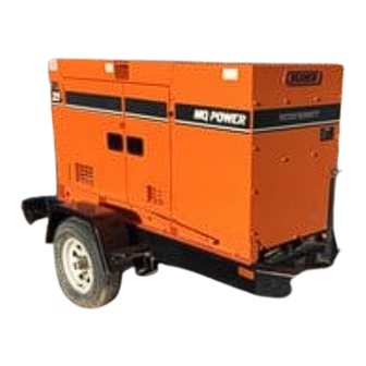
I DO NOT transport generator with fuel in tank. trailer. Also check the tire tread wear on both vehicles. I ALWAYS make sure the trailer is equipped with a "Safety Chain". Figure 1. Generator with Trailer PAGE 10 — DCA-25SSAI — PARTS AND OPERATION MANUAL—FINAL COPY (06/30/01) -
Page 11: Trailer Safety Guidelines
(empty). Frame Length - This measurement is from the ball hitch to the rear bumper (reflector). PAGE 11 — DCA-25SSAI — PARTS AND OPERATION MANUAL— FINAL COPY (06/29/01) - Page 12 " 6 " 6 " 7 " 4 " 4 " 2 " 3 " 8 " 3 " 8 " 3 " 4 " 6 " 4 " 6 PAGE 12 — DCA-25SSAI — PARTS AND OPERATION MANUAL—FINAL COPY (06/30/01)
- Page 13 " 7 7 - ) " 3 X " " 7 6 - ) " 3 X " " 7 X " " 7 X " " 7 PAGE 13 — DCA-25SSAI — PARTS AND OPERATION MANUAL— FINAL COPY (06/29/01)
- Page 14 CAUTION: Figure 2. Major Suspension Components NOTE ALWAYS wear safety glasses when removing or installing force fitted parts. Failure to comply may result in serious injury. PAGE 14 — DCA-25SSAI — PARTS AND OPERATION MANUAL—FINAL COPY (06/30/01)
- Page 15 " 2 " 3 " 4 Figure 3. Wheel Lug Nuts Tightening Sequence " 5 " 6 NOTE NEVER use an pneumatic air gun to tighten wheel lug nuts. PAGE 15 — DCA-25SSAI — PARTS AND OPERATION MANUAL— FINAL COPY (06/29/01)
-
Page 16: Trailer Wiring Diagram
DCA-25SSAI — TRAILER-WIRING DIAGRAM NOTE: LIGHTS ARE ORIENTED FROM THE DRIVER’S SEAT PAGE 16 — DCA-25SSAI — PARTS AND OPERATION MANUAL—FINAL COPY (06/30/01) -
Page 17: Operation Decals
DCA-25SSAI — GENERATOR DECALS The DCA-25SSAI generator is equipped with a number of safety decals. These decals are provided for operator safety and maintenance information. The illustration below and on the preceding pages show the decals as they appear on the machine. - Page 18 DCA-25SSAI — GENERATOR DECALS PAGE 18 — DCA-25SSAI — PARTS AND OPERATION MANUAL—FINAL COPY (06/30/01)
-
Page 19: Dca-25Ssai Specifications
. l a r h / i t p . l a r h / . l a r h / e t t l e s PAGE 19 — DCA-25SSAI — PARTS AND OPERATION MANUAL— FINAL COPY (06/29/01) -
Page 20: General Information
2 Load GFCI Circuit Breakers 120V@ 20amps creases frequency variation to ±.25%. Control Box The “Control Box” is provided with the following: Main Circuit Breaker 60 amps Over-Current Relay PAGE 20 — DCA-25SSAI — PARTS AND OPERATION MANUAL—FINAL COPY (06/30/01) -
Page 21: Major Components
DCA-25SSAI — MAJOR COMPONENTS Figure 4. Major Components PAGE 21 — DCA-25SSAI — PARTS AND OPERATION MANUAL— FINAL COPY (06/29/01) -
Page 22: Dimensions
DCA-25SSAI — DIMENSIONS (TOP, SIDE AND FRONT) Figure 5. Dimensions PAGE 22 — DCA-25SSAI — PARTS AND OPERATION MANUAL—FINAL COPY (06/30/01) - Page 23 NOTE PAGE PAGE 23 — DCA-25SSAI — PARTS AND OPERATION MANUAL— FINAL COPY (06/29/01)
- Page 24 DCA-25SSAI — CONTROL PANEL Figure 6. Control Panel PAGE 24 — DCA-25SSAI — PARTS AND OPERATION MANUAL—FINAL COPY (06/30/01)
-
Page 25: Control Panel Descriptions
Pilot Lamp- This will light if the oil pressure or water temperature is not within normal limits. If the lamp does not illuminate when the lamp switch is turned on, the bulb should be replaced. PAGE 25 — DCA-25SSAI — PARTS AND OPERATION MANUAL— FINAL COPY (06/29/01) -
Page 26: Engine Operating Panel Descriptions
DCA-25SSAI — ENGINE OPERATING PANEL Figure 7. Engine Operating Panel PAGE 26 — DCA-25SSAI — PARTS AND OPERATION MANUAL—FINAL COPY (06/30/01) - Page 27 Hz operation. This meter should indicate 1800 RPM’s when the rated load is applied. In addition a built in hour meter will record the number of operational hours that the generator has been in use. PAGE 27 — DCA-25SSAI — PARTS AND OPERATION MANUAL— FINAL COPY (06/29/01)
-
Page 28: Output Terminal Panel Descriptions
(see Figure 6, page 24). Place the voltmeter change-over switch to the U-W position and the ammeter change-over switch to the U or W to read the output. PAGE 28 — DCA-25SSAI — PARTS AND OPERATION MANUAL—FINAL COPY (06/30/01) - Page 29 DCA-25SSAI — OUTPUT TERMINAL PANEL NOTE Legs “O” and Ground are considered Bonded Grounds. Figure 10. Output Terminal Description PAGE 29 — DCA-25SSAI — PARTS AND OPERATION MANUAL— FINAL COPY (06/29/01)
-
Page 30: Output Amerage Setup
PAGE 30 — DCA-25SSAI — PARTS AND OPERATION MANUAL—FINAL COPY (06/30/01) - Page 31 14) to read the output on the selected leg. output terminal panel) NOTE When using plural single phase voltages, make sure to balance the load on each of the single phase legs. PAGE 31 — DCA-25SSAI — PARTS AND OPERATION MANUAL— FINAL COPY (06/29/01)
-
Page 32: Output Voltage Setup
(Figure 18). FIGURE 17. Voltage Selector Switch 480/277V Three Phase Position FIGURE 16. Hard Wire Hookup at 240/120V Position FIGURE 18. Hard Wire Hookup For 240V or 480V PAGE 32 — DCA-25SSAI — PARTS AND OPERATION MANUAL—FINAL COPY (06/30/01) - Page 33 Figure 20. Hard Wire Hookup for Three Phase 480V, 440V, or 416V Figure 22. Hard Wire Hookup for Single Phase 277V, 254V, or 240V PAGE 33 — DCA-25SSAI — PARTS AND OPERATION MANUAL— FINAL COPY (06/29/01)
- Page 34 Figure 26. Hard Wire Hookup for Single Phase 139V, 127V, Figure 24. Hard Wire Hookup for Three Phase 240V, 220V, or or 120V 208V PAGE 34 — DCA-25SSAI — PARTS AND OPERATION MANUAL—FINAL COPY (06/30/01)
- Page 35 After hooking up the hard wires to the lugs as shown in Figure 28, 240 volts can be obtained and using the voltage regulator to fine tune. Figure 28. Hard Wire Hookup for Single Phase 240 volt PAGE 35 — DCA-25SSAI — PARTS AND OPERATION MANUAL— FINAL COPY (06/29/01)
-
Page 36: Installation
NFPA 110, Chapter 5-4.1). DO NOT remove the metal skids on the bottom of the generator. They are to resist damage to the bottom of the generator and to maintain alignment. PAGE 36 — DCA-25SSAI — PARTS AND OPERATION MANUAL—FINAL COPY (06/30/01) - Page 37 DCA-25SSAI — INSTALLATION Figure 30. Typical Generator Grounding Application PAGE 37 — DCA-25SSAI — PARTS AND OPERATION MANUAL— FINAL COPY (06/29/01)
-
Page 38: Pre Setup
. t f . t f . t f . t f . t f . t f . t f t l u o r f t l o PAGE 38 — DCA-25SSAI — PARTS AND OPERATION MANUAL—FINAL COPY (06/30/01) - Page 39 Isuzu Engine Operator’s Manual. ° 4 ° 3 ° 0 ° 5 - ° 3 ° 5 ° 5 - ° 5 ° 5 1 - ( ) ° 5 PAGE 39 — DCA-25SSAI — PARTS AND OPERATION MANUAL— FINAL COPY (06/29/01)
- Page 40 Tighten the mounting bolt and the adjusting bolt. be less than 50%. be less than 50%. be less than 50%. be less than 50%. be less than 50%. PAGE 40 — DCA-25SSAI — PARTS AND OPERATION MANUAL—FINAL COPY (06/30/01)
- Page 41 Tighten all hose clamps and check hoses for leaks. If any hose (fuel or oil) lines are defective replace them Figure 33. Battery Connections immediately. PAGE 41 — DCA-25SSAI — PARTS AND OPERATION MANUAL— FINAL COPY (06/29/01)
-
Page 42: Load Application
Three Phase Load When calculating the power requirements for 3-phase power use the following equation: PAGE 42 — DCA-25SSAI — PARTS AND OPERATION MANUAL—FINAL COPY (06/30/01) -
Page 43: Generator Start-Up Procedure
G.F the “OFF” position prior to starting the engine. Figure 36. Battery Connections Figure 34. Main, GFCI and Load Circuit Breakers PAGE 43 — DCA-25SSAI — PARTS AND OPERATION MANUAL— FINAL COPY (06/29/01) - Page 44 (Figure 45) to increase or decrease the desired voltage. Figure 40. Ignition Switch ‘PREHEAT’ Figure 44. Voltage Meter (Volts) PAGE 44 — DCA-25SSAI — PARTS AND OPERATION MANUAL—FINAL COPY (06/30/01)
- Page 45 165 and 215 degrees Fahrenheit. Figure 51. Ammeter (Load) 18. The generator will run until manually stopped or an abnormal condition occurs. WATER TEMP Figure 48. Coolant Temperature Gauge PAGE 45 — DCA-25SSAI — PARTS AND OPERATION MANUAL— FINAL COPY (06/29/01)
-
Page 46: Generator Shutdown Procedure
3. Let the engine cool by running it for 3-5 minutes with no load applied. 4. Turn the ignition key to ‘STOP’ (Figure 53). Figure 53. Ignition Switch ‘STOP’ Remove the load from the UVW terminal strip. PAGE 46 — DCA-25SSAI — PARTS AND OPERATION MANUAL—FINAL COPY (06/30/01) - Page 47 NOTE PAGE PAGE 47 — DCA-25SSAI — PARTS AND OPERATION MANUAL— FINAL COPY (06/29/01)
-
Page 48: Maintenance
Securely fasten the fuel strainer cap so that fuel will not leak. Check the fuel strainer every 200 hours of operation or once a month. PAGE 48 — DCA-25SSAI — PARTS AND OPERATION MANUAL—FINAL COPY (06/30/01) -
Page 49: Generator Storage
. y l c a l e t l i s r i . y l PAGE 49 — DCA-25SSAI — PARTS AND OPERATION MANUAL— FINAL COPY (06/29/01) -
Page 50: Generator Wiring Diagram
DCA-25SSAI — GENERATOR WIRING DIAGRAM PAGE 50 — DCA-25SSAI — PARTS AND OPERATION MANUAL—FINAL COPY (06/30/01) -
Page 51: Engine Wiring Diagram
DCA-25SSAI — ENGINE WIRING DIAGRAM PAGE 51 — DCA-25SSAI — PARTS AND OPERATION MANUAL— FINAL COPY (06/29/01) -
Page 52: Engine Troubleshooting
. r a t s i n i l c a l e v i e v l . t s PAGE 52 — DCA-25SSAI — PARTS AND OPERATION MANUAL—FINAL COPY (06/30/01) - Page 53 . e l , t e g i t i l y , t l o i s e l z . r e PAGE 53 — DCA-25SSAI — PARTS AND OPERATION MANUAL— FINAL COPY (06/29/01)
-
Page 54: Generator/Engine Troubleshooting
PAGE 54 — DCA-25SSAI — PARTS AND OPERATION MANUAL—FINAL COPY (06/30/01) - Page 55 NOTE PAGE PAGE 55 — DCA-25SSAI — PARTS AND OPERATION MANUAL— FINAL COPY (06/29/01)
-
Page 56: Explanation Of Codes In Remarks Column
+, or %, belong to the same assembly or kit. Note: If more than one of the same reference number is listed, the last one listed indicates newest (or latest) part available. PAGE 56 — DCA-25SSAI — PARTS AND OPERATION MANUAL—FINAL COPY (06/30/01) -
Page 57: Suggested Spare Parts
2 ....5814200330 .... PREHEAT LAMP BULB NOTE Part number on this Suggested Spare Parts list may supercede/replace the P/N shown in the text pages of this book. PAGE 57 — DCA-25SSAI — PARTS AND OPERATION MANUAL— FINAL COPY (06/29/01) -
Page 58: Generator Assembly
DCA-25SSAI --- GENERATOR ASSY. GENERATOR ASSY. PAGE 58 — DCA-25SSAI — PARTS AND OPERATION MANUAL—FINAL COPY (06/30/01) - Page 59 7511342114 ARMATURE CORE 15-3 3331366013 ARMATURE COIL 0801350104 GROMMET 0601850264 GROMMET 7511315103 END BRACKET 7511350000 FIELD ASSY. EXCITER 19-1 7511352103 FIELD CORE, EXCITER 19-2 7511362103 FIELD COIL, EXCITER PAGE 59 — DCA-25SSAI — PARTS AND OPERATION MANUAL— FINAL COPY (06/29/01)
-
Page 60: Control Box Assembly
DCA-25SSAI --- GENERATOR ASSY. GENERATOR ASSY. PAGE 60 — DCA-25SSAI — PARTS AND OPERATION MANUAL—FINAL COPY (06/30/01) - Page 61 LOCK WASHER ........1 ... REPLACES 0040006000 0010006030 HEX. HEAD BOLT 0605000008 RUBBER SUSPENSION 031110160 PLAIN WASHER ........4 ... REPLACES 0041610000 0040010000 LOCK WASHER 020310080 HEX. NUT ..........4 ... REPLACES 0030110000 PAGE 61 — DCA-25SSAI — PARTS AND OPERATION MANUAL— FINAL COPY (06/29/01)
-
Page 62: Engine & Radiator Assembly
DCA-25SSAI --- CONTROL BOX ASSY. CONTROL BOX ASSY. PAGE 62 — DCA-25SSAI — PARTS AND OPERATION MANUAL—FINAL COPY (06/30/01) - Page 63 AC VOLTMETER ........1 ..PCK60 0~600V 0601801041 CHANGE-OVER SW., VOLTMETER ..1 ..SL2VS 0601810072 PILOT LAMP ..........1 ..LP132DC 220V 0601810261 BULB 0601840031 VOLTAGE REGULATOR ......1 ..RA30A2FE202BJ 0601840120 KNOB PAGE 63 — DCA-25SSAI — PARTS AND OPERATION MANUAL— FINAL COPY (06/29/01)
- Page 64 DCA-25SSAI --- CONTROL BOX ASSY. CONTROL BOX ASSY. PAGE 64 — DCA-25SSAI — PARTS AND OPERATION MANUAL—FINAL COPY (06/30/01)
- Page 65 HEX. NUT ..........4 ..REPLACES 0030008000 5825500422 EMERGENCY RELAY ....... 1 ..REPLACES 0602200406 AND 5825500191 9822531070 REGULATOR ..........1 ..REPLACES 0602201305 0027106016 MACHINE SCREW 0601830614 SWITCH CAP PAGE 65 — DCA-25SSAI — PARTS AND OPERATION MANUAL— FINAL COPY (06/29/01)
- Page 66 DCA-25SSAI ENGINE AND RADIATOR ASSY. ENGINE AND RADIATOR ASSY. PAGE 66 — DCA-25SSAI — PARTS AND OPERATION MANUAL—FINAL COPY (06/30/01)
-
Page 67: Engine Foot Assembly
CAP, RESERVE TANK 8012082103 BRACKET, RESERVE TANK ..1 ... REPLACES 3335182123 011606025 HEX. HEAD BOLT ......1 ... REPLACES 0017106025 0199500550 HOSE 0199500220 HOSE 0193600970 HOSE 0605515013 HOSE BAND PAGE 67 — DCA-25SSAI — PARTS AND OPERATION MANUAL— FINAL COPY (06/29/01) -
Page 68: Engine Operating Panel Assembly
DCA-25SSAI ENGINE AND RADIATOR ASSY. ENGINE AND RADIATOR ASSY. PAGE 68 — DCA-25SSAI — PARTS AND OPERATION MANUAL—FINAL COPY (06/30/01) - Page 69 PART NO. ITEM QTY. REMARKS 0194500600 BREATHER HOSE 0605515022 HOSE BAND 0193000500 HOSE 0605515005 HOSE BAND 0193100200 HOSE 0605515000 HOSE BAND 9829315110 EARTH CABLE ....... 1 ... REPLACES 0602220000 PAGE 69 — DCA-25SSAI — PARTS AND OPERATION MANUAL— FINAL COPY (06/29/01)
-
Page 70: Output Terminal Assembly
DCA-25SSAI --- ENGINE OPERATING PANEL ASSY. ENGINE OPERATING PANEL ASSY. PAGE 70 — DCA-25SSAI — PARTS AND OPERATION MANUAL—FINAL COPY (06/30/01) - Page 71 ENGINE STOPPER ......1 ... REPLACES 0602210802 3332159204 BRACKET, ENGINE STOPPER 0027106016 MACHINE SCREW 011008020 HEX. HEAD BOLT ......... 2 ... REPLACES 0017108020 3332152704 GOVERNOR ROD 0602180101 BALL JOINT PAGE 71 — DCA-25SSAI — PARTS AND OPERATION MANUAL— FINAL COPY (06/29/01)
-
Page 72: Battery Assembly
DCA-25SSAI --- ENGINE OPERATING PANEL ASSY. ENGINE OPERATING PANEL ASSY. PAGE 72 — DCA-25SSAI — PARTS AND OPERATION MANUAL—FINAL COPY (06/30/01) - Page 73 MACHINE SCREW ....... 4 ... S/N3312316~ 0040004000 LOCK WASHER ........4 ... S/N3312316~ 031104080 PLAIN WASHER ........8 ... S/N3312316~; REPLACES 0041204000 OEMAA8 HEX. NUT ..........4 ... S/N3312316~; REPLACES 0030104000 PAGE 73 — DCA-25SSAI — PARTS AND OPERATION MANUAL— FINAL COPY (06/29/01)
-
Page 74: Muffler Assembly
DCA-25SSAI --- BATTERY ASSY. BATTERY ASSY. PAGE 74 — DCA-25SSAI — PARTS AND OPERATION MANUAL—FINAL COPY (06/30/01) - Page 75 TERMINAL ASSY. (+) ....1 ... NO. 9N 0037808000 WING NUT ........1 ... REPLACES 0208008000 0602220311 TERMINAL ASSY. (-) ....1 ... NO. 9N 0037808000 WING NUT ........1 ... REPLACES 0208008000 PAGE 75 — DCA-25SSAI — PARTS AND OPERATION MANUAL— FINAL COPY (06/29/01)
-
Page 76: Fuel Tank Assembly
DCA-25SSAI --- MUFFLER ASSY. MUFFLER ASSY. PAGE 76 — DCA-25SSAI — PARTS AND OPERATION MANUAL—FINAL COPY (06/30/01) - Page 77 PLAIN WASHER ......4 ... REPLACES 0041608000 0040008000 LOCK WASHER 020108060 HEX. NUT ........4 ... REPLACES 0030008000 7342354004 COVER 011008020 HEX. HEAD BOLT ......4 ... REPLACES 0017108020 PAGE 77 — DCA-25SSAI — PARTS AND OPERATION MANUAL— FINAL COPY (06/29/01)
-
Page 78: Enclosure Assembly
DCA-25SSAI --- FUEL TANK ASSY. FUEL TANK ASSY. PAGE 78 — DCA-25SSAI — PARTS AND OPERATION MANUAL—FINAL COPY (06/30/01) - Page 79 SUCTION HOSE 0191300970 RETURN HOSE 0605515014 HOSE BAND 0845032204 DRAIN JOINT 0150000018 O RING .......... 1 ... REPLACES 0150000018 0802011104 PLUG 0193100255 FUEL GAUGE HOSE 0605515079 HOSE BAND PAGE 79 — DCA-25SSAI — PARTS AND OPERATION MANUAL— FINAL COPY (06/29/01)
- Page 80 DCA-25SSAI --- ENCLOSURE ASSY. ENCLOSURE ASSY. PAGE 80 — DCA-25SSAI — PARTS AND OPERATION MANUAL—FINAL COPY (06/30/01)
- Page 81 PLAIN WASHER ......... 6 .....REPLACES 0041606000 0040006000 LOCK WASHER 020106050 HEX. NUT ..........6 .....REPLACES 0030006000 0845028303 HINGE 011208025 HEX.HEAD BOLT ....... 4 .....REPLACES 0017108025 3335161902 ROOF PANEL PAGE 81 — DCA-25SSAI — PARTS AND OPERATION MANUAL— FINAL COPY (06/29/01)
-
Page 82: Rubber Seal Assembly
DCA-25SSAI --- ENCLOSURE ASSY. ENCLOSURE ASSY. PAGE 82 — DCA-25SSAI — PARTS AND OPERATION MANUAL—FINAL COPY (06/30/01) - Page 83 RUBBER SEAL 3335104304 RUBBER SEAL 3335104404 RUBBER SEAL 3335104504 RUBBER SEAL 3335104604 RUBBER SEAL 3335104704 RUBBER SEAL 3335104804 RUBBER SEAL 3335104904 RUBBER SEAL 3335103004 RUBBER SEAL 3335103104 RUBBER SEAL PAGE 83 — DCA-25SSAI — PARTS AND OPERATION MANUAL— FINAL COPY (06/29/01)
-
Page 84: Name Plate And Decals
DCA-25SSAI --- DECALS DECAL ASSY. PAGE 84 — DCA-25SSAI — PARTS AND OPERATION MANUAL—FINAL COPY (06/30/01) - Page 85 M9520200003 DECAL; CONNECTION OF OUTPUT CABLE ..1 ..M92020000 M9520200104 DECAL; OVER CURRENT RELAY ......1 ..M92020010 M1560100403 STRIPE;WHISPERWATT M1560100303 STRIPE;MQ POWER M1560100004 STRIPE; M1560100504 STRIPE; 25 M1560100104 STRIPE M1560100204 STRIPE PAGE 85 — DCA-25SSAI — PARTS AND OPERATION MANUAL— FINAL COPY (06/29/01)
-
Page 86: Cylinder Head And Cover Assembly
ISUZU C240 --- CYLINDER HEAD AND COVER ASSY. CYLINDER HEAD AND COVER ASSY. PAGE 86 — DCA-25SSAI — PARTS AND OPERATION MANUAL—FINAL COPY (06/30/01) - Page 87 CYLINDER HEAD COVER ASSY. 9117510381 OIL FILLER CAP 5111790520 BREATHER NIPPLE 5111730170 HEAD COVER PACKING 9111798080 HEAD COVER FIX. PACKING 9111791320 WAHER 5090000960 BOLT 5096050050 CYLINDER HEAD OIL COOLER PLUG PAGE 87 — DCA-25SSAI — PARTS AND OPERATION MANUAL— FINAL COPY (06/29/01)
-
Page 88: Cylinder Block Assembly
ISUZU C240 --- CYLINDER BLOCK ASSY. CYLINDER BLOCK ASSY. PAGE 88 — DCA-25SSAI — PARTS AND OPERATION MANUAL—FINAL COPY (06/30/01) - Page 89 REAR CYLINDER BLOCK PLATE 5090002270 BOLT 9112581080 OIL PAN BRIDGE CAP PACKING 5117490340 BREATHER HEAD PACKING 9019008180 BOLT 9019608180 BOLT 9092023080 PLUG; OIL GALLERY SCREW 9095714080 SCREW PLUG PACKING PAGE 89 — DCA-25SSAI — PARTS AND OPERATION MANUAL— FINAL COPY (06/29/01)
-
Page 90: Timing Gear Assembly
ISUZU C240 ---TIMING GEAR ASSY. TIMING GEAR ASSY. PAGE 90 — DCA-25SSAI — PARTS AND OPERATION MANUAL—FINAL COPY (06/30/01) - Page 91 PART NO. ITEM QTY. REMARKS 5113110282 TIMING GEAR CASE 9113211480 GEAR CASE COVER 9099206010 PACKING 901906140 BOLT 9113120460 PACKING 5096250790 OIL SEAL 9113270450 POINTER 9113120340 PACKING 9019108320 BOLT PAGE 91 — DCA-25SSAI — PARTS AND OPERATION MANUAL— FINAL COPY (06/29/01)
-
Page 92: Flywheel Housing Assembly
ISUZU C240 FLYWHEEL HOUSING ASSY. FLYWHEEL HOUSING ASSY. PAGE 92 — DCA-25SSAI — PARTS AND OPERATION MANUAL—FINAL COPY (06/30/01) - Page 93 FLYWHEEL HOUSING 9113430391 COVER 9019006120 BOLT 5113490380 STIFFENER; RIGHT SIDE 5113490370 STIFFENER; LEFT SIDE 9019110200 BOLT 23-1 9019110180 BOLT 9019310450 BOLT 9019110350 BOLT 9010560400 BOLT 9091104100 9091505100 LOCK WASHER PAGE 93 — DCA-25SSAI — PARTS AND OPERATION MANUAL— FINAL COPY (06/29/01)
-
Page 94: Oil Pan Assembly
ISUZU C240 OIL PAN ASSY. OIL PAN ASSY. PAGE 94 — DCA-25SSAI — PARTS AND OPERATION MANUAL—FINAL COPY (06/30/01) - Page 95 OIL LEVEL GAUGE 9019008220 BOLT 42-1 9019708450 BOLT 5117400870 OIL FILLER ASSY......1 ....INCL. ITEMS W/# 5117410100 OIL FILLER 5117500021 OIL FILLER CAP 9099207080 PACKING 9019008200 BOLT PAGE 95 — DCA-25SSAI — PARTS AND OPERATION MANUAL— FINAL COPY (06/29/01)
-
Page 96: Oil Pump Assembly
ISUZU C240 ---OIL PUMP ASSY. OIL PUMP ASSY. PAGE 96 — DCA-25SSAI — PARTS AND OPERATION MANUAL—FINAL COPY (06/30/01) - Page 97 PINION 9131130771 COVER 9020408250 BOLT 9091505080 LOCK WASHER 9091505080 LOCK WASHER 9131401200 OIL STRAINER ASSY......1 ... INCL. ITEM W/% 22*% 9131430100 OIL STRAINER GAUZE 9019708250 BOLT PAGE 97 — DCA-25SSAI — PARTS AND OPERATION MANUAL— FINAL COPY (06/29/01)
-
Page 98: Crankshaft, Bridge And Flywheel Assembly
ISUZU C240 --- CRANKSHAFT, BRIDGE AND FLYWHEEL ASSY. CRANKSHAFT, BRIDGE AND FLYWHEEL ASSY. PAGE 98 — DCA-25SSAI — PARTS AND OPERATION MANUAL—FINAL COPY (06/30/01) - Page 99 STRAIGHT PIN 5090001461 BOLT 5123360100 WASHER 9080307430 FEATHER KEY 9125210420 CRANKSHAFT GEAR ......1 ....Z=21 9123620390 THROWER 60-1 9123736051 CRANKSHAFT PULLEY 64-1 9098026060 BOLT 9123736060 THROWER 9123790160 WASHER PAGE 99 — DCA-25SSAI — PARTS AND OPERATION MANUAL— FINAL COPY (06/29/01)
-
Page 100: Oil And Fuel Filter Assembly
ISUZU C240 --- OIL AND FUEL FILTER ASSY. OIL AND FUEL FILTER ASSY. PAGE 100 — DCA-25SSAI — PARTS AND OPERATION MANUAL—FINAL COPY (06/30/01) - Page 101 OIL FILTER ASSY....... 1 ....INCL. ITEMS W/@ 111@ 8941564550 OIL FILTER CARTRIDGE 112@ 8941564540 OIL FILTER BODY 113@ 9132260090 ADAPTER 114@ 5131600030 RELIEF VALVE ASSY. 115@ 9099206200 PACKING ADAPTER PAGE 101 — DCA-25SSAI — PARTS AND OPERATION MANUAL— FINAL COPY (06/29/01)
-
Page 102: Oil Pipe Assembly
ISUZU C240 --- OIL PIPE ASSY. OIL PIPE ASSY. PAGE 102 — DCA-25SSAI — PARTS AND OPERATION MANUAL—FINAL COPY (06/30/01) - Page 103 PART NO. ITEM QTY. REMARKS 9133119810 OIL PUMP ASSY. 5133111141 ROCKER OIL FEED PIPE 9099061051 BOLT 9099209000 PACKING 5133111740 OIL INJECTION PIPE 5096750220 ADAPTER 9095720080 PACKING 901906120 BOLT PAGE 103 — DCA-25SSAI — PARTS AND OPERATION MANUAL— FINAL COPY (06/29/01)
-
Page 104: Water Pump And Fan Assembly
ISUZU C240 --- WATER PUMP AND FAN ASSY. WATER PUMP AND FAN ASSY. PAGE 104 — DCA-25SSAI — PARTS AND OPERATION MANUAL—FINAL COPY (06/30/01) - Page 105 5137700221 THERMOSTAT 5096050050 HEATER PLUG 5096370130 PACKING 9019708300 BOLT 9099168190 CLIP 9137168042 THERMOSTAT HOUSING 5137430050 HOUSING PACKING 9019708200 BOLT 9019108220 BOLT 9137211322 RUBBER BYPASS HOSE 9099156441 HOSE CLIP PAGE 105 — DCA-25SSAI — PARTS AND OPERATION MANUAL— FINAL COPY (06/29/01)
-
Page 106: Intake And Exhaust Manifold Assembly
ISUZU C240 --- INTAKE AND EXHAUST MANIFOLD ASSY. INTAKE AND EXHAUST MAINIFOLD ASSY. PAGE 106 — DCA-25SSAI — PARTS AND OPERATION MANUAL—FINAL COPY (06/30/01) - Page 107 GASKET 9091646080 PLAIN WASHER 9091505080 LOCK WASHER 9091104080 5090000870 BOLT 5143101961 INTAKE SHUTTER ASSY. 5096370150 THROTTLE VALVE PACKING 9091104080 9091505080 LOCK WASHER 5093600530 HOSE 5143340780 WIRE CONTROL BRACKET PAGE 107 — DCA-25SSAI — PARTS AND OPERATION MANUAL— FINAL COPY (06/29/01)
-
Page 108: Air Cleaner Assembly
ISUZU C240 --- AIR CLEANER ASSY. AIR CLEANER ASSY. PAGE 108 — DCA-25SSAI — PARTS AND OPERATION MANUAL—FINAL COPY (06/30/01) - Page 109 ELEMENT 5142110670 COVER 9142191410 INDICATOR 5142120560 DUST W/BAFFLE PAN 5142170040 CLAMP 9142170620 BOLT W/GASKET WASHER ..1 .... INCL. ITEMS W/# 9142191770 GASKET WASHER 9142176020 BAND ASSY. W/BOLT PAGE 109 — DCA-25SSAI — PARTS AND OPERATION MANUAL— FINAL COPY (06/29/01)
- Page 110 ISUZU C240 --- ENGINE FOOT ASSY. ENGINE FOOT ASSY. PAGE 110 — DCA-25SSAI — PARTS AND OPERATION MANUAL—FINAL COPY (06/30/01)
- Page 111 FRONT LIFTING HANGER 41-1 9117771360 REAR LIFTING HANGER 9141491730 REAR HANGER PIECE 9091105080 5197190060 ALTERNATOR FAN COVER 9091104080 9091505080 LOCK WASHER 5113190570 FRONT PLATE PACKING 8942059870 BOLT 52-1 9019108320 BOLT PAGE 111 — DCA-25SSAI — PARTS AND OPERATION MANUAL— FINAL COPY (06/29/01)
-
Page 112: Injection Pump Assembly
ISUZU C240 --- INJECTION PUMP ASSY. INJECTION PUMP ASSY. PAGE 112 — DCA-25SSAI — PARTS AND OPERATION MANUAL—FINAL COPY (06/30/01) - Page 113 INJECTION PUMP ASSY..... 1 ..... REPLACES 5156010252 INCL. ITEMS W/ 5157201400 GOVERNOR ASSY. 8941415340 FEED PUMP ASSY. 5157400720 AUTOMATIC TIMER 9197510790 INJ. PUMP SPACER BRACKET 9099205760 O RING PACKING 5125240660 INJ. PUMP GEAR PAGE 113 — DCA-25SSAI — PARTS AND OPERATION MANUAL— FINAL COPY (06/29/01)
-
Page 114: Electrical Parts Assembly
ISUZU C240 --- ELECTRICAL PARTS ELECTRICAL PARTS PAGE 114 — DCA-25SSAI — PARTS AND OPERATION MANUAL—FINAL COPY (06/30/01) - Page 115 GLOW PLUG 9825301090 CONTROL 9829513240 INSULATOR CAP 9829513250 INSULATOR CAP 9829513320 CABLE CAP 9197326100 CONNECTOR 5824500140 SWITCH 5825500190 EMERGENCY RELAY 1823100080 STARTER SWITCH 38-1 1823170070 9091114080 9091505080 LOCK WASHER PAGE 115 — DCA-25SSAI — PARTS AND OPERATION MANUAL— FINAL COPY (06/29/01)
-
Page 116: Accessories
ISUZU C240 --- ACCESSORIES ACCESSORIES PAGE 116 — DCA-25SSAI — PARTS AND OPERATION MANUAL—FINAL COPY (06/30/01) - Page 117 9193110240 CASE 9193110200 COVER 9193120060 PACKING 9193160270 GEAR 9193160170 GEAR 9019006160 BOLT 9090310100 NIPPLE 9099243550 OIL SEAL 9019008220 BOLT 9099211070 PACKING 5819000020 STOPPER ASSY. 91-1 5828480360 CABLE ASSY. PAGE 117 — DCA-25SSAI — PARTS AND OPERATION MANUAL— FINAL COPY (06/29/01)
-
Page 118: Injection Pump Comp. Assembly
ISUZU C240 ---INJECTION PUMP COMP. ASSY. INJECTION PUMP COMP. ASSY. PAGE 118 — DCA-25SSAI — PARTS AND OPERATION MANUAL—FINAL COPY (06/30/01) - Page 119 TAPPET SHIM ........A/R ..... T=1.05 55-18 9812350440 TAPPET SHIM ........A/R ..... T=1.15 55-19 9812350450 TAPPET SHIM ........A/R ..... T=1.25 55-20 5156190250 TAPPET SHIM ........A/R ..... T=0.25 PAGE 119 — DCA-25SSAI — PARTS AND OPERATION MANUAL— FINAL COPY (06/29/01)
- Page 120 ISUZU C240 --- INJECTION PUMP COMP. ASSY. INJECTION PUMP COMP. ASSY. PAGE 120 — DCA-25SSAI — PARTS AND OPERATION MANUAL—FINAL COPY (06/30/01)
- Page 121 5156290210 CAMSHAFT SHIM ......A/R ....... T=0.30 85-8 5156190390 CAMSHAFT SHIM ......A/R ....... T=0.70 85-9 1156190900 CAMSHAFT SHIM ......A/R ....... T=1.40 5156290050 HOUSING COVER 9019006140 BOLT PAGE 121 — DCA-25SSAI — PARTS AND OPERATION MANUAL— FINAL COPY (06/29/01)
-
Page 122: Governor Comp. Assembly
ISUZU C240 --- INJECTION PUMP COMP. ASSY. INJECTION PUMP COMP. ASSY. PAGE 122 — DCA-25SSAI — PARTS AND OPERATION MANUAL—FINAL COPY (06/30/01) - Page 123 ITEM QTY. REMARKS 9812214110 1156190820 BOLT 1157590010 PACKING 9097060370 BOLT 1096350070 PACKING 9812150780 TAPPET PLUG 9091606100 PLAIN WASHER 9091505100 LOCK WASHER 5156390020 9197510790 BRACKET 9099205760 O RING PACKING PAGE 123 — DCA-25SSAI — PARTS AND OPERATION MANUAL— FINAL COPY (06/29/01)
- Page 124 ISUZU C240 ---GOVERNOR COMP. ASSY. GOVERNOR COMP. ASSY. PAGE 124 — DCA-25SSAI — PARTS AND OPERATION MANUAL—FINAL COPY (06/30/01)
- Page 125 SHIM ..........A/R ..... T=1.00 9813222100 GOVERNOR SPRING 5157230820 LINK SPRING 1157230200 CAPSULE SPRING 9813932040 1156390080 GASKET 9813216360 CAPSULE SPRING 9008130230 9813217210 LEVER 9813250990 BUSHING 9813212050 O RING PACKING 9091854150 SNAP RING PAGE 125 — DCA-25SSAI — PARTS AND OPERATION MANUAL— FINAL COPY (06/29/01)
- Page 126 ISUZU C240 --- GOVERNOR COMP. ASSY. GOVERNOR COMP. ASSY. PAGE 126 — DCA-25SSAI — PARTS AND OPERATION MANUAL—FINAL COPY (06/30/01)
- Page 127 100* 9813217130 LINK 101* 1157290230 SNAP RING 102* 5157250170 TENSION LEVER 103* 9813250620 104* 5157250490 LEVER 116* 1157290010 GASKET 117* 1157290020 GASKET 148* 5157291120 BOLT 150* 5157230880 SPRING PAGE 127 — DCA-25SSAI — PARTS AND OPERATION MANUAL— FINAL COPY (06/29/01)
-
Page 128: Feed Pump Comp. Assembly
ISUZU C240 --- FEED PUMP COMP. ASSY. FEED PUMP COMP. ASSY. PAGE 128 — DCA-25SSAI — PARTS AND OPERATION MANUAL—FINAL COPY (06/30/01) - Page 129 9813516020 CHECK VALVE 1096230160 GASKET 9813517020 SPRING 9099063260 BOLT 1156190820 BOLT 1157590010 PACKING 1157590030 ADAPTER 1096230160 PACKING 9813550250 RING 9813521040 PUMP ..........1 ....... REPLACES 5157610050 9813550330 COVER PAGE 129 — DCA-25SSAI — PARTS AND OPERATION MANUAL— FINAL COPY (06/29/01)
-
Page 130: Auto Timer Assembly
ISUZU C240 --- AUTO TIMER COMP. ASSY. AUTO TIMER COMP. ASSY. PAGE 130 — DCA-25SSAI — PARTS AND OPERATION MANUAL—FINAL COPY (06/30/01) - Page 131 SHIM 12-6* 9813453300 SHIM 12-7* 9813453310 SHIM 12-8* 9813453320 SHIM 5157490070 WASHER 9813450520 PLATE 9813453060 5125240660 GEAR 20-1* 5156190480 LOCK WASHER 1156190010 5157490080 BOLT 9813433050 FLANGE 5157490280 HOLDER PAGE 131 — DCA-25SSAI — PARTS AND OPERATION MANUAL— FINAL COPY (06/29/01)
-
Page 132: Nozzle Holder Comp. Assembly
ISUZU C240 --- NOZZLE HOLDER COMP. ASSY. NOZZLE HOLDER COMP. ASSY. PAGE 132 — DCA-25SSAI — PARTS AND OPERATION MANUAL—FINAL COPY (06/30/01) - Page 133 PUSH ROD ......... 4 ....... INCL. ITEMS W/* 5153430020 SPRING 9153396010 SCREW 5153340030 9153390560 GASKET 9153390570 WASHER 9153326030 9153520050 GASKET 9153510070 CONNECTOR 5153490010 BOLT 9095714080 GASKET 9153596010 SCREW PAGE 133 — DCA-25SSAI — PARTS AND OPERATION MANUAL— FINAL COPY (06/29/01)
-
Page 134: Starter Comp. Assembly
ISUZU C240 ---STARTER COMP. ASSY. STARTER COMP. ASSY. PAGE 134 — DCA-25SSAI — PARTS AND OPERATION MANUAL—FINAL COPY (06/30/01) - Page 135 GEAR CASE ASSY........1 ....INCL. ITEM W/# 66*# 5811190260 FRONT METAL 5811290680 DUST COVER 5811270130 SHIFT LEVER ASSY. 5811510290 MAGNETIC SWITCH ASSY. 5811290710 BOLT 5811290730 WASHER PAGE 135 — DCA-25SSAI — PARTS AND OPERATION MANUAL— FINAL COPY (06/29/01)
-
Page 136: Alternator Comp. Assembly
ISUZU C240 --- ALTERNATOR COMP. ASSY. ALTERNATOR COMP. ASSY. (OCT. 1992~) PAGE 136 — DCA-25SSAI — PARTS AND OPERATION MANUAL—FINAL COPY (06/30/01) - Page 137 FRONT COVER ASSY........... 1 ..INCL. ITEMS W/& 18*& 5812290290 RETAINER 19*& 5098000870 BALL BEARING 22*& 5812291650 SCREW KIT 5812220760 PULLEY ASSY. 9822350150 5812291820 BOLT 5812291830 BOLT PAGE 137 — DCA-25SSAI — PARTS AND OPERATION MANUAL— FINAL COPY (06/29/01)
- Page 138 ISUZU C240 ---ALTERNATOR COMP. ASSY. ALTERNATOR COMP. ASSY. (BEFORE OCT. 1992) PAGE 138 — DCA-25SSAI — PARTS AND OPERATION MANUAL—FINAL COPY (06/30/01)
- Page 139 53*& 9822158240 RETAINER 54*& 9822159170 RETAINER BRIDGE 55*& 9000901820 FRONT BALL BEARING 5812220140 PULLEY ASSY. 9822350740 9822350720 BOLT ..............2 ..L=85 9822350730 BOLT ..............2 ..L=95 PAGE 139 — DCA-25SSAI — PARTS AND OPERATION MANUAL— FINAL COPY (06/29/01)
-
Page 140: Terms And Conditions Of Sales
RMA. products on the face hereof. A copy of the Return Material Authorization must accompany the return shipment. PAGE 140 — DCA-25SSAI — PARTS AND OPERATION MANUAL—FINAL COPY (06/30/01) - Page 141 NOTE PAGE PAGE 141 — DCA-25SSAI — PARTS AND OPERATION MANUAL— FINAL COPY (06/29/01)
- Page 142 TMENT TMENT 800/835-2551 or 310/537-3700 FAX: 310/638-8046 MAIN MAIN MAIN MAIN MAIN 800/421-1244 or 310/537-3700 FAX: 310/537-3927 MULTIQUIP INC. PARTS DEPARTMENT: 18910 WILMINGTON AVE. 800-427-1244 CARSON, CALIFORNIA 90746 FAX: 800-672-7877 SERVICE DEPARTMENT: 310-537-3700 800-421-1244 800-835-2551 FAX: 310-537-3927 FAX: 310-638-8046 •...
Need help?
Do you have a question about the POWER WHISPERWATT DCA-25SSAI and is the answer not in the manual?
Questions and answers