Table of Contents
Advertisement
Quick Links
BEGA
Installation and Technical Information
Tools Required:
• 5/16" concrete / masonry drill bit
• 4mm hex head screwdriver
• Hammer
• Adjustable wrench
Overview:
LED Watts:
11.6W
System Watts:
15.0W
Controllability:
0-10V dimmable
Weight:
34.8 lbs.
Protection Class: IP65
Notice to Installer:
1. See page 2 for specific product safety warnings.
2. Fixture may be damaged if connected to conduit systems that contain water - Article
300-5G of the National Electric Code requires that "Conduits or race ways through
which moisture may contact energized live parts shall be sealed or plugged at either
or both ends."
3. Bollard supplied with anchor kit 79825. Kit comes with (2) sleeve anchors for use in
pre-cast or finished concrete construction.
4. It is recommended that when installing in planting areas the bollard base be slightly
elevated to avoid prolonged submerging during heavy rains
5. Wet location does not imply suitability for exposure to standing water for long periods
06.17 · Technische Änderungen vorbehalten · Technical amendments reserved · Modifications techniques réservées
of time. Proper drainage must be provided.
!
79825 Anchor Kit Installation:
1. Provide conduit with supply wiring to bollard location in accordance with local code
The bollard base has a 3-1/4" opening to accommodate conduit.
2. Pour concrete and finish grade. Anchors do not need to be used during concrete
Erdstück
pour. Anchor kit comes with sleeve anchors for use after concrete installation is
complete.
Anchorage unit
3. Loosen (2) 4mm hex head set screws on the back of the bollard to remove bollard
base.
Pièce à enterrer
4. After establishing finished grade, mark the location of the (2) anchorage drill holes
using the mounting plate of the fixture as a template (Figure 1). Note the orientation
of the bollard base and the direction of light output.
5. Drill (2) 5/16" holes in concrete in the marked locations.
6. Align the bollard base with the drilled holes and drive the sleeve anchors through the
slots in the base into the holes until they are seated flush with the base.
7. Tighten the nut on top of the anchor to lock into place.
Optional 71890 Direct Burial Anchor Kit Installation:
1. Provide means to bring supply wiring to the conduit entry location in accordance with
local code.
2. Prepare soil for anchorage or cast the post in concrete.
3. Make sure anchorage is installed firmly into the ground and mounted level to the
surface.
4. NOTE: ENSURE THAT THE FLANGE PLATE IS ENTIRELY LEVEL AND FLUSH
WITH THE TOP EDGE OF THE SURFACE
5. Remove (2) mounting bolts and washers from the anchorage unit.
6. Align mounting base of the bollard tube, place onto top of anchorage post.
7. Secure by replacing (2) bolts through bollard base, into threaded holes of anchorage
flange. Tighten bolts firmly.
84415 Installation:
1. Make wiring connections between bollard and supply wiring inside bollard tube:
MAIN VOLTAGE SUPPLY WIRE TO BLACK DRIVER WIRE;
NEUTRAL (COMMON) SUPPLY WIRE TO WHITE DRIVER WIRE;
GREEN GROUND WIRE TO GREEN DRIVER WIRE.
0-10V Dimming (if applicable):
DIMMING CONTROL WIRE (+) TO POSITIVE DIM CONTROL WIRE
Gebrauchsanweisung
DIMMING CONTROL WIRE (-) TO NEGATIVE DIM CONTROL WIRE
2. Place bollard tube over bollard base and secure into place by tightening (2) 4mm
hex head screws.
Accessories
Anwendung
Please refer to the appropriate accessory installation
Erdstück für die Befestigung von
sheet for further instruction when applicable.
Pollerleuchten mit Fußplatte im Boden.
Produktbeschreibung
Erdstück besteht aus Stahl
Feuerverzinkt nach EN ISO 1461
2 Gewindeeinsätze mit Befestigungs-
Schrauben M8 x 25 aus Edelstahl
Werkstoff-Nr.: 1.4301
Abstand 220 mm
seitliche Leitungseinführung 70 x 30 mm
Gewicht: 2,2 kg
BEGA 1000 Bega Way, Carpinteria, CA 93013 (805)684-0533 © copyright BEGA 2021
Due to the dynamic nature of lighting products and the associated technologies, luminaire data on this sheet is subject to change at the discretion of BEGA North America. For the most current technical data, please refer to bega-us.com
Sicherheit
250
250
9 85
9 85
Instructions for use
Application
Anchorage unit for fixing bollards
with baseplate in the ground.
Product description
The anchorage unit is made of galvanised steel
according to EN ISO 1461
2 stainless steel thread inserts with stainless
steel mounting bolts M8 x 25
Grade-no. 1.4301
220 mm spacing
With lateral cable entry 70 x 30 mm
Weight: 2.2 kg
Safety indices
Dimensions
C
A
A: 10-1/2"
B: 39-3/8"
C: 4-3/4"
B
Figure 1:
NOTE: ANCHOR KIT DOES NOT INCLUDE TEMPLATE, USE BOLLARD BASE AS TEMPLATE (SHOWN)
Figure 2:
2 x M8
Flange Plate
Conduit Entry
Ø 75
Ø 75
220
220
Fiche d'utilisation
Utilisation
Pièce enterrée pour la fixation des balises
avec platine dans le sol.
Description du produit
La pièce enterrée est fabriquée en acier
galvanisé EN ISO 1461
2 filetages avec vis de fixation M8 x 25
en acier inoxydable
Matériau No.: 1.4301
Entraxe 220 mm
Entrée de câble latérale 70 x 30 mm
Poids: 2,2 kg
Sécurité
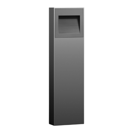
Bollard - shielded
REV
ANCHOR KIT INCLUDES (2)
5/16" X 2-1/2" STAINLESS
STEEL SLEEVE ANCHORS
71 890
3
3
"
4
1000 BEGA Way, Carpinteria, California 93013
8
5
"
APPROVED:
8
TYPE:
PROPRIETARY AND CONFIDENTIAL
THE INFORMATION CONTAINED IN THIS DRAWING IS THE SOLE PROPERTY
OF BEGA NORTH AMERICA, INC.
ANY REPRODUCTION IN PART OR AS A WHOLE WITHOUT THE WRITTEN
PERMISSION OF BEGA NORTH AMERICA, INC. IS PROHIBITED.
Maintenance:
Clean regularly with solvent-free cleaner
removing dirt and debris. Do not use high
pressure cleaners.
Replacement Parts
See label inside of fixture for LED replacement
part number.
Consult factory for all other replacement
components.
84 415
CHANGED BY
DESCRIPTION
DIRECTION OF
LIGHT OUTPUT
P (805) 684-0533
DATE:
DESCRIPTION:
ANCHOR KIT
SIZE
PART NO.
B
79825
NOT TO SCALE
5/24/202
Updated: 06/14/21
84 415
1 of 2
Advertisement
Table of Contents

Related Manuals for BEGA 84415


Summary of Contents for BEGA 84415
- Page 1 1 of 2 Due to the dynamic nature of lighting products and the associated technologies, luminaire data on this sheet is subject to change at the discretion of BEGA North America. For the most current technical data, please refer to bega-us.com...
- Page 2 2 of 2 Due to the dynamic nature of lighting products and the associated technologies, luminaire data on this sheet is subject to change at the discretion of BEGA North America. For the most current technical data, please refer to bega-us.com...
Need help?
Do you have a question about the 84415 and is the answer not in the manual?
Questions and answers