
Related Manuals for Rohde & Schwarz NRQ6


Summary of Contents for Rohde & Schwarz NRQ6
- Page 1 ® R&S NRQ6 Frequency Selective Power Sensor User Manual (;ÜTê2) 1178369202 Version 10...
- Page 2 ® This manual describes the R&S NRQ6 (1421.3509K02) with firmware version FW 02.40 and later. © 2023 Rohde & Schwarz GmbH & Co. KG Muehldorfstr. 15, 81671 Muenchen, Germany Phone: +49 89 41 29 - 0 Email: info@rohde-schwarz.com Internet: www.rohde-schwarz.com Subject to change –...
-
Page 3: Table Of Contents
Connecting to a power supply...................16 Connecting to a controlling host................17 3.6.1 Computer using a LAN connection................17 3.6.2 Computer using a USB connection................22 3.6.3 R&S NRX base unit.......................25 4 R&S NRQ6 tour..................27 RF connector....................... 27 Status information...................... 28 User Manual 1178.3692.02 ─ 10... - Page 4 ® Contents R&S NRQ6 LAN PoE+ interface.....................28 Host interface......................30 Trigger 2 I/O (TRIG2)....................30 Reference I/O (REF)....................30 Clock I/O (CLK)......................31 Local oscillator I/O (LO)....................31 Fan openings.......................31 5 Operating concepts................32 R&S NRP Toolkit......................32 5.1.1 Versions and downloads....................32 5.1.2...
- Page 5 ® Contents R&S NRQ6 7.2.2 Frequency adjustment for narrowband measurements..........51 Resolution bandwidth filters..................52 7.3.1 Filter characteristics...................... 52 7.3.2 Automatic filter type selection..................53 7.3.3 Choosing the correct filter type..................54 RF input attenuation....................56 Top pane parameters....................57 8 Measurement modes and result displays..........61 Continuous average mode..................
- Page 6 ® Contents R&S NRQ6 9.2.3 Dropout time........................89 9.2.4 Hold-off time........................90 9.2.5 Trigger jitter........................90 9.2.6 Trigger sender usage....................90 9.2.7 Trigger parameters......................91 Correction settings..................... 94 9.3.1 Corrections in the RF path.................... 94 9.3.2 Corrections in the IF path....................96 9.3.3 Correction parameters....................
- Page 7 ® Contents R&S NRQ6 12.6.1 Results of all kind......................130 12.6.2 Retrieving continuous average results................ 132 12.6.3 Retrieving trace results....................134 12.6.4 Retrieving ACLR results....................135 12.6.5 Retrieving IF spectrum results..................136 12.6.6 Retrieving I/Q trace results..................136 12.6.7 Configuring results...................... 136 12.7...
- Page 8 ® Contents R&S NRQ6 14.2.1 Overview........................196 14.2.2 Device status register....................198 14.2.3 Questionable status register..................199 14.2.4 Standard event status and enable register (ESR, ESE)..........201 14.2.5 Operation status register.....................202 15 Troubleshooting................. 207 15.1 Displaying status information..................207 15.2 Error messages......................207 15.2.1...
-
Page 9: Safety And Regulatory Information
Intended use The R&S NRQ6 is intended for precise and fast power measurements in development and for monitoring and maintenance purposes. The supported base units are listed in the data sheet. Observe the operating conditions and performance limits stated in the data sheet. -
Page 10: Labels On The Product
® Safety and regulatory information R&S NRQ6 Warning messages in the documentation Never open the casing of the product. Only service personnel authorized by Rohde & Schwarz are allowed to repair the product. If any part of the product is dam- aged or broken, stop using the product. -
Page 11: Welcome
Further documents are available at: www.rohde-schwarz.com/product/NRQ6 2.1.1 Getting started manual Introduces the R&S NRQ6 and describes how to set up and start working with the product. A printed version is delivered with the R&S NRQ6. 2.1.2 User manual Contains the description of all instrument modes and functions. It also provides an... -
Page 12: Application Sheets
Tutorials offer guided examples and demonstrations on operating the R&S NRQ6. They are provided on the product page of the internet. 2.1.6 Instrument security procedures Deals with security issues when working with the R&S NRQ6 in secure areas. It is available for download on the Internet. 2.1.7 Basic safety instructions Contains safety instructions, operating conditions and further important information. -
Page 13: Key Features
R&S NRQ6 Key features 2.2 Key features The R&S NRQ6 frequency selective power sensor sets standards in RF performance and usability. Outstanding key features are: ● Combines the advantages of a measurement receiver (dynamic range, linearity & video bandwidth) and a conventional diode-based or thermal power sensor (stabil- ity, absolute accuracy &... -
Page 14: Preparing For Use
® Preparing for use R&S NRQ6 Choosing the operating site 3 Preparing for use Here, you can find basic information about setting up the product for the first time. ● Unpacking and checking..................14 ● Choosing the operating site..................14 ●... -
Page 15: Considerations For Test Setup
● Minimum distance between the fan openings and any object is 10 cm. 3.4 Connecting to a DUT For connecting the R&S NRQ6 to a DUT, use the RF connector of the R&S NRQ6. See Chapter 4.1, "RF connector", on page 27. -
Page 16: Connecting To A Power Supply
1. NOTICE! Risk of damaging the center pin of the RF connector. Only rotate the hex nut of the RF connector. Never rotate the R&S NRQ6 itself. Carefully loosen the union nut at the front of the RF connector of the R&S NRQ6. 2. Remove the R&S NRQ6. -
Page 17: Connecting To A Controlling Host
R&S NRX base unit....................25 3.6.1 Computer using a LAN connection There are different ways to connect the R&S NRQ6 to a computer according to the available equipment. The power for the R&S NRQ6 is supplied over the LAN PoE+ interface. - Page 18 DUT", on page 15. 2. Connect the RJ.45 Ethernet connector of the R&S NRQ6 to an Ethernet switch that supports PoE+ power delivery. 3. Connect the computer to the Ethernet switch. 4. Establish a connection between the R&S NRQ6 and the network. See Chap- ter 3.6.1.4, "Establishing a...
- Page 19 DUT", on page 15. 2. Connect the RJ.45 Ethernet connector of the R&S NRQ6 to the output of the PoE+ injector. 3. Connect the PoE+ injector to a power supply. 4. Connect the input of the PoE+ injector to the non-PoE+ Ethernet switch.
- Page 20 DUT", on page 15. 2. Connect the RJ.45 Ethernet connector of the R&S NRQ6 to the output of the PoE+ injector. 3. Connect the PoE+ injector to a power supply. 4. Connect the computer to the input of the PoE+ injector.
- Page 21 ● <serial number> is the individual serial number of the R&S NRQ6. The serial number is printed on the bar code sticker at the rear side of the R&S NRQ6. It is the third part of the device ID: ID: 1421.3509K02 - 101441 - Zd...
-
Page 22: Computer Using A Usb Connection
3.6.2 Computer using a USB connection You can connect an R&S NRQ6 to a computer using the host interface and control it as described in Chapter 5, "Operating concepts",... - Page 23 5 = USB connector 6 = Computer with installed VISA driver or R&S NRP Toolkit 7 = PoE+ injector 8 = AC supply 1. Connect the R&S NRQ6 to the signal source (DUT). See Chapter 3.4, "Connecting to a DUT", on page 15.
- Page 24 3.6.2.2 R&S NRP‑Z5 sensor hub setup The R&S NRP‑Z5 sensor hub (high-speed USB 2.0) can host up to four R&S NRQ6 power sensors and provides simultaneous external triggering to all connected sensors. It comes with an external power supply unit, a power cable and a USB cable.
-
Page 25: R&S Nrx Base Unit
R&S NRP‑Z5 to the trigger device using a BNC cable. 3.6.3 R&S NRX base unit You can use an R&S NRX base unit as controlling host. Connect the R&S NRQ6 to the R&S NRX using the host interface. The R&S NRX supports the configuration of 2 directly connected R&S NRQ6, if enhanced accordingly. - Page 26 Insert this connector into one of the sensor ports of the R&S NRX. ► If you want to disconnect the cable from the host interface of the R&S NRQ6: a) Loosen the union nut of the screw-lock cable connector.
-
Page 27: S Nrq6 Tour
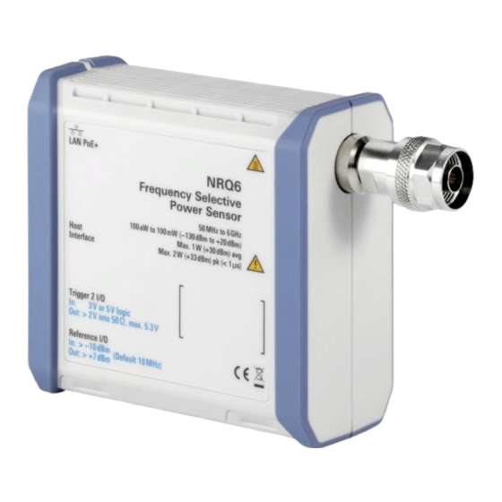
30 4.1 RF connector See (1) in Figure 4-1. The male N connector is used to connect the R&S NRQ6 to the device under test (DUT) or a signal generator, see Chapter 3.4, "Connecting to a DUT", on page 15. -
Page 28: Status Information
"To connect to the DUT" on page 15. 4.2 Status information See (2) in Figure 4-1. The status LED shows the state of the R&S NRQ6 by color and blinking frequency. Table 4-1: Possible states Color Illumination State White Steady... - Page 29 16. The power delivery at a USB host interface is not sufficient to run the R&S NRQ6 prop- erly. Therefore, you cannot use it as power supply for the R&S NRQ6. Figure 4-2: LAN [PoE+] interface...
-
Page 30: Host Interface
4.4 Host interface See (4) in Figure 4-1. The 8-pole male sensor connector (M12) is used to connect the R&S NRQ6 to a com- puter or an R&S NRX base unit. Further information: ● Chapter 3.6.1, "Computer using a LAN connection",... -
Page 31: Clock I/O (Clk)
4.9 Fan openings See (9, 10) in Figure 4-1. The R&S NRQ6 has fan openings on the top and on the bottom of the casing. When connecting the R&S NRQ6, be careful to allow sufficient airflow as specified in "Allow sufficient airflow"... -
Page 32: Operating Concepts
Chapter 5.4, "Remote control", on page 40 Also, the R&S NRQ6 is supported by the R&S Power Viewer. The R&S Power Viewer is provided on your documentation CD-ROM and on the Rohde & Schwarz website as a separate standalone installation package. -
Page 33: R&S Nrp Toolkit For Windows
® Operating concepts R&S NRQ6 R&S NRP Toolkit Supported Microsoft Windows versions: ● Microsoft Windows Vista 32/64-bit ● Microsoft Windows 7 32/64-bit ● Microsoft Windows 8/ 8.1 32/64-bit ● Microsoft Windows 10 32/64-bit 5.1.3 R&S NRP Toolkit for Windows The R&S NRP Toolkit installer for Windows-based systems contains the components described in the release notes available at www.rohde-schwarz.com/software/nrp-tool-... -
Page 34: Browser-Based User Interface
With the integrated, browser-based graphical user interface of the R&S NRQ6, you can easily configure the settings and measure in the provided measurement modes. Open a web browser on your controlling host and connect to the R&S NRQ6. No extra instal- lation is required. -
Page 35: Layout Of The Main Dialog
Chapter 3.4, "Connecting to a DUT", on page 15. To display the Web user interface 1. Open a supported web browser. 2. Enter the hostname of the R&S NRQ6 you want to connect to. See Chap- ter 3.6.1.5, "Using hostnames", on page 21. - Page 36 28. You can also display detailed information. Chapter 15.2, "Error messages", on page 207. If the R&S NRQ6 is in remote mode, the status is displayed next to the status LED, see Figure 5-2. Sensor information (3) in Figure 5-1 Serial number of the R&S NRQ6 and installed firmware version...
-
Page 37: Tooltips
® Operating concepts R&S NRQ6 Browser-based user interface Top pane (4) in Figure 5-1 Stays always visible. Chapter 7, "Adapting to the test signal", on page 49. Navigation pane (5) in Figure 5-1 For displaying measurement and system settings in the settings pane. -
Page 38: Setting Parameters
® Operating concepts R&S NRQ6 Browser-based user interface Table 5-1: Icons for chart analysis Icon Description Downloads the chart in PNG format. Zooms into the selected window. Moves the chart in the direction of both axes. Resets the axes. 5.2.4 Setting parameters If a parameter is not grayed, you can change its setting. -
Page 39: R&S Nrx
® Operating concepts R&S NRQ6 R&S NRX ► If you want to change a number, you can also: ● Use the spinner. One click changes the number by one increment. If you keep the arrow pressed, you can quickly scroll through the possible values. -
Page 40: Remote Control
The measurement starts, and the result is displayed in dBm. 5. If necessary, perform further settings. 5.4 Remote control You can remote control the R&S NRQ6 easily. The change to remote control occurs "on the fly". Switching to remote control 1. - Page 41 ® Operating concepts R&S NRQ6 Remote control The R&S NRQ6 changes into local mode. The lock of the web user interface is removed. Further information: ● Chapter 12, "Remote control commands", on page 118 ● Chapter 14, "Remote control basics", on page 193 ●...
-
Page 42: Measurement Basics
RBW > 40 MHz, the R&S NRQ6 works in zero-IF mode. 6.2 Measurement procedure in principle Unlike thermal or diode-based power sensors, the R&S NRQ6 is frequency selective. That means, you go about measuring differently than you are accustomed from the conventional power sensors. -
Page 43: Measurement Duration
98. 5. Start the measurement. To get measurement results quickly, the R&S NRQ6 offers numerous autoset features. In the web user interface, several settings are bundled together and controlled by an "Autoset" button. In remote control, each automatic setting is executed by a separate command. -
Page 44: Improving Measurement Results
R&S NRQ6 with a conventional 3-path-diode sensor that has a class leading dynamic range. Unlike the 3-path diode sensor, the R&S NRQ6 has no auto-averaging feature. Therefore, you have to define the measure- ment time manually when measuring with the R&S NRQ6. - Page 45 ® Measurement basics R&S NRQ6 Impact of measurement parameters on noise Figure 6-2: Measurement noise Figure 6-2 shows the resulting noise contribution for a fixed measurement time of 0.1 s, assuming that the filter settling time is far smaller than the integration time and that the noise floor power is much smaller than the power level.
-
Page 46: Potential Sources Of Error
6.6.1 Spurious response frequencies The hardware design of the R&S NRQ6 differs fundamentally from a spectrum ana- lyzer. Therefore, the R&S NRQ6 cannot provide a similar level of spurious response rejection. For isolated signals with small bandwidths and correctly specified measure- ment frequencies, that is no problem. -
Page 47: Lo Leakage
Potential sources of error -100 Frequency / GHz Figure 6-4: Typical spurious response of R&S NRQ6 set at 1 GHz input frequency, 20 MHz resolution bandwidth and right sideband 1 = 1st harmonic (right sideband: 1 GHz) 2 = 3rd harmonic (left sideband: 2.900 GHz) 3 = 5th harmonic (right sideband: 4.900 GHz) - Page 48 ® Measurement basics R&S NRQ6 Potential sources of error is a signal generator with level control, the LO leakage of the R&S NRQ6 can lead to a wrong level setting. Example: LO frequency and harmonics Settings: ● Carrier frequency of the applied signal: 800 MHz ([SENSe<Sensor>:]FREQuency[:CENTer])
-
Page 49: Adapting To The Test Signal
Automatic settings 7 Adapting to the test signal The R&S NRQ6 is a frequency selective power sensor. Before starting a measure- ment, you need to take the test signal and its properties into account. You can do that either automatically by using the autoset function, or by setting the fre- quency, filter, bandwidth and attenuation manually. -
Page 50: Frequency Configuration
The center frequency defines the mixing frequency in the downconversion process. Signals outside of the analysis bandwidth are filtered out. However, the R&S NRQ6 is sensitive to signals at frequencies related to the harmonics of the conversion fre- quency. -
Page 51: Frequency Adjustment For Narrowband Measurements
You can synchronize the reference frequencies of the R&S NRQ6 and the signal source. Make sure that center frequency is specified accurately. Use the REF connector of the R&S NRQ6 to lock the R&S NRQ6 to the reference fre- quency of the signal source or vice versa. -
Page 52: Resolution Bandwidth Filters
-120 dBm mum bandwidth 7.3 Resolution bandwidth filters The R&S NRQ6 supports different filter types. Each filter type is optimized for a differ- ent goal. Thus, it is possible to adapt the R&S NRQ6 to various measurement situa- tions. 7.3.1 Filter characteristics... -
Page 53: Automatic Filter Type Selection
7-4. 7.3.2 Automatic filter type selection In many situations, it is appropriate to let the R&S NRQ6 automatically choose the filter type for the measurement. The selection process is based on the currently selected measurement mode and, for some modes, also on the resolution bandwidth. -
Page 54: Choosing The Correct Filter Type
If you choose a filter with a high output sample rate, the resulting amount of data can become too huge for the R&S NRQ6 to process. The R&S NRQ6 indicates this condition by a static error due to insufficient memory. - Page 55 ® Adapting to the test signal R&S NRQ6 Resolution bandwidth filters Filter type Entered Pass BW 3 dB BW Stop BW Output Rise time Filter set- Equivalent sample rate tling time noise BW 5.4 μs 433.7 μs Flat 100 kHz 100.0 kHz...
-
Page 56: Rf Input Attenuation
® Adapting to the test signal R&S NRQ6 RF input attenuation Filter type Entered Pass BW 3 dB BW Stop BW Output Rise time Filter set- Equivalent sample rate tling time noise BW 560.4 μs Normal 1 kHz 1.0 kHz 5.1 kHz... -
Page 57: Top Pane Parameters
® Adapting to the test signal R&S NRQ6 Top pane parameters 2. Increase the average count until the measurement results are stable. 7.5 Top pane parameters Access: main dialog of the web user interface > top pane In the web user interface, these settings are grouped in the top pane. -
Page 58: Frequency
® Adapting to the test signal R&S NRQ6 Top pane parameters Within the chart, the cursor becomes a crosshair. The x-position (frequency) of the crosshair is shown on black background below the x-axis, the y-position (power) is shown in the color of the graph. -
Page 59: State
® Adapting to the test signal R&S NRQ6 Top pane parameters <State> ← Filter / Bandwidth Enables or disables the automatic filter type selection. "Manual" Select the filter under "<Filter type>" on page 59. "Auto" The selection depends on the currently chosen measurement mode and bandwidth. -
Page 60: Level
® Adapting to the test signal R&S NRQ6 Top pane parameters <Level> ← Attenuator Only available if "Manual" is set under <State>. Sets the input attenuation. Remote command: [SENSe<Sensor>:]INPut:ATTenuation S-Parameter For background information, see Chapter 12.9.7.4, "S-parameter corrections", on page 163. -
Page 61: Measurement Modes And Result Displays
Measuring modulated signals................. 63 ● Continuous average parameters................63 ● Continuous average result display................65 8.1.1 Averaging domains In continuous average and trace mode, the R&S NRQ6 supports three different aver- aging domains with the following characteristics. User Manual 1178.3692.02 ─ 10... - Page 62 ® Measurement modes and result displays R&S NRQ6 Continuous average mode Table 8-1: Averaging domains Power averaging Logarithmic aver- Amplitude averag- aging Command option "Power" "Video" "Linear" Averaging unit Watt Measurement bias caused by noise High Medium floor Measurement uncertainty caused...
-
Page 63: Measuring Modulated Signals
® Measurement modes and result displays R&S NRQ6 Continuous average mode Signal type "Averaging Domain" Explanation Continuous wave (CW) "Video" No noticeable measurement bias for a signal-to- noise ratio equal to and above 8 dB. Increase in measurement uncertainty is negligible. - Page 64 ® Measurement modes and result displays R&S NRQ6 Continuous average mode Moving Average......................65 Aperture Time........................65 Duty Cycle........................65 Autoset Starts a continuous measurement. Remote command: TRIGger:SOURce IMMediate INITiate:CONTinuous Trigger Mode "Trigger Mode" on page 91. Trigger Level "Trigger Level" on page 92.
-
Page 65: Continuous Average Result Display
Sets the duty cycle for measuring pulse-modulated signals. The duty cycle defines the percentage of one period during which the signal is active. If the duty cycle is enabled, the R&S NRQ6 considers this percentage when calculating the signal pulse power from the average power. -
Page 66: Trace Mode
CALCulate:FEED 8.2 Trace mode In this mode, the R&S NRQ6 measures power over time. The number of measurement points and the measurement time is defined. The length of an individual measurement is determined from the ratio of total time and the defined number of measurement points. - Page 67 ® Measurement modes and result displays R&S NRQ6 Trace mode Averaging Domain......................67 Moving Averaging......................68 Additional Traces......................68 Autoset Adjusts the following: ● Adjusts the trace settings to the current signal. ● Optimizes the scaling of the x- and y-axes. ● Sets the trigger to ensure a stable presentation of the test signals.
-
Page 68: Trace Result Display
® Measurement modes and result displays R&S NRQ6 Trace mode Moving Averaging "Moving Average" on page 65. Remote command: [SENSe<Sensor>:]TRACe:AVERage:TCONtrol Additional Traces Enables or disables the display of additional traces. The additional traces show the measurement results of the auxiliary measurands, peak and random. - Page 69 ® Measurement modes and result displays R&S NRQ6 Trace mode To move the plot Use the mouse to move the plot in x- and y-direction. 1. Place the mouse over the x-axis. 2. With the left mouse button pressed, drag the x-axis to the right or left.
-
Page 70: Aclr Mode
® Measurement modes and result displays R&S NRQ6 ACLR mode Measurement sequence ● "Peak": Peak value of the samples per trace point, available in trace mode if the number of measured values is sufficient. See "Requirements in trace mode" on page 130. -
Page 71: Aclr Result Display
® Measurement modes and result displays R&S NRQ6 ACLR mode Trigger Source.......................71 Trigger Delay.........................71 Aperture Time........................71 Autoset Starts a continuous measurement. Remote command: TRIGger:SOURce IMMediate INITiate:CONTinuous Trigger Mode "Trigger Mode" on page 91. Trigger Level "Trigger Level" on page 92. -
Page 72: Dc Zeroing In Aclr Mode
If you use the LTE filter with 10 MHz, 15 MHz or 20 MHz resolution bandwidth, a DC offset can occur. For example with 20 MHz ACLR bandwidth, the R&S NRQ6 meas- ures internally with a total bandwidth of 100 MHz. If you measure signals of low power, the TX channel shows a DC offset. -
Page 73: If Spectrum Preview
(R&S VSE) from Rohde & Schwarz. An application sheet describes the use of the R&S NRQ6 as an I/Q data source for the software R&S VSE vector signal explorer. It has the title "VSE Feed (I/Q Capturing)" and is available at: www.rohde-schwarz.com/manual/NRQ6... -
Page 74: Phase Coherent Measurements
Chapter 10.1, "Option management", on page 107. Using two R&S NRQ6, you can measure phase coherence in a multitone analysis. By measuring the relative phase error between calibration port and each antenna port, you can calibrate active antenna modules for beamforming. - Page 75 Figure 4-1. Configuration for calibration 1. Enable the use of an external reference clock for the R&S NRQ6, to which the external reference is fed. 2. Establish a sender/receiver relationship for triggering: a) Configure the R&S NRQ6 that is fed the external reference as sender.
- Page 76 Setup for measurement Figure 8-3: Measuring the phase difference 1 = 2-port DUT (signal source) 2 = External reference fed into the reference clock of the sender R&S NRQ6. 3 = RF connector 4 = R&S NRQ6 5 = Sampling clock connection...
-
Page 77: Setting The Sample Rate
8.5.3 I/Q trace parameters Requires the I/Q data interface (R&S NRQ6-K1). If a parameter requires an additional option, the option is listed in the parameter description. Access: main dialog of the web user interface > navigation pane > "I/Q"... -
Page 78: Autoset
® Measurement modes and result displays R&S NRQ6 I/Q trace mode Autoset.......................... 78 Trigger Mode......................... 78 Trigger Level......................... 78 Trigger Source.......................78 Trigger Delay.........................78 Result Length........................ 78 Specify Bandwidth by....................79 Variable Bandwidth......................79 Desired Sample Rate....................79 Used Sample Rate......................79 Sync Mode........................ -
Page 79: Specify Bandwidth By
● RBW ≤ 5 MHz with normal filter type ● Sample rate ≤ 40 MHz If an exact value is set that is out of range, the R&S NRQ6 indicates a static error. See also Chapter 4.2, "Status information", on page 28. -
Page 80: Power Servoing
This procedure can take several 10 ms, which is a long time for automated test applications. A R&S NRQ6 fitted with the power servoing option, combined with an R&S SGT100A signal generator, offers a much faster solution. The R&S NRQ6 measures continuously and sends the results to the signal generator, using a serial interface. - Page 81 1. Connect the instruments as shown in Figure 8-4. 2. Make sure to connect the TRIG2 connector of theR&S NRQ6 to the USER 2 con- nector of the R&S SGT100A. 3. Connect all instruments and the computer to the local network.
-
Page 82: Measurement Configuration
88 9.1.1 Controlling the measurement results The R&S NRQ6 can cope with the wide range of measurement scenarios with the help of the so-called "termination control". Depending on how fast your measurement results change, you can define, how the measurement results are output. -
Page 83: Interplay Of The Controlling Mechanisms
® Measurement configuration R&S NRQ6 Controlling the measurement Repeating termination control Outputs a measurement result when the entire measurement has been completed. This means that the number of measurement cycle repetitions is equal to the set aver- age count. If the average count is large, the measurement time can be very long. - Page 84 ® Measurement configuration R&S NRQ6 Controlling the measurement Example: Repeating termination control Further settings for this example: ● [SENSe<Sensor>:]TRACe:AVERage:TCONtrol REPeat ● [SENSe<Sensor>:]AVERage:COUNt The measurement is started by the trigger event. One measurement lasts as long as the defined aperture time. As defined by the average count, after 4 measurements, the result is averaged and available.
- Page 85 After 4 measurements, when the average count is reached, settled data are available. When the trigger count is reached (TRIGger:COUNt), the R&S NRQ6 returns to the idle state.
- Page 86 ® Measurement configuration R&S NRQ6 Controlling the measurement Example: Repeating termination control Further settings for this example: ● [SENSe<Sensor>:]AVERage:TCONtrol REPeat Every measurement is started by a trigger event and lasts the defined aperture time. During a measurement, the trigger synchronization is high (TRIGger:SYNC:STATe ON).
- Page 87 For average count 1, the setting of the termination control has no impact. In both cases, the measurement runs for the duration of one aperture time. Then, settled data are available, and the R&S NRQ6 returns to the idle state. ≠ IMMEDiate)
-
Page 88: Trigger Settings
® Measurement configuration R&S NRQ6 Trigger settings 9.2 Trigger settings Remote command reference: ● Chapter 12.9.6, "Configuring the trigger", on page 153 Contents: ● Trigger states......................88 ● Trigger sources....................... 88 ● Dropout time......................89 ● Hold-off time......................90 ● Trigger jitter......................90 ●... -
Page 89: Dropout Time
® Measurement configuration R&S NRQ6 Trigger settings Trigger source Description Remote commands to initiate the measurement "Trigger 2 I/O" Uses the digital input signal supplied using the TRIGger:IMMediate SMA connector. "Bus (*TRG)" Triggered by the remote command. *TRG TRIGger:IMMediate 9.2.3 Dropout time... -
Page 90: Hold-Off Time
CUV?. If MEAS is returned, this method can be used. 9.2.6 Trigger sender usage If the R&S NRQ6 is the trigger sender, the R&S NRQ6 outputs a digital trigger signal in sync with its own trigger event. The trigger signal is output at the selected port, "Host Interface"... -
Page 91: Trigger Parameters
® Measurement configuration R&S NRQ6 Trigger settings If you trigger the trigger sender externally, use "Host Interface" as external trigger input port (trigger source) and "Trigger 2 I/O" as trigger sender output port or vice versa. 9.2.7 Trigger parameters Access: main dialog of the web user interface > navigation pane > "Trigger"... - Page 92 ® Measurement configuration R&S NRQ6 Trigger settings "Normal" Implies continuous measurements that are triggered internally. Corre- sponds to the following commands: ● INITiate:CONTinuous ● TRIGger:SOURce INTernal Control the trigger event by the Trigger Level or by clicking "Force". "Free Run"...
- Page 93 "On" is set under Sender State. ● "Sender" is set under Sync Mode. Selects the port where the R&S NRQ6 outputs a digital trigger signal. See Chap- ter 9.2.6, "Trigger sender usage", on page 90. Remote command: TRIGger:SENDer:PORT Trigger 2 I/O Impedance Effective only if "External2"...
-
Page 94: Correction Settings
® Measurement configuration R&S NRQ6 Correction settings "Low" 50 kΩ Remote command: TRIGger:EXTernal<2...2>:IMPedance Sender State Enables or disables the trigger sender state. See Chapter 9.2.6, "Trigger sender usage", on page 90. If enabled, select the output port for the trigger signal under Sender Port. - Page 95 For power measurements close to or in the noise floor, you can use the noise correction in continuous average and trace mode. The noise figure varies with the frequency. The R&S NRQ6 uses a set of factory noise figures for different bandwidths. Alternatively, you can perform a zero calibration and use the determined noise figure until one of the following happens: ●...
-
Page 96: Corrections In The If Path
Level Offset. If you consider the attenuation of an attenuator located ahead of the R&S NRQ6 or the coupling attenuation of a directional coupler, use a positive offset. That means the R&S NRQ6 displays the power at the input of the attenuator or the directional coupler. - Page 97 3 dB frequency set to 1.166 kHz. For measuring multicarrier signals in zero-IF mode at low signal levels, enable the DC reject filter and set the LO frequency of the R&S NRQ6 in a space between two carri- ers. Figure 9-2: Inherent noise spectrum with DC reject filter disabled Figure 9-3: Inherent noise spectrum with DC reject filter enabled User Manual 1178.3692.02 ─...
- Page 98 9.3.2.2 DC zeroing In zero-IF mode (RBW > 40 MHz), the R&S NRQ6 shows a large DC offset. This DC offset is caused by the reflection of the internal LO signal at the RF connector, leading to mixing products. This phenomenon is described in the data sheet as LO leakage at RF input connector.
-
Page 99: Correction Parameters
® Measurement configuration R&S NRQ6 Correction settings Changing the DUT setup after the DC zeroing can result in a different mismatch, thus making the DC offset calibration invalid. Further information: ● Chapter 8.3.3, "DC zeroing in ACLR mode", on page 72 9.3.3 Correction parameters... - Page 100 ® Measurement configuration R&S NRQ6 Correction settings Remote command: CALibration<Channel>:ZERO:AUTO Γ Correction ← RF Path For background information, see Chapter 12.9.7.5, "S-gamma corrections", on page 170. <State> ← Γ Correction ← RF Path Enables or disables the use of the complex reflection coefficient of the signal source, Γ...
-
Page 101: Mixer Settings
98. Remote command: CALibration<Channel>:IQOFfset[:AUTO] 9.4 Mixer settings The mixer is a central part of the R&S NRQ6, as shown in Chapter 6.1, "Functional principle", on page 42. The center frequency defines the mixing (intermediate) fre- quency in the downconversion process. -
Page 102: Local Oscillator Signal
102 9.4.1 Local oscillator signal By default, the R&S NRQ6 generates its local oscillator (LO) signal internally. You can output the local oscillator signal at the LO connector and use it for other devices. Also, you can input an external signal at the LO connector and use it instead of the internal LO signal. - Page 103 ® Measurement configuration R&S NRQ6 Mixer settings Local Oscillator (LO) - Source Sets the local oscillator source. "Internal" Uses the internal LO signal. "External" Uses the external LO signal fed into the LO connector. The internal LO generation is disabled.
-
Page 104: Sensor Settings
● Sensor parameters....................105 9.5.1 Clock source configuration By default, the R&S NRQ6 generates its conversion frequency, sampling clock and ref- erence clock internally. Alternatively, you can use external clock sources, see Table 9-2. Table 9-1: Internal clock frequencies Reference clock... -
Page 105: Sensor Parameters
® Measurement configuration R&S NRQ6 Sensor settings Table 9-2: External clock sources Used connector Input frequency range Output frequency range Host interface connector (USB host) 20 MHz No output Chapter 4.4, "Host interface", on page 30. REF connector 10 MHz 10 MHz Chapter 4.6, "Reference I/O... - Page 106 Remote command: [SENSe<Sensor>:]SAMPling:CLKio:OUTPut[:STATe] Clock Distribution Mode - Use Ext. Sampling Clock Requires the phase coherent measurements option (R&S NRQ6-K3). Configures the usage of the external sampling clock. Note: The usage of the external sampling clock requires an external LO signal. To avoid set- ting conflicts, the following combination is not allowed: ●...
-
Page 107: System Configuration
® System configuration R&S NRQ6 Option management 10 System configuration The settings for the system configuration do not directly affect the measurement. Remote command reference: ● Chapter 12.10, "Configuring the system", on page 176 10.1 Option management Optional features are available as options and are part of the firmware package. If you want to use an optional feature, you buy the option and, in return, receive a license key. -
Page 108: System Parameters
Select the RSI file you want to install. 7. Click "Apply". 8. Click "Reboot". The R&S NRQ6 performs a reboot. 9. Check whether the option is active. The name of the option is displayed under "Installed Options", for example "NRQ-K1". - Page 109 Use the preset functionality to set the R&S NRQ6 to a well defined state. This allows you to change parameter values from well defined starting point.
- Page 110 113. Remote command: SYSTem:FWUPdate SYSTem:FWUPdate:STATus? Reboot Sensor Reboots the R&S NRQ6. When the reboot is completed, press [F5] to reload the web browser page. Remote command: SYSTem:REBoot Installed Options Lists all software options that are activated on the R&S NRQ6. See also Chapter 10.1,...
- Page 111 R&S NRQ6 System parameters Device ID ← Enter License Key Displays the identification number that is unique for each R&S NRQ6. The string has the following structure: 1421.3509K02/<serial number> You need the device ID to order an option. Remote command: SYSTem:INFO? License Key ←...
-
Page 112: Firmware Update
Interrupting the power supply during the firmware update most likely leads to an unusable power sensor that needs to be sent in for maintenance. You can use the following methods to update the firmware installed on the R&S NRQ6. 11.2.1 Using the web user interface The operating concept of the web user interface is described in Chapter 5.2, "Browser-... -
Page 113: Using The Firmware Update For Nrp Family Program
® Firmware update R&S NRQ6 Updating the firmware 5. Click "Browse" to select the *.rsu file for upload. The selected *.rsu is displayed, for example NRQx_02.20.20072802.rsu. 6. Click "Start Update". During the update process, a progress bar is displayed. If a message is displayed that the connection is lost, click "Close and Reload". - Page 114 ® Firmware update R&S NRQ6 Updating the firmware 4. Under "Hostname, IP Address or Serial Port", enter the hostname or the IP address of the power sensor you want to update. If you have updated the firmware on your power sensor before, the hostname or address is displayed.
- Page 115 For more details, see "To check the prerequisites" on page 113. 10. If you use the web user interface to operate the R&S NRQ6, press [F5] to reload the web page. To update the firmware over USB 1.
-
Page 116: Using Remote Control
9. Ensure that the firmware version displayed in "Identification" matches the version in the RSU filename displayed in"Firmware". 10. If you use the web user interface to operate the R&S NRQ6, press [F5] to reload the web page. 11.2.3 Using remote control... - Page 117 ● 0x0a Delimiter In this example, you write exactly 10242905 bytes to the R&S NRQ6, for example by using a 'viWrite()' function. The 10242905 bytes result from the values of the list above: 9 + 1 + 1 + 1 + 8 + 10242884 + 1 In a (pseudo) string notation, the memory block looks like this: SYST:FWUP #810242884<file_contents>0x0a,...
-
Page 118: Remote Control Commands
● Conformity Commands that are taken from the SCPI standard are indicated as SCPI con- firmed. All commands used by the R&S NRQ6 follow the SCPI syntax rules. ● Asynchronous commands A command which does not automatically finish executing before the next com- mand starts executing (overlapping command) is indicated as an Asynchronous command. -
Page 119: Common Commands
® Remote control commands R&S NRQ6 Common commands Units For physical quantities, you can enter the unit. Only basic units are allowed and recog- nized. Table 12-1: Units Basic unit Also noted as Frequency or HZ Seconds Watts degrees Angle... -
Page 120: Ese
® Remote control commands R&S NRQ6 Common commands ● EVENt part of the QUEStionable and the OPERation register ● Error/event queue The command does not alter the ENABle and TRANsition parts of the registers. Usage: Event *ESE <register> Event status enable Sets the event status enable register to the specified value. -
Page 121: Opt
® Remote control commands R&S NRQ6 Common commands Sets bit 0 in the event status register when all preceding commands have been execu- ted. Send this command at the end of a program message. It is important that the read timeout is set sufficiently long. -
Page 122: Sav
Power sensor is in the waiting for trigger state. ● Trigger source is set to BUS. Usage: Event *TST? Selftest Triggers a selftest of the R&S NRQ6 and outputs the result. 0 indicates that no errors have occurred. Usage: Query only User Manual 1178.3692.02 ─ 10... -
Page 123: Adapting To The Test Signal
® Remote control commands R&S NRQ6 Adapting to the test signal *WAI Wait to continue Prevents the execution of the subsequent commands until all preceding commands have been executed and all signals have settled. Usage: Event 12.3 Adapting to the test signal These commands are valid for all measurement modes. - Page 124 ® Remote control commands R&S NRQ6 Adapting to the test signal Query parameters: <item> String consisting of: <Filter Type>,<fPass>,<f3db>,<fStop> Example: BAND:INFO? Query "Filter Type:FLAT,fPass:2e+07,f3db: 2.22222e+07,fStop:2.44444e+07" Response Usage: Query only Manual operation: "<Filter type>" on page 59 [SENSe<Sensor>:]BANDwidth:NOISe? Queries the effective noise bandwidth, which depends on the bandwidth and the type of the set resolution bandwidth filter.
- Page 125 ® Remote control commands R&S NRQ6 Adapting to the test signal [SENSe<Sensor>:]BANDwidth:RESolution:TYPE <select> Effective if RESolution is set. [SENSe<Sensor>:]BANDwidth:TYPE Sets the filter type for resolution bandwidth filter. The filter bandwidth is not affected. See also Chapter 7.3.1, "Filter characteristics", on page 52.
- Page 126 ® Remote control commands R&S NRQ6 Adapting to the test signal [SENSe<Sensor>:]BANDwidth:SRATe:CUV? Queries the currently used sample rate. Example: BAND:SRAT:CUV? Query 2.260000E+07 Response Usage: Query only Manual operation: "Used Sample Rate" on page 79 [SENSe<Sensor>:]BANDwidth:VARiable <state> Enables or disables the resampler for a continuous adjustment of the sample rate. If disabled, the selected sample rate is rounded to a discrete value.
-
Page 127: Selecting A Measurement Mode
61. "POW:SERV" Power servoing mode, see Chapter 8.6, "Power servoing", on page 80. Requires the power servoing option (R&S NRQ6-K2). "POW:SERV:TEST" Power servoing test mode, see Chapter 8.6, "Power servoing", on page 80. Requires the power servoing option (R&S NRQ6-K2). -
Page 128: Starting And Ending A Measurement
129), the R&S NRQ6 goes into the idle state. IMMediate] If a continuous measurement is in progress (INITiate:CONTinuous on page 128 ON), the R&S NRQ6 waits for triggering and, if the trigger condition is met, starts a new measurement immediately. See also Chapter 9.2.1, "Trigger states", on page 88. -
Page 129: Measurement Results
Depending on the number of trigger events that are required, e.g. for averaging, the R&S NRQ6 can enter the waiting for trigger state several times. Once the entire measurement is completed, a measurement result is available, and the R&S NRQ6 enters the idle state... -
Page 130: Results Of All Kind
® Remote control commands R&S NRQ6 Measurement results ● Retrieving IF spectrum results................136 ● Retrieving I/Q trace results..................136 ● Configuring results....................136 12.6.1 Results of all kind If you query measurement data using FETCh<Sensor>[:SCALar][:POWer][: AVG]?, the power sensor returns the data of the measurand that was configured before. - Page 131 ® Remote control commands R&S NRQ6 Measurement results "POWer:TRACe" Measurement sequence, available in trace mode "POWer:PEAK:TRACe" Peak value of the samples per trace point, available in trace mode if the number of measured values is sufficient. See "Requirements in trace mode"...
-
Page 132: Retrieving Continuous Average Results
® Remote control commands R&S NRQ6 Measurement results Example: FETC? Query Results of the continuous average measurement Single scalar value. 2.454005E-05 Results of the trace measurement List of trace points. 2.989667E-12,3.014341E-12,2.749163E-12, 2.930418E-12,...,2.698201E-1 Results of the ACLR measurement Channel power list: <TX channel>, <lower adjacent channel>, <upper adjacent... - Page 133 ® Remote control commands R&S NRQ6 Measurement results [SENSe<Sensor>:][POWer:][AVG:]BUFFer:CLEar Clears the contents of the result buffer in continuous average mode. Example: BUFF:CLE Usage: Event [SENSe<Sensor>:][POWer:][AVG:]BUFFer:COUNt? Queries the number of results that are currently stored in the result buffer. Available in continuous average mode.
-
Page 134: Retrieving Trace Results
® Remote control commands R&S NRQ6 Measurement results Parameters: <state> *RST: Example: BUFF:STAT OFF 12.6.3 Retrieving trace results Further information: ● Chapter 8.2, "Trace mode", on page 66 Web user interface: ● Chapter 8.2.2, "Trace result display", on page 68... -
Page 135: Retrieving Aclr Results
® Remote control commands R&S NRQ6 Measurement results #214THIS IS A TEST<LF> Explanation: 'THIS IS A TEST' has 14 bytes, and '14' has 2 digits, hence the #214 User data content In the further description, the term "user data content" is used for the totality of the con- tained measurement results. -
Page 136: Retrieving If Spectrum Results
® Remote control commands R&S NRQ6 Measurement results 12.6.5 Retrieving IF spectrum results Further information: ● Chapter 8.4, "IF spectrum preview", on page 73 Web user interface: ● "Signal Check" on page 57 Remote commands: on page 131 FETCh<Sensor>[:SCALar][:POWer][:AVG]? 12.6.6 Retrieving I/Q trace results Further information: ●... - Page 137 Fulfills the Big Endian (big end comes first) convention. *RST: NORMal Example: FORM:BORD NORM FORMat[:DATA] <data[,length]> Specifies how the R&S NRQ6 sends the numeric data to the controlling host/computer. Parameters: <data,length> <REAL,32 | 64> REAL Block of binary values, 32-bit or 64-bit each; so-called "SCPI definite length block"...
-
Page 138: Calibrating And Zeroing
Web user interface: ● "Zero Calibration" on page 99 ● "DC Zeroing" on page 101 The R&S NRQ6 distinguishes between the following calibration data sets: ● User calibration data set ● Factory calibration data set User Manual 1178.3692.02 ─ 10... - Page 139 3. Check the protocol of the new normalized calibration factors: CALibration:PROTocol? An example script for the recalibration of the R&S NRQ6 is provided in R&S NRP Tool- kit SDK. In this script, a power measurement is conducted before and after recalibra- tion at a certain frequency, with and without 30 dB attenuation.
- Page 140 0 dB attenuation and one for 30 dB attenuation. Absolute accuracy measurement data files are used to recalibrate the absolute accu- racy of the R&S NRQ6, the device under test (DUT). At different calibration frequen- cies, the reference power values (P ) and the power measured by the R&S NRQ6...
- Page 141 ® Remote control commands R&S NRQ6 Calibrating and zeroing Sets the frequency limits for recalibration. Parameters: <state> ON | OFF Default limits are enabled, see [SENSe<Sensor>: ]FREQuency[:CENTer]. Lower limit = 0 Hz, upper limit = 2.0E+11 Hz *RST: CALibration<Channel>:IQOFfset[:AUTO] <state>...
- Page 142 Rohde & Schwarz service. Usage: Event CALibration:UNLock <password> If you want to use a calibration command that can affect the user calibration data set of the R&S NRQ6, you have to prove your authorization by sending this command first. Parameters: <password> 1234 *RST: CALibration<Channel>:ZERO:AUTO <state>...
-
Page 143: Running A Selftest
® Remote control commands R&S NRQ6 Running a selftest Suffix: <Channel> 1 to 4 Measurement channel if more than one channel is available. Parameters: <state> ONCE | ON Performs zero calibration once. After completion, zeroing is switched off. Return value if no zeroing is in progress. -
Page 144: Configuring Measurement Settings
® Remote control commands R&S NRQ6 Configuring measurement settings Example: TEST:SENS? Query "Power Applied: PASS Operating Voltages: PASS Temperatures: PASS Test Generator: Error: Test Generator has no calibration! FAIL LO Level: PASS DC Offset: PASS Displayed Average Noise Level (DANL): PASS Dither: PASS ADC Interface: PASS DDS DAC Interface: PASS "... - Page 145 ® Remote control commands R&S NRQ6 Configuring measurement settings ..................146 [SENSe<Sensor>:]AVERage:TYPE ................146 [SENSe<Sensor>:]BANDwidth:TYPE ................147 [SENSe<Sensor>:]CORRection:DCYCle ..............147 [SENSe<Sensor>:]CORRection:DCYCle:STATe ..............147 [SENSe<Sensor>:][POWer:][AVG:]APERture [SENSe<Sensor>:]AVERage:COUNt <count> Effective if ON is set. [SENSe<Sensor>:]AVERage[:STATe] Sets the number of readings that are averaged for one measured value. The higher the count, the lower the noise, and the longer it takes to obtain a measured value.
- Page 146 ® Remote control commands R&S NRQ6 Configuring measurement settings [SENSe<Sensor>:]AVERage:TCONtrol <mode> Defines how the measurement results are output. This is called termination control. See also Chapter 9.1.1, "Controlling the measurement results", on page 82. Parameters: <mode> MOVing | REPeat MOVing Outputs intermediate values to facilitate early detection of changes in the measured quantity.
-
Page 147: Configuring A Trace Measurement
Sets the duty cycle for measuring pulse-modulated signals. The duty cycle defines the percentage of one period during which the signal is active. If the duty cycle is enabled, the R&S NRQ6 takes this percentage into account when calculating the signal pulse power from the average power. - Page 148 ® Remote control commands R&S NRQ6 Configuring measurement settings Web user interface: ● Chapter 8.2.1, "Trace parameters", on page 66 Remote commands: on page 146 [SENSe<Sensor>:]AVERage:TYPE on page 146 [SENSe<Sensor>:]BANDwidth:TYPE ..............148 [SENSe<Sensor>:]TRACe:AVERage:COUNt ..............148 [SENSe<Sensor>:]TRACe:AVERage[:STATe] ..............148 [SENSe<Sensor>:]TRACe:AVERage:TCONtrol ................. 149 [SENSe<Sensor>:]TRACe:OFFSet:TIME...
- Page 149 69 [SENSe<Sensor>:]TRACe:RLENgth[:CUV]? The behavior of this query depends on the measurement mode. ● I/Q trace mode (R&S NRQ6-K1) Queries the number of samples in the current trace. ● Trace mode Queries the number of real result samples before they are reduced or interpolated to the number of trace points defined by [SENSe<Sensor>:]TRACe:POINts.
- Page 150 In remote control, no such restriction applies. If you set more pixels than there are measured values, the R&S NRQ6 duplicates measured values to fill up the gaps.
-
Page 151: Configuring An Aclr Measurement
® Remote control commands R&S NRQ6 Configuring measurement settings 12.9.3 Configuring an ACLR measurement Further information: ● Chapter 8.3, "ACLR mode", on page 70 Web user interface: ● Chapter 8.3.1, "ACLR parameters", on page 70 Remote commands: ..........151 [SENSe<Sensor>:]ACLR:ACHannel:SPACing[:ACHannel]? ................. 151 [SENSe<Sensor>:]ACLR:APERture... -
Page 152: Configuring An I/Q Trace Mode
Range: 32 to 1024 *RST: Manual operation: "Signal Check" on page 57 12.9.5 Configuring an I/Q trace mode Requires the I/Q data interface (R&S NRQ6-K1). Further information: ● Chapter 8.5, "I/Q trace mode", on page 73 Web user interface: ●... -
Page 153: Configuring The Trigger
Chapter 9.2.6, "Trigger sender usage", on page 90. Parameters: <type> OFF | SENDer | RECeiver *RST: Example: TRACe:IQ:SYNC:TYPE SEND Configures the R&S NRQ6 as sender. Manual operation: "Sync Mode" on page 79 12.9.6 Configuring the trigger Further information: ● Chapter 9.2.1, "Trigger states", on page 88 ●... - Page 154 ® Remote control commands R&S NRQ6 Configuring measurement settings ................155 TRIGger:EXTernal<2...2>:IMPedance ......................156 TRIGger:HOLDoff ...................... 156 TRIGger:HYSTeresis ......................156 TRIGger:IMMediate ......................157 TRIGger:JITTer? ....................157 TRIGger:JITTer:METHod ..................157 TRIGger:JITTer:METHod:CUV? ......................158 TRIGger:LEVel .....................158 TRIGger:LEVel:AUTO ...................... 158 TRIGger:LEVel:UNIT ....................158 TRIGger:SENDer:PORT ....................159 TRIGger:SENDer:STATe ......................
- Page 155 ® Remote control commands R&S NRQ6 Configuring measurement settings Manual operation: "Autoset" on page 67 "Autoset" on page 78 TRIGger:COUNt <count> Sets the number of measurement cycles to be performed when the measurement is started using on page 129. INITiate[:IMMediate] This number equals the number of results that can be obtained from the sensor after a single measurement.
- Page 156 Manual operation: "Trigger Hysteresis" on page 93 TRIGger:IMMediate Causes a generic trigger event. The R&S NRQ6 leaves the waiting for trigger state immediately, irrespective of the trigger source and the trigger delay, and starts the measurement. User Manual 1178.3692.02 ─ 10...
- Page 157 ® Remote control commands R&S NRQ6 Configuring measurement settings This command is the only way to start a measurement if the trigger source is set to hold (TRIGger:SOURce HOLD). Only one measurement cycle is executed, irrespective of the averaging factor.
- Page 158 Sets the unit of the trigger level if this value is entered without a unit. See also on page 158. TRIGger:LEVel Parameters: <unit> DBM | W | DBUV *RST: TRIGger:SENDer:PORT <sender_port> Effective only if the R&S NRQ6 is trigger sender: ● TRIGger:SENDer:STATe ● [SENSe<Sensor>:]TRACe:IQ:SYNC:TYPE SEND User Manual 1178.3692.02 ─ 10...
- Page 159 ® Remote control commands R&S NRQ6 Configuring measurement settings Selects the port where the R&S NRQ6 outputs a digital trigger signal. See Chap- ter 9.2.6, "Trigger sender usage", on page 90. Parameters: <sender_port> EXT1 | EXTernal1 | EXT2 | EXTernal2...
-
Page 160: Configuring The Corrections
® Remote control commands R&S NRQ6 Configuring measurement settings Parameters: <source> HOLD | IMMediate | INTernal | BUS | EXTernal | EXT1 | EXTernal1 | EXT2 | EXTernal2 Chapter 9.2.2, "Trigger sources", on page 88. *RST: IMMediate Example: TRIG:SOUR IMM Manual operation: "Autoset"... - Page 161 ® Remote control commands R&S NRQ6 Configuring measurement settings 12.9.7.1 Offset corrections Further information: ● Chapter 9.3.1.3, "Accounting for external losses", on page 96 Web user interface: ● Chapter 9.3.3, "Correction parameters", on page 99 Remote commands: ................161 [SENSe<Sensor>:]CORRection:OFFSet ..............
- Page 162 ® Remote control commands R&S NRQ6 Configuring measurement settings [SENSe<Sensor>:]FILTer:DCReject:FCORner <frequency> Sets the corner (cut-off) frequency of the DC reject filter. Parameters: <frequency> Range: 146.0 to 12.5e6 *RST: 1166.0 Default unit: Frequency Manual operation: "Desired 3dB Frequency" on page 101 [SENSe<Sensor>:]FILTer:DCReject:FCORner:CUV?
- Page 163 2-port device in the frequency range required by the application. Configuring S-parameters On delivery from the factory, the R&S NRQ6 comes without any S-parameter data set. There are two ranges for S-parameter data sets. Use them depending on the purpose of the S-parameter data set: ●...
- Page 164 ]CORRection:SPDevice<Device>:UNLock. Reading access is granted without unlocking. Downloads the S-parameter data to the power sensor and assigns the suffix to the cor- responding S-parameter device. The R&S NRQ6 uses these data directly or interpolates for values that are not listed. User Manual 1178.3692.02 ─ 10...
- Page 165 ® Remote control commands R&S NRQ6 Configuring measurement settings Suffix: <Device> 1 to 5, 1001 to 1020 S-parameter data set Parameters: <blockdata> <block_data> Definite length-arbitrary block data containing the direct copy of the *.s2p file in the following format: Single digit indicating how many digits follow to specify the size of the file.
- Page 166 ® Remote control commands R&S NRQ6 Configuring measurement settings Suffix: <Device> 1 to 5, 1001 to 1020 S-parameter data set Parameters: <minpower> Optional setting. If no value is set, the query returns NaN. Range: 0 to 1.0e6 *RST: Default unit: Watts...
- Page 167 ® Remote control commands R&S NRQ6 Configuring measurement settings [SENSe<Sensor>:]CORRection:SPDevice<undef>:DELete <num> For writing access, you have to prove your authorization, see [SENSe<Sensor>: ]CORRection:SPDevice<Device>:UNLock. Reading access is granted without unlocking. Deletes the data set of the selected S-parameter device. Suffix: <undef>...
- Page 168 There are three parameters to control the behavior: ● CORRdef If enabled, the S-parameter correction is enabled automatically when the R&S NRQ6 is started. The selected device, for which the S-parameter correction is enabled, is the default device. Select the default device using [SENSe<Sensor>: ]CORRection:SPDevice<undef>:INDex:DEFault.
- Page 169 168. Usage: Query only [SENSe<Sensor>:]CORRection:SPDevice<undef>:INDex:DEFault <num> Sets the S-parameter device that is used if the S-parameter correction is enabled auto- matically when the R&S NRQ6 is started ([SENSe<Sensor>:]CORRection: SPDevice<undef>:SET CORRdef). Suffix: <undef> No suffix required.
- Page 170 ® Remote control commands R&S NRQ6 Configuring measurement settings Suffix: <undef> No suffix required. Setting parameters: <state> CORRdef | STATelock | SELectlock These parameters control the power sensor behavior regarding S-parameter corrections. See "Configuring the power sensor behavior" on page 168.
- Page 171 ® Remote control commands R&S NRQ6 Configuring measurement settings LAN PoE+ NRQ6 Frequency Selective Power Sensor Host Interface LO I/0 Source Sensor Sample Clock I/O (Default: 120 MHz) Figure 12-4: Correction of interactions between the power sensor, the signal source, and the S-...
-
Page 172: Configuring The Mixer
® Remote control commands R&S NRQ6 Configuring measurement settings 12.9.8 Configuring the mixer Further information: ● Chapter 12.9, "Configuring measurement settings", on page 144 Web user interface: ● Chapter 9.4, "Mixer settings", on page 101 Remote commands: ..........172 [SENSe<Sensor>:]FREQuency:CONVersion:MIXer:IF[:CUV]? ........172 [SENSe<Sensor>:]FREQuency:CONVersion:MIXer:IF:SIDeband... - Page 173 ® Remote control commands R&S NRQ6 Configuring measurement settings Example: FREQ:CONV:MIX:IF:SID:AUTO ON Manual operation: "Sideband" on page 103 [SENSe<Sensor>:]FREQuency:CONVersion:MIXer:LO[:CUV]? Queries the currently used local oscillator (LO) frequency. Example: FREQ:LO? Query 1.025000E+09 Result in Hz Usage: Query only Manual operation: "Used Internal LO, Expected External LO"...
-
Page 174: Configuring The Sensor
® Remote control commands R&S NRQ6 Configuring measurement settings EXTernal Uses the external LO signal fed into the LO connector. The inter- nal LO generation is disabled. Setting [SENSe<Sensor>:]FREQuency:CONVersion: ON at the same time causes a MIXer:LO:OUTPut[:STATe] static error. *RST:... - Page 175 ............176 [SENSe<Sensor>:]SAMPling:CLKio:OUTPut[:STATe] [SENSe<Sensor>:]ROSCillator:PASSthrough <state> Requires the phase coherent measurements option (R&S NRQ6-K3). Configures the usage of the external sampling clock. The usage of the external sampling clock requires an external LO signal. To avoid set- ting conflicts, the following combination is not allowed: ●...
-
Page 176: Configuring The System
® Remote control commands R&S NRQ6 Configuring the system [SENSe<Sensor>:]ROSCillator:REFio:OUTPut[:STATe] <state> If the REF connector is used as an output, enables or disables the output signal. See also Table 9-2. Parameters: <state> *RST: Example: ROSC:REF:OUTP OFF Manual operation: "Reference I/O"... - Page 177 ................... 188 SYSTem:SERRor:LIST:ALL? ..................188 SYSTem:SERRor:LIST[:NEXT]? ......................189 SYSTem:VERSion? SYSTem:COMMunicate:NETWork:IPADdress <ipaddress> Effective only if is set to SYSTem:COMMunicate:NETWork:IPADdress:MODE STATic. Sets the IP address of the R&S NRQ6. Parameters: <ipaddress> SYST:COMM:NETW:IPAD '192.168.10.29' Example: Sets 192.168.10.29 as IP address. User Manual 1178.3692.02 ─ 10...
- Page 178 ® Remote control commands R&S NRQ6 Configuring the system Manual operation: "IP Address" on page 108 SYSTem:COMMunicate:NETWork:IPADdress:GATeway <gateway> Effective only if is set to SYSTem:COMMunicate:NETWork:IPADdress:MODE STATic. Sets the address of the default gateway, that means the router that is used to forward traffic to destinations beyond the local network.
- Page 179 ® Remote control commands R&S NRQ6 Configuring the system Parameters: <netmask> The subnet mask consists of four number blocks separated by dots. Every block contains 3 numbers in maximum. Example: SYST:COMM:NETW:IPAD:SUBN:MASK '255.255.255.0' Sets 255.255.255.0 as subnet mask. Manual operation: "Subnet Mask"...
- Page 180 The R&S NRQ6 performs the change of the hostname immediately after the command is sent. For this purpose, the R&S NRQ6 restarts its connection to the network, which can take several seconds. During this time, you cannot address the R&S NRQ6. After the restart, you can only address the R&S NRQ6 using the newly set hostname.
- Page 181 ® Remote control commands R&S NRQ6 Configuring the system Usage: Query only SYSTem:ERRor:ALL? Queries all unread entries in the error/event queue and removes them from the queue. The response is a comma-separated list in first out order, each entry consisting of the error number and a short description of the error.
- Page 182 Response: No errors have occurred since the error queue was last read out. Usage: Query only SYSTem:FWUPdate <fwudata> Loads new operating firmware into the R&S NRQ6. Rohde & Schwarz provides the update file. For further details, see Chapter 11, "Firmware update", on page 112.
- Page 183 ® Remote control commands R&S NRQ6 Configuring the system The result of the query is a readable string. SYST:FWUP:STAT? Example: Query "Success" Response Usage: Query only Manual operation: "Firmware Update" on page 110 SYSTem:HELP:HEADers? [<Item>] Returns a list of all SCPI commands supported by the sensor.
- Page 184 Coupling Cal Due Date TestLimit Uptime Example: SYST:INFO? Query "Manufacturer:Rohde & Schwarz Type: NRQ6 Stock Number:1421.3509K02 Serial: 900041 SW Build:02.10.19090301 MAC Address: 00:90:b8:1e: 57:19 Hostname:nrq6-900041 IP Address: 10.111.0.157 Sensor Name: NRQ6-900041 Technology: Frequency Selective Function: Power Terminating MinPower:1e-17 MaxPower: 0.1 MinFreq:5e+07 MaxFreq:6e+09 Resolution: 8.33333e-09 Impedance:...
- Page 185 ® Remote control commands R&S NRQ6 Configuring the system The sensor loads the default settings for all test parameters in the same way as when using *RST. The sensor outputs a complete list of all supported commands and param- eters. The remote-control software can automatically adapt to the features of different types of sensors with different functionality.
- Page 186 ® Remote control commands R&S NRQ6 Configuring the system Parameters: <mode> USER | SENSor *RST: SENSor SYSTem:LICense:KEY <key> Installs the license key for the option key management. To make the new option availa- ble, reboot the sensor using SYSTem:REBoot. Check the installed options using on page 121.
- Page 187 128 INITiate:CONTinuous on page 146 [SENSe<Sensor>:]AVERage:TCONtrol on page 148 [SENSe<Sensor>:]TRACe:AVERage:TCONtrol Usage: Event SYSTem:REBoot Reboots the R&S NRQ6. Usage: Event Manual operation: "Reboot Sensor" on page 110 "Reboot" on page 111 User Manual 1178.3692.02 ─ 10...
- Page 188 Remote control commands R&S NRQ6 Configuring the system SYSTem:RESTart Restarts the firmware of the R&S NRQ6. Usage: Event SYSTem[:SENSor]:NAME <sensorname> Sets the sensor name. The sensor name is displayed in the title bar of the web user interface, see (1) in Figure 5-1.
-
Page 189: Using The Status Register
® Remote control commands R&S NRQ6 Using the status register Example: SYST:SERR:LIST? Query 0,"reported at uptime:2942; notice; auto-averaging exceeded maximum time; Notification" Response Usage: Query only SYSTem:VERSion? Queries the SCPI version that the command set of the sensor complies with. -
Page 190: Reading The Condition Part
® Remote control commands R&S NRQ6 Using the status register Positive error numbers indicate sensor specific errors. Negative error numbers are error messages defined by SCPI. If the error queue is empty, the error number 0, "No error", is returned. -
Page 191: Controlling The Negative Transition Part
® Remote control commands R&S NRQ6 Using the status register STATus:OPERation:SENSe:ENABle <value> STATus:OPERation:TRIGger:ENABle <value> STATus:OPERation:ULFail:ENABle <value> STATus:QUEStionable:CALibration:ENABle <value> STATus:QUEStionable:ENABle <value> STATus:QUEStionable:POWer:ENABle <value> STATus:QUEStionable:WINDow:ENABle <value> Parameters: <value> *RST: 12.11.5 Controlling the negative transition part STATus:DEVice:NTRansition <value> STATus:OPERation:CALibrating:NTRansition <value> STATus:OPERation:NTRansition <value> STATus:OPERation:LLFail:NTRansition <value>... -
Page 192: Programming Examples
Feed for vector signal explorer (VSE) Writes the measured I/Q data into a *.csv file. Requires the I/Q data interface (R&S NRQ6-K1). ● Phase analysis Requires the I/Q data interface (R&S NRQ6-K1) and the phase coherent measure- ments (R&S NRQ6-K3). User Manual 1178.3692.02 ─ 10... -
Page 193: Remote Control Basics
Apart from the USBTMC driver, which comes with the installation of the R&S NRP Toolkit, you do not have to install a separate driver. Setup 1. Connect the host interface of the R&S NRQ6 and the USB interface of the com- puter. Chapter 3.6.2, "Computer using a USB connection",... -
Page 194: Ethernet Interface
It defines a dedicated class code that identifies a device's functionality. R&S NRQ6 also uses this class code to identify itself as a member of the test & mea- surement class. Using a VISA library, such devices support service request, trigger and other operations that are commonly found in GPIB devices. - Page 195 Remote control basics R&S NRQ6 Remote control interfaces and protocols Setup 1. Using the Ethernet interface, connect the computer and the R&S NRQ6 to a local area network. See Chapter 3.6.1, "Computer using a LAN connection", on page 17. 2. Make sure that the R&S NRQ6 is powered by PoE+. For details, see "R&S NRQ6...
-
Page 196: Status Reporting System
A power sensor has the IP address 10.111.11.20; the valid resource string using VXI-11 protocol is: TCPIP::10.111.11.20::INSTR The DNS host name is nrq6-100001; the valid resource string is: TCPIP::nrq6-100001::hislip0 (HiSLIP) TCPIP::nrq6-100001::inst0 (VXI-11) A raw socket connection can be established using: TCPIP::10.111.11.20::5025::SOCKET... - Page 197 ® Remote control basics R&S NRQ6 Status reporting system 1 = Status byte, see Table 14-2 Chapter 14.2.2, "Device status register", on page 198 Chapter 14.2.3, "Questionable status register", on page 199 Chapter 14.2.4, "Standard event status and enable register (ESR, ESE)",...
- Page 198 ® Remote control basics R&S NRQ6 Status reporting system Further information: ● Figure 14-1. ● Set and read the service request enable register using *SRE. 14.2.2 Device status register Shows whether static errors (SERR) exist and other power sensor status information.
- Page 199 Questionable power status register exists. Calibration summary Summary of Questionable calibration status register exists. POST failure (self test) Built-in test of the R&S NRQ6 that is carried out automatically upon power-up has generated an error. User Manual 1178.3692.02 ─ 10...
- Page 200 ® Remote control basics R&S NRQ6 Status reporting system 14.2.3.1 Questionable power status register Contains information whether the measured power values are questionable. Sensor measurement corrupt Sensor zeroing needed Figure 14-4: Questionable power status register Querying the register: ● STATus:QUEStionable:POWer:CONDition? ●...
- Page 201 ® Remote control basics R&S NRQ6 Status reporting system Sensor calibration failed Figure 14-5: Questionable calibration status register Querying the register: ● STATus:QUEStionable:CALibration:CONDition? ● STATus:QUEStionable:CALibration[:SUMMary][:EVENt]? Table 14-6: Used questionable calibration status bits and their meaning Bit no. Short description Bit is set if Sensor calibration failed Zeroing of the power sensor was not successful.
- Page 202 ® Remote control basics R&S NRQ6 Status reporting system Operation Complete Query Error Device-Dependent Error Execution Error Command Error User Request Power On Figure 14-6: Standard event status register (ESR) Table 14-7: Used standard event status bits and their meaning Bit no.
- Page 203 ® Remote control basics R&S NRQ6 Status reporting system Calibrating Measuring Triggering Sense summary Lower limit fail Upper limit fail Figure 14-7: Operation status register Querying the register: ● STATus:OPERation:CONDition? ● STATus:OPERation[:EVENt]? Table 14-8: Used operation status bits and their meaning Bit no.
- Page 204 ® Remote control basics R&S NRQ6 Status reporting system Sensor calibrating Figure 14-8: Operation calibrating status register Querying the register: ● STATus:OPERation:CALibrating:CONDition? ● STATus:OPERation:CALibrating[:SUMMary][:EVENt]? Table 14-9: Used operation calibrating status bits and their meaning Bit no. Short description Bit is set if Sensor calibrating Power sensor is being calibrated.
- Page 205 ® Remote control basics R&S NRQ6 Status reporting system Sensor measuring Figure 14-9: Operation measuring status register Querying the register: ● STATus:OPERation:MEASuring:CONDition? ● STATus:OPERation:MEASuring[:SUMMary][:EVENt]? Table 14-10: Used operation measuring status bits and their meaning Bit no. Short description Bit is set if Sensor measuring Power sensor is measuring.
- Page 206 ® Remote control basics R&S NRQ6 Status reporting system Sensor waiting for trigger Figure 14-10: Operation trigger status register Querying the register: ● STATus:OPERation:TRIGger:CONDition? ● STATus:OPERation:TRIGger[:SUMMary][:EVENt]? Table 14-11: Used operation trigger status bits and their meaning Bit no. Short description...
- Page 207 Contacting customer support................214 15.1 Displaying status information Status information is available in several ways. Status LED of the R&S NRQ6 The position of the status LED is indicated in Figure 4-1. The meaning of the different colors and blinking frequencies is explained in Chap- ter 4.2, "Status...
- Page 208 Current settings exceed calibration range For the current settings, not all calibration values are found. Solution: Check whether the R&S NRQ6 operates out of specification, that means exceeding a resolution bandwidth of 40 MHz at 50 MHz RF frequency. User Manual 1178.3692.02 ─ 10...
- Page 209 Observation: It seems that the signal does not reach the trigger level, but the R&S NRQ6 is triggering. Reason: The samples that are triggering the R&S NRQ6 are not shown in the display because the display decimation averages out short peaks.
- Page 210 ® Troubleshooting R&S NRQ6 Performing a selftest Reason: DC offset corrupts the result. Solution: Every time you alter the configuration, before you start the measurement, perform DC zeroing. See also Chapter 9.3.2.2, "DC zeroing", on page 98. ● Send CALibration<Channel>:ZERO:AUTO ONCE.
- Page 211 Is the ambient temperature OK? ► Check whether the ambient temperature lies within the range rated in the data sheet of the R&S NRQ6. If the ambient temperature is higher or lower, adjust the air conditioning of the room or move the test setup into a room with a fitting temperature.
- Page 212 2. If no signal is applied or if the test step fails again, contact the service. Dither The R&S NRQ6 is a highly linear power sensor. To optimize the linearity of the A/D converter, a dither signal is used in certain operating modes. This test step checks whether the dither source works properly.
- Page 213 1. Perform the firmware update again. Sometimes, a further update fixes the prob- lems. 2. If the R&S NRQ6 is not accessible any more, contact the service. 15.6 Cannot establish a LAN connection If you have problems to establish a peer-to-peer connection as described in Chap- ter 3.6.1.4, "Establishing a...
- Page 214 IP addresses (APIPA). Addresses from this range are guaranteed to cause no conflicts with any routable IP address. 4. Try to establish a connection to the R&S NRQ6 with both the default hostname and the hostname extended with .local, for example: nrq6-101441 nrq6-101441.local...
- Page 215 ® Transporting R&S NRQ6 16 Transporting Packing Use the original packaging material. It consists of antistatic wrap for electrostatic pro- tection and packing material designed for the product. If you do not have the original packaging, use similar materials that provide the same level of protection.
- Page 216 ® Maintenance, storage and disposal R&S NRQ6 Regular checks 17 Maintenance, storage and disposal It is advisable to check the nominal data from time to time. 17.1 Regular checks If the power sensor is used frequently, check the RF connectors for visible damage - bent inner conductors, broken contact springs and so on.
- Page 217 From the computer or base unit. 2. Clean the outside of the R&S NRQ6 using a lint-free cloth. You can dampen the cloth with water but keep in mind that the casing is not waterproof. If you use iso- propyl alcohol or ethanol instead of water, be careful not to damage the labeling.
- Page 218 ® Maintenance, storage and disposal R&S NRQ6 Disposal Rohde & Schwarz has developed a disposal concept for the eco-friendly disposal or recycling of waste material. As a manufacturer, Rohde & Schwarz completely fulfills its obligation to take back and dispose of electrical and electronic waste. Contact your local service representative to dispose of the product.
- Page 219 ® List of commands R&S NRQ6 List of commands [SENSe<Sensor>:][POWer:][AVG:]APERture....................147 [SENSe<Sensor>:][POWer:][AVG:]BUFFer:CLEar..................133 [SENSe<Sensor>:][POWer:][AVG:]BUFFer:COUNt?..................133 [SENSe<Sensor>:][POWer:][AVG:]BUFFer:DATA?..................133 [SENSe<Sensor>:][POWer:][AVG:]BUFFer:SIZE..................133 [SENSe<Sensor>:][POWer:][AVG:]BUFFer:STATe..................133 [SENSe<Sensor>:]ACLR:ACHannel:SPACing[:ACHannel]?.................151 [SENSe<Sensor>:]ACLR:APERture......................151 [SENSe<Sensor>:]ADJust[:ALL]........................123 [SENSe<Sensor>:]AVERage:COUNt......................145 [SENSe<Sensor>:]AVERage:RESet......................145 [SENSe<Sensor>:]AVERage:TCONtrol......................146 [SENSe<Sensor>:]AVERage:TYPE.......................146 [SENSe<Sensor>:]AVERage[:STATe]......................145 [SENSe<Sensor>:]BANDwidth:INFO?......................123 [SENSe<Sensor>:]BANDwidth:NOISe?......................124 [SENSe<Sensor>:]BANDwidth:RESolution....................124 [SENSe<Sensor>:]BANDwidth:RESolution:CUV?..................124 [SENSe<Sensor>:]BANDwidth:RESolution:TYPE..................125 [SENSe<Sensor>:]BANDwidth:RESolution:TYPE:AUTO[:STATe]..............125 [SENSe<Sensor>:]BANDwidth:SRATe......................125 [SENSe<Sensor>:]BANDwidth:SRATe:CUV?....................126 [SENSe<Sensor>:]BANDwidth:TYPE......................146 [SENSe<Sensor>:]BANDwidth:VARiable...................... 126 [SENSe<Sensor>:]CORRection:DCYCle......................
- Page 220 ® List of commands R&S NRQ6 [SENSe<Sensor>:]FREQuency:CONVersion:MIXer:LO:OUTPut[:STATe]............ 173 [SENSe<Sensor>:]FREQuency:CONVersion:MIXer:LO:SOURce..............173 [SENSe<Sensor>:]FREQuency:CONVersion:MIXer:LO[:CUV]?..............173 [SENSe<Sensor>:]FREQuency:TRACk......................174 [SENSe<Sensor>:]FREQuency:TRACk:CUV[:STATe]?................174 [SENSe<Sensor>:]FREQuency:TRACk:FREQuency?..................174 [SENSe<Sensor>:]FREQuency[:CENTer]..................... 126 [SENSe<Sensor>:]FUNCtion.........................127 [SENSe<Sensor>:]INPut:ATTenuation......................126 [SENSe<Sensor>:]INPut:ATTenuation:AUTO....................127 [SENSe<Sensor>:]POWer:NCORrection[:STATe]..................162 [SENSe<Sensor>:]ROSCillator:PASSthrough....................175 [SENSe<Sensor>:]ROSCillator:REFio:FREQuency..................175 [SENSe<Sensor>:]ROSCillator:REFio:OUTPut[:STATe]................176 [SENSe<Sensor>:]ROSCillator:SOURce...................... 176 [SENSe<Sensor>:]SAMPling:CLKio:OUTPut[:STATe]...................176 [SENSe<Sensor>:]SGAMma:CORRection:STATe..................171 [SENSe<Sensor>:]SGAMma:MAGNitude..................... 171 [SENSe<Sensor>:]SGAMma:PHASe......................171 [SENSe<Sensor>:]SPECtrum:FFT:FREQuency:STARt?................151 [SENSe<Sensor>:]SPECtrum:FFT:FREQuency:STEP?................
- Page 221 ® List of commands R&S NRQ6 *TST?................................122 *WAI................................123 ABORt................................128 CALCulate:FEED............................130 CALibration:DATA............................139 CALibration:DATA:LENGth?.......................... 140 CALibration:DATA:PATH<Path>:ABSolute....................140 CALibration:FREQuency:LIMits........................140 CALibration:PROTocol?..........................141 CALibration:RECalculate..........................141 CALibration:RESTore.............................142 CALibration:SAVE............................142 CALibration:UNLock............................142 CALibration<Channel>:IQOFfset[:AUTO]...................... 141 CALibration<Channel>:ZERO:AUTO......................142 FETCh<Sensor>:ARRay[:POWer][:AVG]?....................132 FETCh<Sensor>[:SCALar][:POWer][:AVG]?....................131 FORMat:BORDer............................136 FORMat:SREGister............................137 FORMat[:DATA]............................. 137 INITiate:ALL..............................129 INITiate:CONTinuous.............................128 INITiate[:IMMediate]............................129...
- Page 222 ® List of commands R&S NRQ6 STATus:OPERation:SENSe:PTRansition...................... 191 STATus:OPERation:SENSe[:SUMMary][:EVENt]?..................190 STATus:OPERation:TRIGger:CONDition?.....................190 STATus:OPERation:TRIGger:ENABle......................191 STATus:OPERation:TRIGger:NTRansition....................191 STATus:OPERation:TRIGger:PTRansition....................191 STATus:OPERation:TRIGger[:SUMMary][:EVENt]?..................190 STATus:OPERation:ULFail:CONDition?......................190 STATus:OPERation:ULFail:ENABle.......................191 STATus:OPERation:ULFail:NTRansition....................... 191 STATus:OPERation:ULFail:PTRansition......................191 STATus:OPERation:ULFail[:SUMMary][:EVENt]?..................190 STATus:OPERation[:EVENt]?........................190 STATus:PRESet.............................189 STATus:QUEStionable:CALibration:CONDition?...................190 STATus:QUEStionable:CALibration:ENABle....................191 STATus:QUEStionable:CALibration:NTRansition..................191 STATus:QUEStionable:CALibration:PTRansition..................191 STATus:QUEStionable:CALibration[:SUMMary][:EVENt]?................190 STATus:QUEStionable:CONDition?.......................190 STATus:QUEStionable:ENABle........................191 STATus:QUEStionable:NTRansition......................
- Page 223 ® List of commands R&S NRQ6 SYSTem:ERRor:CODE[:NEXT]?........................181 SYSTem:ERRor:COUNt?..........................181 SYSTem:ERRor[:NEXT]?..........................182 SYSTem:FWUPdate............................182 SYSTem:FWUPdate:STATus?........................182 SYSTem:HELP:HEADers?..........................183 SYSTem:HELP:SYNTax:ALL?........................183 SYSTem:HELP:SYNTax?..........................183 SYSTem:INFO?............................. 183 SYSTem:INITialize............................184 SYSTem:LANGuage............................185 SYSTem:LED:COLor............................. 185 SYSTem:LED:MODE............................. 185 SYSTem:LICense:KEY..........................186 SYSTem:LICense:XML..........................186 SYSTem:MINPower:UNIT..........................187 SYSTem:MINPower?............................. 186 SYSTem:PARameters:DELTa?........................187 SYSTem:PARameters?..........................187 SYSTem:PRESet............................187 SYSTem:REBoot............................187...
- Page 224 ® List of commands R&S NRQ6 UNIT:POWer..............................138 User Manual 1178.3692.02 ─ 10...
- Page 225 ® Index R&S NRQ6 Index Control Measurement .............. 82 ACLR mode ...............70 Controlling host Remote control ............151 Computer using LAN ..........17 Result display ............. 71 Computer using USB ..........22 Settings ............... 70 R&S NRX ..............25 Aperture time Conversion frequency .............
- Page 226 ® Index R&S NRQ6 Fan openings ..............31 Key Facts ................13 Filter Bandwidth ..............54 Characteristics ............52 Labels ................10 Control ................ 58 DC reject ..............96 Connecting ..............16 Shape ................. 52 LAN connection Filter settling time Hostname ..............21 Measurement duration ..........
- Page 227 Remote control ..............40 Phase coherent measurements ........74 Basics ............... 193 Power servoing ............80 Commands ..............118 R&S NRQ6-K1 ............73 Common commands ..........119 R&S NRQ6-K2 ............80 Conventions .............. 118 R&S NRQ6-K3 ............74 Ethernet interface ............. 194 Option management ............
- Page 228 ® Index R&S NRQ6 S-parameter ..............96 Synchronization S-parameter correction Reference frequencies ..........51 Remote control ............163 System State ................60 Settings ..............107 Safety information ............... 9 System configuration Safety instructions ............9, 12 Remote control ............176 Sample rate ...............
- Page 229 ® Index R&S NRQ6 Web user interface ............34 Chart toolbar ............... 37 Main dialog ............35, 49 Parameter ..............38 Tooltips ................ 37 White papers ..............12 Zero calibration ..............95 Zero configuration networking ........... 20 Zeroing ................101 DC ................
Need help?
Do you have a question about the NRQ6 and is the answer not in the manual?
Questions and answers