Table of Contents
Advertisement
A l l t e s t I n s t r u me n t s , I n c .
5 0 0 C e n t r a l A v e .
F a r mi n g d a l e , N J 0 7 7 2 7
P : ( 7 3 2 ) 9 1 9 - 3 3 3 9
F : ( 7 3 2 ) 9 1 9 - 3 3 3 2
a l l t e s t . n e t
s s a l e s @ a l l t e s t . n e t
T h e t e s t & me a s u r e me n t
e q u i p me n t y o u n e e d a t
t h e p r i c e y o u w a n t .
A l l t e s t c a r r i e s t h e w o r l d ' s l a r g e s t s e l e c t i o n o f
u s e d / r e f u r b i s h e d b e n c h t o p t e s t & me a s u r e me n t
e q u i p me n t a t 5 0 % t h e p r i c e o f n e w .
O O u r e q u i p me n t i s g u a r a n t e e d w o r k i n g , w a r r a n t i e d , a n d
a v a i l a b l e w i t h c e r t i f i e d c a l i b r a t i o n f r o m o u r i n - h o u s e s t a f f
o f t e c h n i c i a n s a n d e n g i n e e r s .
• 1 0 + f u l l t i me t e c h n i c i a n s w i t h o v e r 1 5 0 y e a r s o f
s p e c i a l i z a t i o n
• 9 0 d a y w a r r a n t y & 5 d a y r i g h t o f r e t u r n o n a l l
e q u i p me n t
• • 1 - 3 y e a r w a r r a n t i e s f o r n e w a n d
p r e mi u m- r e f u r b i s h e d e q u i p me n t
• E v e r y u n i t t e s t e d t o O E M s p e c i f i c a t i o n s
• S a t i s f a c t i o n g u a r a n t e e d
Y o u h a v e p l a n s , w e w i l l h e l p y o u a c h i e v e t h e m.
A n y p r o j e c t . A n y b u d g e t .
t
G e t a q u o t e t o d a y !
C C a l l ( 7 3 2 ) 9 1 9 - 3 3 3 9 o r e ma i l s a l e s @a l l t e s t . n e t .
Advertisement
Chapters
Table of Contents

Subscribe to Our Youtube Channel
Related Manuals for Rohde & Schwarz R&S NRP-Z91


Summary of Contents for Rohde & Schwarz R&S NRP-Z91
- Page 1 T h e t e s t & me a s u r e me n t e q u i p me n t y o u n e e d a t t h e p r i c e y o u w a n t . A l l t e s t I n s t r u me n t s , I n c .
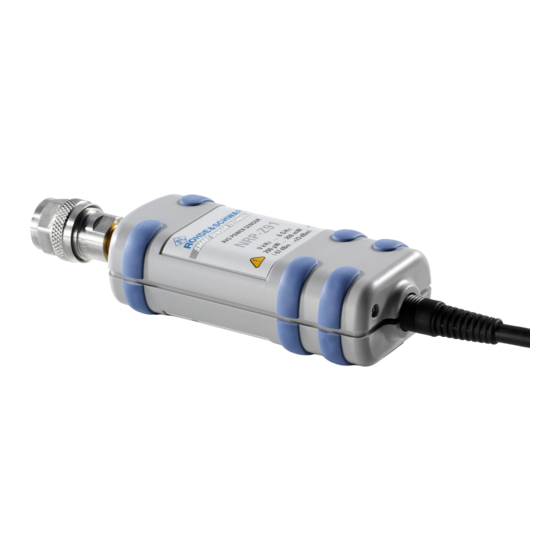
- Page 2 Operating Manual Average Power Sensor R&S NRP-Z91 1168.8004.02/.04 Test and Measurement 1168.8579.12-07-...
- Page 3 Dear Customer, R&S® is a registered trademark of Rohde & Schwarz GmbH & Co. KG Trade names are trademarks of the owners. 1168.8579.12-07-...
- Page 4 Basic Safety Instructions Always read through and comply with the following safety instructions! All plants and locations of the Rohde & Schwarz group of companies make every effort to keep the safety standards of our products up to date and to offer our customers the highest possible degree of safety. Our products and the auxiliary equipment they require are designed, built and tested in accordance with the safety standards that apply in each case.
- Page 5 Basic Safety Instructions Symbol Meaning Symbol Meaning Warning! Hot surface Alternating current (AC) Protective conductor terminal Direct/alternating current (DC/AC) Ground Device fully protected by double (reinforced) insulation Ground terminal EU labeling for batteries and accumulators For additional information, see section "Waste disposal/Environmental protection", item 1.
- Page 6 Basic Safety Instructions Operating states and operating positions The product may be operated only under the operating conditions and in the positions specified by the manufacturer, without the product's ventilation being obstructed. If the manufacturer's specifications are not observed, this can result in electric shock, fire and/or serious personal injury or death. Applicable local or national safety regulations and rules for the prevention of accidents must be observed in all work performed.
- Page 7 Basic Safety Instructions 6. The product may be operated only from TN/TT supply networks fuse-protected with max. 16 A (higher fuse only after consulting with the Rohde & Schwarz group of companies). 7. Do not insert the plug into sockets that are dusty or dirty. Insert the plug firmly and all the way into the socket provided for this purpose.
- Page 8 Basic Safety Instructions 2. Before you move or transport the product, read and observe the section titled "Transport". 3. As with all industrially manufactured goods, the use of substances that induce an allergic reaction (allergens) such as nickel cannot be generally excluded. If you develop an allergic reaction (such as a skin rash, frequent sneezing, red eyes or respiratory difficulties) when using a Rohde &...
- Page 9 Basic Safety Instructions 2. Adjustments, replacement of parts, maintenance and repair may be performed only by electrical experts authorized by Rohde & Schwarz. Only original parts may be used for replacing parts relevant to safety (e.g. power switches, power transformers, fuses). A safety test must always be performed after parts relevant to safety have been replaced (visual inspection, protective conductor test, insulation resistance measurement, leakage current measurement, functional test).
- Page 10 Instrucciones de seguridad elementales Waste disposal/Environmental protection 1. Specially marked equipment has a battery or accumulator that must not be disposed of with unsorted municipal waste, but must be collected separately. It may only be disposed of at a suitable collection point or via a Rohde &...
- Page 11 Instrucciones de seguridad elementales Se parte del uso correcto del producto para los fines definidos si el producto es utilizado conforme a las indicaciones de la correspondiente documentación del producto y dentro del margen de rendimiento definido (ver hoja de datos, documentación, informaciones de seguridad que siguen). El uso del producto hace necesarios conocimientos técnicos y ciertos conocimientos del idioma inglés.
- Page 12 Instrucciones de seguridad elementales Símbolo Significado Símbolo Significado Aviso: Cuidado en el manejo de dispositivos Distintivo de la UE para la eliminación por sensibles a la electrostática (ESD) separado de dispositivos eléctricos y electrónicos Más información en la sección "Eliminación/protección del medio ambiente", punto 2.
- Page 13 Instrucciones de seguridad elementales 1. Si no se convino de otra manera, es para los productos Rohde & Schwarz válido lo que sigue: como posición de funcionamiento se define por principio la posición con el suelo de la caja para abajo, modo de protección IP 2X, uso solamente en estancias interiores, utilización hasta 2000 m sobre el nivel del mar, transporte hasta 4500 m sobre el nivel del mar.
- Page 14 Instrucciones de seguridad elementales 6. Solamente está permitido el funcionamiento en redes de alimentación TN/TT aseguradas con fusibles de 16 A como máximo (utilización de fusibles de mayor amperaje solo previa consulta con el grupo de empresas Rohde & Schwarz). 7.
- Page 15 Instrucciones de seguridad elementales Funcionamiento 1. El uso del producto requiere instrucciones especiales y una alta concentración durante el manejo. Debe asegurarse que las personas que manejen el producto estén a la altura de los requerimientos necesarios en cuanto a aptitudes físicas, psíquicas y emocionales, ya que de otra manera no se pueden excluir lesiones o daños de objetos.
- Page 16 Instrucciones de seguridad elementales Reparación y mantenimiento 1. El producto solamente debe ser abierto por personal especializado con autorización para ello. Antes de manipular el producto o abrirlo, es obligatorio desconectarlo de la tensión de alimentación, para evitar toda posibilidad de choque eléctrico. 2.
- Page 17 Instrucciones de seguridad elementales 2. Las asas instaladas en los productos sirven solamente de ayuda para el transporte del producto por personas. Por eso no está permitido utilizar las asas para la sujeción en o sobre medios de transporte como p. ej. grúas, carretillas elevadoras de horquilla, carros etc. Es responsabilidad suya fijar los productos de manera segura a los medios de transporte o elevación.
- Page 18 Quality management Certified Quality System ISO 9001 and environmental Certified Environmental System management ISO 14001 Sehr geehrter Kunde, Dear customer, Cher client, Sie haben sich für den Kauf You have decided to buy a Vous avez choisi d’acheter un eines Rohde & Schwarz Produk- Rohde &...
- Page 19 Customer Support Technical support – where and when you need it For quick, expert help with any Rohde & Schwarz equipment, contact one of our Customer Support Centers. A team of highly qualified engineers provides telephone support and will work with you to find a solution to your query on any aspect of the operation, programming or applications of Rohde &...
- Page 20 R&S NRP-Z91 Table of Contents Chapter 1 Table of Contents Putting into Operation ......................1.1 Unpacking the power sensor ......................1.1 Connecting the power sensor ......................1.1 Operation with the R&S NRP/NRP2 power meter .................1.1 Connecting the power sensor .....................1.1 PC control ............................1.2 Hardware and software requirements ..................1.2 Operation via the R&S NRP-Z4 passive USB adapter ...............1.3 Connecting the sensor to the DUT .....................1.4...
- Page 21 List of Figs. Chapter 1 R&S NRP-Z91 Figs. Fig. 1-1 Displaying the total available power of a USB port ............1.3 Fig. 1-2 Configuration with Passive USB Adapter R&S NRP-Z4 ............ 1.3 Fig. 1-3 Configuration with Active USB Adapter R&S NRP-Z3 ............1.4 Fig.
- Page 22 R&S NRP-Z91 Unpacking the power sensor 1 Putting into Operation Follow the instructions below precisely to prevent damage to the power sensor – NOTICE particularly when you are putting it into operation for the first time. Unpacking the power sensor Remove the power sensor from its packing and check that nothing is missing.
- Page 23 PC control R&S NRP-Z91 PC control Hardware and software requirements The following requirements must be met if the power sensor is to be controlled by a PC via an interface adapter: The PC must have a USB port. Either Microsoft Windows XP (32 Bit), Microsoft Windows Vista (32 or 64 Bit), Microsoft Windows 7 (32 or 64 Bit), or x86 Linux (with kernel 2.6.8 oder more recent) must be installed as the operating system of the PC.
- Page 24 R&S NRP-Z91 PC control In the Windows™ start menu, select Settings – Control Panel Select the System icon Select the Hardware tab By clicking on the button with that name, start the Device Manager Open USB Controller (all USB controllers, hubs and USB devices are listed here) ...
- Page 25 PC control R&S NRP-Z91 Connecting the sensor to the DUT The power sensor R&S NRP-Z91 has a male N connector and so can be connected to any standard female N connector. Using light pressure, and keeping the male N connector perpendicular, insert it into the female N connector and tighten the N connector locking nut (right-hand thread).
- Page 26 R&S NRP-Z91 PC control The plug-in power supply is short-circuit-proof and has an internal fuse. It is not possible to replace this fuse or open the plug-in power supply. NOTICE The plug-in power supply is not intended for outdoor use. Keep within the temperature range of 0°C to 50°C.
- Page 27 PC control R&S NRP-Z91 Ports and LEDs The power sensors are connected to the front panel of the R&S NRP-Z5. The ports and LEDs on the front panel of the R&S NRP-Z5 are shown in Fig. 1-5. 1–4 Sockets for connecting the power sensors 5–8 Green LEDs for indicating normal operation 9–12...
- Page 28 R&S NRP-Z91 PC control Unlatch the R&S Instrument connector on the rear panel by pressing down the unlatching ring of the built-in plug and pulling off the cable jack at the same time (Fig. 1-7). Fig. 1-7 Unlatching the R&S Instrument connector Test Setup Fig.
- Page 29 PC control R&S NRP-Z91 Fig. 1-8 Typical test setup with R&S NRP-Z5 and PC 1168.8579.12...
- Page 30 R&S NRP-Z91 PC control Troubleshooting A frequent problem, especially in the case of operation under Microsoft Windows XP, is that the R&S NRP-Z5 fails to respond after a power sensor connected to the R&S NRP-Z5 is disconnected and reconnected. It is then necessary to restart the PC. This problem is not specific to the R&S NRP-Z5, but occurs with all USB hubs.
- Page 31 Operation with other Rohde & Schwarz test instruments R&S NRP-Z91 4. Double-clicking USB Root Hub opens the USB Root Hub Properties dialog box. Select the Power Management tab. Remove the check mark next to Allow the computer to turn off this device to save power and confirm this with OK.
- Page 32 R&S NRP-Z91 Table of Contents Chapter 2 Table of Contents Virtual Power Meter ......................2.1 Overview............................2.1 Menus ............................2.3 1168.8579.12 I-2.1...
- Page 33 List of Figs. and Tables Chapter 2 R&S NRP-Z91 Figs. Fig. 2-1 Power Viewer virtual power meter ...................2.1 Tables Table 2-1 Virtual power meter keys ....................2.2 Table 2-2 Virtual power meter entry fields ..................2.2 1168.8579.12 I-2.2...
- Page 34 R&S NRP-Z91 Overview 2 Virtual Power Meter You will find the NrpFlashup program that enables you to operate the power sensor with a PC under Windows™ on the CD-ROM that accompanies the power sensor. The program comprises several modules which can be started centrally via the Windows™ start-menu entry NRP Toolkit. This section describes the Power Viewer program module.
- Page 35 Overview R&S NRP-Z91 Table 2-1 Virtual power meter keys Button Function Key combination Exit Terminates the program. The current settings are saved and recalled the Alt + E next time the program is started. Selects Watt as the display unit. Alt + W Selects dBm as the display unit.
- Page 36 R&S NRP-Z91 Overview Menus The menu bar can be used to call less frequently used functions. File Start Log ... Opens a file-selection dialog to specify the path and name of the log file. Clicking the Save button starts the recording.
- Page 37 Overview R&S NRP-Z91 Simulation … Allows you to try out the functions virtual power meter even without power sensor. display alternates between Measurement Value 1 & Measurement Value 2 with a period given by Interval. Simulation can be activated immediately with the Activate check box.
-
Page 38: Table Of Contents
R&S NRP-Z91 Table of Contents Chapter 3 Table of Contents Manual Operation .......................3.1 Program module "Terminal" ......................3.1 Main control elements.........................3.1 Menus ............................3.3 Program module "Firmware Update" .....................3.6 Program module "Update S-Parameters" ..................3.6 Fundamentals ..........................3.6 Procedure ...........................3.9 1168.8579.12 I-3.1... - Page 39 List of Figs. and Tables Chapter 3 R&S NRP-Z91 Figs. Fig. 3-1 Sending commands using the Input field .................3.1 Fig. 3-2 Sending commands using command files ................3.2 Fig. 3-3 Dialog window for loading an s-parameter table...............3.9 Fig. 3-4 Dialog window for loading the backup file of a calibration data set ........3.10 Fig.
-
Page 40: Manual Operation
R&S NRP-Z91 Program module "Terminal" 3 Manual Operation The previous section describes the Power Viewer program module supplied with the instrument. This module simplifies the most frequently used function of a power meter – measuring the average power of an RF signal of almost any modulation. Other program modules are also part of the supplied equipment and can be selected in the Start menu: •... - Page 41 Program module "Terminal" R&S NRP-Z91 Fig. 3-2 Sending commands using command files Table 3-1 Buttons assigned to the Input field Button Function Key combination Send Sends the content of the Input entry field to the sensor. Alt + S With Loop the command or command sequence is cyclically sent. Pressing Loop Alt + L the button again terminates the cyclic transmission.
-
Page 42: Menus
R&S NRP-Z91 Program module "Terminal" A command line starting with a tab, a blank or a special character is considered a comment and not forwarded to the sensor. Measurement results, parameters and status information returned by the sensor are displayed in the Output field. - Page 43 Program module "Terminal" R&S NRP-Z91 Filtering is started with Apply. The number of lines matching the filter criterion is displayed in the Linecounter field. If Open on startup is active, the Output Postfilter dialog is automatically opened when the terminal is started. The dialog window is closed with OK. Response Opens the Response time dialog window where the response time of Time …...
- Page 44 R&S NRP-Z91 Program module "Terminal" Options Protocol Mode In this mode, a time stamp is added to each response block. Hex Mode In this mode, the response blocks from the sensor are displayed in hexadecimal format. Auto Delete With this option active, the Output field is automatically cleared when the Send button is pressed.
-
Page 45: Program Module "Firmware Update
Program module "Firmware Update" R&S NRP-Z91 Program module "Firmware Update" A detailed description of the program module for firmware updates is provided in the Service Manual. Program module "Update S-Parameters" Fundamentals With the power sensor R&S NRP-Z91, the influence of any twoport – e. g. an adapter – between the signal source and the sensor input can be considered, allowing the power P actually delivered by the signal source to be calculated. - Page 46 R&S NRP-Z91 Program module "Update S-Parameters" # [HZ | KHZ | MHZ | GHZ] [S] [MA | DB | RI] [R 50] 2. The measurement frequencies in ascending order are specified as follows: where is the display format as specified in the option line: (display format for linear magnitude and phase in degree) or (display format for magnitude in dB and phase in degree) (display format for real and imaginary part)
- Page 47 Program module "Update S-Parameters" R&S NRP-Z91 Structure of the uncertainty data file (square brackets indicate that the enclosed content is optional): 1. The option line has the following format: # [<frequency unit>] <parameter> [<format>] [<R n>] # identifies the option line. The <frequency unit>...
- Page 48 R&S NRP-Z91 Program module "Update S-Parameters" Procedure To load an s-parameter table into the calibration set of the sensor, proceed as follows: 1. Connect the sensor to the USB port of the PC and start the program module Update S- Parameters.
- Page 49 Program module "Update S-Parameters" R&S NRP-Z91 During loading, the current calibration data set of the sensor is overwritten. To be on the safe side, a backup copy of the current calibration data set is therefore automatically stored before s-parameters are loaded.
- Page 50 R&S NRP-Z91 Program module "Update S-Parameters" Fig. 3-5 Subsequently changing the default behaviour of the s-parameter correction 1168.8579.12 3.11...
- Page 52 R&S NRP-Z91 Table of Contents Chapter 5 Table of Contents Remote Control – Fundamentals .................5.1 1168.8579.12 I-5.1...
- Page 54 R&S NRP-Z91 Remote Control – Fundamentals 5 Remote Control – Fundamentals Rohde & Schwarz recommends to utilize the VXI Plug & Play Driver for the remote control of R&S NRP power sensors. This driver can be found on the CD-ROM supplied with the sensor or downloaded in its most recent version via the internet (http://rohde-schwarz.com/).
- Page 56 R&S NRP-Z91 Table of Contents Chapter 6 Table of Contents Remote Control – Commands ..................6.1 Notation .............................6.1 Commands as per IEEE 488.2 ......................6.2 *IDN? – Identification Query .......................6.2 *RST – Reset ..........................6.2 *TRG – Trigger..........................6.2 *TST? – Self Test Query......................6.2 SCPI Commands..........................6.3 CALibration ..........................6.3 CALibration:DATA[?] <calibration data set as definite length block>...
- Page 57 Table of Contents Chapter 6 R&S NRP-Z91 SYSTem............................6.14 SYSTem:INFO? [Item] ....................6.14 SYSTem:INITialize......................6.15 SYSTem:MINPower?....................6.16 SYSTem:RUTime[?] 0.0 to 10.0 .................6.16 SYSTem:SUTime[?] 0.0 to 10.0 .................6.16 SYSTem:TRANsaction:BEGin ..................6.16 SYSTem:TRANsaction:END..................6.16 TEST............................6.17 TEST:SENSor?......................6.17 TRIGger ............................6.18 ABORt ...........................6.18 INITiate:CONTinuous[?] OFF | ON ................6.18 INITiate:IMMediate......................6.19 TRIGger:COUNt[?] 1 to 2 ..................6.19 TRIGger:DELay[?] 0 to 100.0 ..................6.19 TRIGger:DELay:AUTO[?] OFF | ON................6.20...
- Page 58 List of Figures and Tables Chapter 6 R&S NRP-Z91 Figs. Fig. 6-1 Correction of interactions between the power sensor and the signal source ....6.12 Fig. 6-2 Correction of interactions between the power sensor, the signal source, and the s-parameter device ....................6.13 Tables Table 6-1 Commands of the CALibration system ................6.3...
-
Page 60: Remote Control - Commands
R&S NRP-Z91 Remote Control - Commands 6 Remote Control – Commands Notation In the following sections, all commands implemented in the sensor are first listed in a table according to command systems and are then described in detail. The notation is largely in line with the SCPI standard. -
Page 61: Commands As Per Ieee 488.2
Remote Control - Commands R&S NRP-Z91 Commands as per IEEE 488.2 The sensor supports a subset of the possible setting commands and queries (Common Commands and Queries) in line with IEEE 488.2. *IDN? – Identification Query *IDN? returns a string with information on the sensor's identity (device identification code). In addition, the version number of the installed firmware is indicated. -
Page 62: Scpi Commands
R&S NRP-Z91 Remote Control - Commands SCPI Commands The sensor R&S NRP-Z91 is controlled via the groups of commands • CALibration (zeroing) • SENSe (measurement configurations) • SYSTem • TRIGger • SERVice. CALibration Table 6-1 Commands of the CALibration system Command Parameter Unit... -
Page 63: Calibration:zero:auto[?] Off | On | Once
Remote Control - Commands R&S NRP-Z91 CALibration:ZERO:AUTO[?] OFF | ON | ONCE The commands CALibration:ZERO:AUTO ON and CALibration:ZERO:AUTO ONCE zeroes the three measurement paths of the sensor. For this purpose, the test signal must be deactivated or the sensor disconnected from the signal source. The sensor automatically detects the presence of any significant power to be measured. -
Page 64: Sense (Sensor Configuration)
R&S NRP-Z91 Remote Control - Commands SENSe (Sensor Configuration) The sensor is configured by means of the commands of the groups SENSe and TRIGger. Table 6-2 Commands of the SENSe system Command Parameter Unit Remarks SENSe :AVERage :COUNt[?] 1 to 65536 :AUTO[?] OFF | ON | ONCE :TYPE[?]... -
Page 65: Sense:average:count[?] 1 To 65536
Remote Control - Commands R&S NRP-Z91 Command Parameter Unit Remarks :SMOothing:STATe[?] OFF | ON :RANGe[?] 0 to 2 :RANGe:AUTO[?] OFF | ON :RANGe:CLEVel[?] –20.0 to 0.0 :SGAMma :CORRection:STATe[?] OFF | ON :MAGNitude[?] 0.0 to 1.0 :PHASe[?] –360.0 to 360.0 degree SENSe:AVERage:COUNt[?] 1 to 65536 SENSe:AVERage:COUNt sets the number of measured values that have to be averaged for forming the measurement result. -
Page 66: Sense:average:count:auto:mtime[?] 0.01 To 999.99
R&S NRP-Z91 Remote Control - Commands SENSe:AVERage:COUNt:AUTO:MTIMe[?] 0.01 to 999.99 SENSe:AVERage:COUNt:AUTO:MTIMe sets an upper limit for the settling time of the auto-averaging filter in the NSRatio mode and thus limits the length of the filter. The query returns the time that has been set. Default setting: 4.0 [s] SENSe:AVERage:COUNt:AUTO:NSRatio[?] 0.0 to 1.0 SENSe:AVERage:COUNt:AUTO:NSRatio determines the relative noise component in the measurement... -
Page 67: Sense:average:state[?] Off
Remote Control - Commands R&S NRP-Z91 apparent. However, this procedure does not shorten the measurement time required in order for the averaging filter to settle completely. SENSe:AVERage:STATe[?] OFF | ON SENSe:AVERage:STATe switches on or off the averaging filter. The query yields •... -
Page 68: Sense:correction:offset[?] -200.0 To 200.0
R&S NRP-Z91 Remote Control - Commands SENSe:CORRection:OFFSet[?] –200.0 to 200.0 SENSe:CORRection:OFFSet defines a fixed offset in dB, which is used to correct the measured value. (When a log scale is used, the offset is added to the measured value; this is the reason why the command has this name.) The attenuation of an attenuator located ahead of the sensor or the coupling attenuation of a directional coupler is taken into account with a positive offset, i.e. -
Page 69: Sense:function[?]
Remote Control - Commands R&S NRP-Z91 SENSe:FUNCtion[?] <sensor_function> In contrast to other sensors, the R&S NRP-Z91 only implements the Continuous Average mode. Therefore, the command SENSe:FUNCtion <sensor_function> only accepts the parameter "POWer:AVG". Table 6-3 Measurement mode "POWer:AVG" <sensor_function> Description of the measurement mode Continuous Average "POWer:AVG"... -
Page 70: Sense:power:avg:buffer:state[?] Off
R&S NRP-Z91 Remote Control - Commands SENSe:POWer:AVG:BUFFer:STATe[?] OFF | ON The buffered Continuous Average mode is activated with ON and deactivated with OFF. In this mode, the results generated by trigger events are collected in the sensor until the buffer is filled. All results are then transferred as block data. -
Page 71: Sense:range:auto[?] Off
Remote Control - Commands R&S NRP-Z91 If the measurement path is selected manually (SENSe:RANGe:AUTO OFF), the currently selected measurement path is output. With automatic selection, the last path that was set manually is output. Since this setting has been saved, it is immediately reset after deactivating the automatic function. Default setting: 2 (least sensitive path) SENSe:RANGe:AUTO[?] OFF | ON SENSe:RANGe:AUTO ON activates the automatic selection of the measurement path and... -
Page 72: Sense:sgamma:magnitude[?] 0.0 To 1.0
R&S NRP-Z91 Remote Control - Commands Fig. 6-2 Correction of interactions between the power sensor, the signal source, and the s- parameter device The query yields • 1 for OFF, • 2 for ON. Default setting: OFF SENSe:SGAMma:MAGNitude[?] 0.0 to 1.0 SENSe:SGAMma:MAGNitude defines the magnitude of the complex reflection coefficient of the signal source. -
Page 73: System
Remote Control - Commands R&S NRP-Z91 SYSTem With the aid of the SYSTem system, administrative device settings can be defined and queried. This includes detailed information on the sensor and its initialization and the transfer of available commands and their parameter limits. Table 6-4 Commands of the SYSTem system Command... -
Page 74: System:initialize
R&S NRP-Z91 Remote Control - Commands Item Information string Remarks "TECHNOLOGY" "3 Path Diode" Detector technology used "FUNCTION" "Power Terminating" The R&S NRP-Z91 is a terminating power sensor. "MINPOWER" "<nominal lower test limit in W>" The nominal lower test limit of the R&S NRP-Z91 is 200 pW, i.e. -
Page 75: System:minpower
Remote Control - Commands R&S NRP-Z91 SYSTem:MINPower? SYSTem:MINPower? yields the lower test limit of the sensor or the combination comprising the sensor and components connected ahead of it, if the SENSe:CORRection:SPDevice parameter has the ON value. This query can be used to determine a useful resolution for the result display near the lower test limit. -
Page 76: Test
R&S NRP-Z91 Remote Control - Commands TEST Table 6-6 Commands of the TEST system Command Parameter Unit Remarks TEST:SENSor? Query only TEST:SENSor? TEST:SENSor? triggers a selftest of the sensor. In contrast to *TST, this command yields detailed information, which is useful for troubleshooting. No signal may be applied to the sensor while the selftest is running. -
Page 77: Trigger
Remote Control - Commands R&S NRP-Z91 TRIGger Table 6-7 Commands of the TRIGger system Command Parameter Unit Remarks ABORt No query INITiate :CONTinuous[?] OFF | ON :IMMediate No query TRIGger :COUNt[?] 1 to 2 :DELay[?] 0 to 100.0 :AUTO[?] OFF | ON :HOLDoff[?] 0.0 to 10.0 :HYSTeresis[?]... -
Page 78: Initiate:immediate
R&S NRP-Z91 Remote Control - Commands The query yields • 1 for OFF, • 2 for ON. Default setting: OFF INITiate:IMMediate INITiate:IMMediate starts a single measurement cycle. The sensor first changes from the IDLE state to the WAIT_FOR_TRIGGER state and begins the measurement as soon as the trigger condition is fulfilled. -
Page 79: Trigger:delay:auto[?] Off
Remote Control - Commands R&S NRP-Z91 TRIGger:DELay:AUTO[?] OFF | ON TRIGger:DELay:AUTO ON ensures by means of an automatically determined delay that a measurement is only started after the sensor has settled. The power sensor R&S NRP-Z91 needs up to 20 ms to fully settle after a sharp change of the input power. If the automatic trigger delay was activated with the TRIGger:DELay:AUTO ON command, it has the following effect: After exiting the WAIT_FOR_TRIGGER state –... -
Page 80: Trigger:level[?] X To
R&S NRP-Z91 Remote Control - Commands TRIGger:LEVel[?] x to y TRIGger:LEVel sets the trigger threshold for internal triggering derived from the test signal (in W). This setting is irrelevant to all other trigger sources. If an s-parameter device is active and/or if a component with a global offset upstream from the sensor is considered, the currently effective trigger threshold as well as a trigger threshold to be input are referenced to the appropriately shifted sensor interface. - Page 81 Remote Control - Commands R&S NRP-Z91 The query yields • 1 for HOLD, • 2 for IMMediate, • 4 for INTernal, • 8 for BUS, • 16 for EXTernal. Default setting: IMMediate 1168.8579.12 6.22...
-
Page 82: List Of Remote-Control Commands
R&S NRP-Z91 Remote Control - Commands List of Remote-Control Commands The remote-control commands of the R&S NRP-Z91 have a syntax based on standard SCPI 1999.0, but they comply with it only to a limited extent. Table 6-8 List of remote-control commands Command Parameter Unit... - Page 83 Remote Control - Commands R&S NRP-Z91 Command Parameter Unit Default setting Page SENSe:CORRection:OFFSet:STATe[?] OFF | ON SENSe:CORRection:SPDevice:STATe[?] OFF | ON OFF (can be modified by the user) SENSe:FREQuency[?] 9.0e3 to 6.0e9 50.0e6 SENSe:FUNCtion[?] "POWer:AVG" "POWer:AVG" 6.10 SENSe:POWer:AVG:APERture[?] 10.0e–6 to 0.3 0.02 6.10 SENSe:POWer:AVG:BUFFer:SIZE[?]...
- Page 84 R&S NRP-Z91 Remote Control - Commands Command Parameter Unit Default setting Page INITiate:IMMediate 6.19 TRIGger:COUNt[?] 1 to 2 6.18 TRIGger:DELay[?] 0 to 100.0 6.19 TRIGger:DELay:AUTO[?] OFF | ON 6.20 TRIGger:HOLDoff[?] 0.0 to 10.0 6.20 TRIGger:HYSTeresis[?] 0.0 to 10.0 6.20 TRIGger:IMMediate 6.20 TRIGger:LEVel[?] x to y...
Need help?
Do you have a question about the R&S NRP-Z91 and is the answer not in the manual?
Questions and answers