
Related Manuals for Rohde & Schwarz NRP-Z28


Summary of Contents for Rohde & Schwarz NRP-Z28
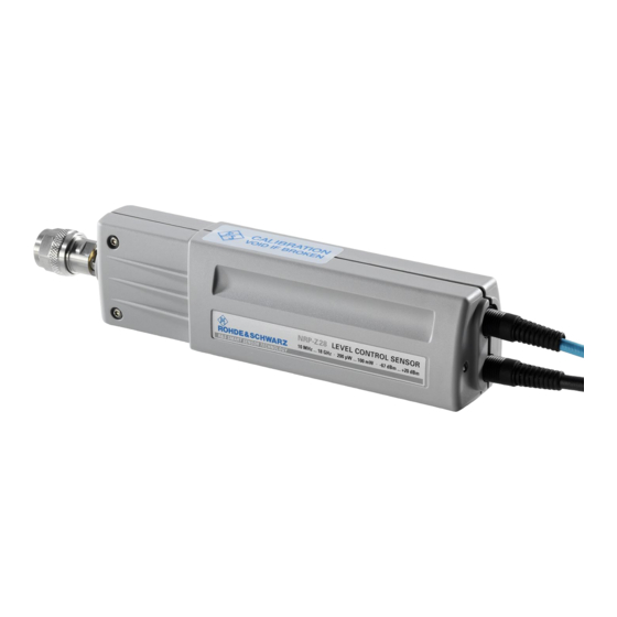
- Page 1 Operating Manual Level Control Sensor R&S NRP-Z28 1170.8008.02 R&S NRP-Z98 1170.8508.02 Test and Measurement 1170.8966.12-08...
- Page 2 Dear Customer, R&S® is a registered trademark of Rohde & Schwarz GmbH & Co. KG Trade names are trademarks of the owners. 1170.8966.12-08...
- Page 3 R&S NRP-Z28/Z98 Safety Information Safety Information Safety information is part of the product documentation. It warns you of potential dangers and gives instructions on how to prevent personal injury or damage caused by dangerous situations. Safety information is provided as follows: •...
- Page 5 R&S NRP-Z28/-Z98 Table of Contents Chapter 1 Table of Contents Putting into Operation ......................1.1 Unpacking the sensor ........................1.1 Connecting the sensor ........................1.1 Operation with the R&S NRP/NRP2 power meter .................1.3 Connecting the power sensor .....................1.3 Performing measurements ......................1.4 PC control ............................1.5 Hardware and software requirements ..................1.5...
- Page 6 List of Figs. Chapter 1 R&S NRP-Z28/-Z98 Figs. Fig. 1-1 Configuration with the R&S NRP/NRP2 ................1.4 Fig. 1-2 Displaying the total available power of a USB port ............1.6 Fig. 1-3 Power measurement on PC with the R&S NRP-Z4 passive USB adapter ......1.7 Fig.
- Page 7 R&S NRP-Z28/-Z98 Connecting the sensor 1 Putting into Operation Follow the instructions below precisely to prevent damage to the sensor – particularly NOTICE when you are putting the power sensor into operation for the first time. Unpacking the sensor Remove the power sensor from its packing and check that nothing is missing. Inspect all items for damage.
- Page 8 Connecting the sensor R&S NRP-Z28/-Z98 Do not apply excessive mechanical force to the RF connectors of the R&S NRP-Z28/-Z98 and DUT! 1170.8966.12...
- Page 9 R&S NRP-Z28/-Z98 Connecting the sensor Make sure the bending radius of the RF connecting cable is at least 50 mm! > 100 mm A tighter bend can permanently impair the matching of the RF input! Operation with the R&S NRP/NRP2 power meter Connecting the power sensor The power sensor can be connected to the R&S NRP/NRP2 base unit when it is in operation.
- Page 10 Configuration with the R&S NRP/NRP2 Performing measurements The R&S NRP-Z28/-Z98 power sensors behave in a similar manner as the R&S NRP-Z21 and R&S NRP-Z91 multipath diode sensors. Unlike these, however, instead of the power fed to the sensor, the power P supplied to the DUT is measured. By means of the S-parameter correction function, adapters or attenuators connected ahead of the DUT can be taken into consideration.
- Page 11 R&S NRP-Z28/-Z98 Connecting the sensor PC control Hardware and software requirements The following requirements must be met if the power sensor is to be controlled by a PC via an interface adapter: The PC must have a USB port.
- Page 12 Connecting the sensor R&S NRP-Z28/-Z98 In the Windows™ start menu, select Settings – Control Panel Select the System icon Select the Hardware tab By clicking on the button of that name, start the Device Manager ...
- Page 13 R&S NRP-Z28/-Z98 Connecting the sensor Operation via the R&S NRP-Z4 passive USB adapter Fig. 1-3 is a schematic of the measurement setup. The order in which the cables are connected is not critical. R&S NRP-Z4 R&S NRP-Z28/-Z98 Fig. 1-3 Power measurement on PC with the R&S NRP-Z4 passive USB adapter Operation via the R&S NRP-Z3 active USB adapter...
- Page 14 Connecting the sensor R&S NRP-Z28/-Z98 Fig. 1-5 Changing the primary adapter The plug-in power supply is short-circuit-proof and has an internal fuse. It is not possible to replace this fuse or open the plug-in power supply. NOTICE The plug-in power supply is not intended for outdoor use.
- Page 15 R&S NRP-Z28/-Z98 Connecting the sensor Operation via the R&S NRP-Z5 Sensor Hub The R&S NRP-Z5 sensor hub allows up to four power sensors to be operated on one PC. It combines the following functions: 4-port USB 2.0 hub ...
- Page 16 Connecting the sensor R&S NRP-Z28/-Z98 Ports and LEDs The power sensors are connected to the front panel of the R&S NRP-Z5. The ports and LEDs on the front panel of the R&S NRP-Z5 are shown in Fig. 1-6. 1–4 Sockets for connecting the power sensors 5–8...
- Page 17 R&S NRP-Z28/-Z98 Connecting the sensor Unlatch the R&S Instrument connector on the rear panel by pressing down the unlatching ring of the built-in plug and pulling off the cable jack at the same time (Fig. 1-8). Fig. 1-8 Unlatching the R&S Instrument connector Test Setup Fig.
- Page 18 Connecting the sensor R&S NRP-Z28/-Z98 Fig. 1-9 Typical test setup with R&S NRP-Z5 and PC 1170.8966.12 1.12...
- Page 19 R&S NRP-Z28/-Z98 Connecting the sensor Troubleshooting A frequent problem, especially in the case of operation under Microsoft Windows XP, is that the R&S NRP-Z5 fails to respond after a power sensor connected to the R&S NRP-Z5 is disconnected and reconnected. It is then necessary to restart the PC.
- Page 20 Performing measurements The R&S NRP-Z28/-Z98 power sensors behave in a similar manner as the R&S NRP-Z21 and R&S NRP-Z91 multipath diode sensors. Unlike these, however, instead of the power fed to the sensor, the power P supplied to the DUT is measured.
- Page 21 R&S NRP-Z28/-Z98 Connecting the sensor Operation with other Rohde & Schwarz test instruments Hardware and software requirements Many Rohde & Schwarz test instruments allow power measurements using power sensors of the R&S NRP-Zxx series. The power sensors are generally connected to the USB ports of the test instrument via one of the two interface adapters, R&S NRP-Z3 or R&S NRP-Z4, or the Sensor Hub...
- Page 23 R&S NRP-Z28/-Z98 Table of Contents Chapter 2 Table of Contents Virtual Power Meter ......................2.1 Overview............................2.1 Menus ............................2.3 1170.8966.12 I-2.1...
- Page 24 List of Figs. and Tables Chapter 2 R&S NRP-Z28/-Z98 Figs. Fig. 2-1 Power Viewer virtual power meter ...................2.1 Tables Table 2-1 Virtual power meter keys ....................2.2 Table 2-2 Virtual power meter entry fields ..................2.2 1170.8966.12 I-2.2...
- Page 25 R&S NRP-Z28/-Z98 Overview 2 Virtual Power Meter You will find the NrpFlashup program that enables you to operate the power sensor with a PC under Windows™ on the CD-ROM that accompanies the power sensor. The program comprises several modules which can be started centrally via the Windows™ start-menu entry NRP Toolkit.
- Page 26 Overview R&S NRP-Z28/-Z98 Table 2-1 Virtual power meter keys Button Function Key combination Exit Terminates the program. The current settings are saved and recalled the Alt + E next time the program is started. Selects Watt as the display unit.
- Page 27 R&S NRP-Z28/-Z98 Overview Menus The menu bar can be used to call less frequently used functions. File Start Log ... Opens a file-selection dialog to specify the path and name of the log file. Clicking the Save button starts the recording.
- Page 28 Overview R&S NRP-Z28/-Z98 Read Error Queue … Reads the error queue. All the error messages that have been issued since the last call are read line- by-line. A tick before this menu entry indicates that an error has occurred. Simulation …...
-
Page 29: Table Of Contents
R&S NRP-Z28/-Z98 Table of Contents Chapter 33 Table of Contents Manual Operation .......................3.1 Program module "Terminal" ......................3.1 Main control elements.........................3.1 Menus ............................3.3 Program module "Firmware Update" .....................3.6 Program module "Update S-Parameters" ..................3.6 Fundamentals ..........................3.6 Procedure ..........................3.10 1170.8966.12 I-3.1... - Page 30 List of Figs. and Tables Chapter 33 R&S NRP-Z28/-Z98 Figs. Fig. 3-1 Sending commands using the Input field .................3.1 Fig. 3-2 Sending commands using command files ................3.2 Fig. 3-3 Dialog window for loading an s-parameter table.............3.10 Fig. 3-4 Dialog window for loading the backup file of a calibration data set ........3.11 Fig.
-
Page 31: Manual Operation
R&S NRP-Z28/-Z98 Program module "Terminal" 3 Manual Operation The previous section describes the Power Viewer program module supplied with the instrument. This module simplifies the most frequently used function of a power meter – measuring the average power of an RF signal of almost any modulation. Other program modules are also part of the supplied equipment and can be selected in the Start menu: •... - Page 32 Program module "Terminal" R&S NRP-Z28/-Z98 Fig. 3-2 Sending commands using command files Table 3-1 Buttons assigned to the Input field Button Function Key combination Send Sends the content of the Input entry field to the sensor. Alt + S With Loop the command or command sequence is cyclically sent. Pressing...
-
Page 33: Menus
R&S NRP-Z28/-Z98 Program module "Terminal" A command line starting with a tab, a blank or a special character is considered a comment and not forwarded to the sensor. Measurement results, parameters and status information returned by the sensor are displayed in the Output field. - Page 34 Program module "Terminal" R&S NRP-Z28/-Z98 Filtering is started with Apply. The number of lines matching the filter criterion is displayed in the Linecounter field. If Open on startup is active, the Output Postfilter dialog is automatically opened when the terminal is started. The dialog window is closed with OK.
- Page 35 R&S NRP-Z28/-Z98 Program module "Terminal" Options Protocol Mode In this mode, a time stamp is added to each response block. Hex Mode In this mode, the response blocks from the power sensor are displayed in hexadecimal format. Auto Delete With this option active, the Output field is automatically cleared when the Send button is pressed.
-
Page 36: Program Module "Firmware Update
Program module "Update S-Parameters" Fundamentals With the R&S NRP-Z28/-Z98 sensors, the influence of any twoport – e.g. an adapter – between the sensor output and the DUT can be considered, allowing the power P actually fed to the DUT to be calculated. - Page 37 R&S NRP-Z28/-Z98 Program module "Update S-Parameters" Structure of the S2P measurement data file: 1. The option line has the following format (square brackets indicate that the enclosed content is optional): # [<frequency unit>] [<parameter>] [<format>] [<R n>] # identifies the option line.
- Page 38 Program module "Update S-Parameters" R&S NRP-Z28/-Z98 Table 3-5 Interpolated uncertainties of measurement frequencies for s-parameters (example) f in GHz unc [s (f)] 0.01 0.95 0.01 0.01 1.05 0.01 0.005 1.15 0.005 0.005 At 1.05 GHz, the higher uncertainty of the two adjacent 1.0 GHz and 1.1 GHz measurement frequencies is entered in the s-parameter table.
- Page 39 R&S NRP-Z28/-Z98 Program module "Update S-Parameters" NOTICE The upper nominal measurement limit of the sensor-twoport combination entered when loading the s-parameters should be carefully specified, as automatic test systems may evaluate it and an incorrect value may cause the sensor and/or the twoport to be overloaded.
-
Page 40: Procedure
Program module "Update S-Parameters" R&S NRP-Z28/-Z98 Procedure To load an s-parameter table into the calibration set of the sensor, proceed as follows: 1. Connect the sensor to the USB port of the PC and start the program module Update S- Parameters. - Page 41 R&S NRP-Z28/-Z98 Program module "Update S-Parameters" During loading, the current calibration data set of the sensor is overwritten. To be on the safe side, a backup copy of the current calibration data set is therefore automatically stored before s-parameters are loaded.
- Page 42 Program module "Update S-Parameters" R&S NRP-Z28/-Z98 Fig. 3-5 Subsequently changing the default behavior of the s-parameter correction 1170.8966.12 3.12...
- Page 43 R&S NRP-Z28/-Z98 Table of Contents Chapter 5 Table of Contents Remote Control – Fundamentals .................5.1 1170.8966.12 I-5.1...
- Page 45 R&S NRP-Z28/-Z98 Remote Control – Fundamentals 5 Remote Control – Fundamentals Rohde & Schwarz recommends to utilize the VXI Plug & Play Driver for the remote control of R&S NRP power sensors and power sensor modules. This driver can be found on the CD-ROM supplied with the sensor or downloaded in its most recent version via the internet (http://rohde-schwarz.com/).
- Page 47 SENSe:CORRection:DCYCle:STATe[?] OFF | ON ............6.11 SENSe:CORRection:OFFSet[?] –200.0 to 200.0 ............6.11 SENSe:CORRection:OFFSet:STATe[?] OFF | ON ............6.11 SENSe:CORRection:SPDevice:STATe[?] OFF | ON ..........6.12 SENSe:FREQuency[?] 10.0e6 to 18.0e9 (NRP-Z28), or 9.0e3 to 6.0e9 (NRP-Z98) ..6.12 SENSe:FUNCtion[?] <sensor_function>..............6.13 SENSe:POWer:AVG:APERture[?] 10e-6 to 0.3 ............6.14 SENSe:POWer:AVG:BUFFer:SIZE[?] 1 to 1024 ............6.14 SENSe:POWer:AVG:BUFFer:STATe[?] OFF | ON ............6.15...
- Page 48 Table of Contents Chapter 6 R&S NRP-Z28/-Z98 SENSe:SGAMma:CORRection:STATe[?] OFF | ON ..........6.17 SENSe:SGAMma:MAGNitude[?] 0.0 to 1.0..............6.18 SENSe:SGAMma:PHASe[?] –360.0 to 360.0.............6.18 SENSe:TIMing:EXCLude:STARt[?] 0.0 to 0.1 ..........6.19 SENSe:TIMing:EXCLude:STOP[?] 0.0 to –0.003 .........6.19 SENSe:TRACe:AVERage:COUNt[?] 1 to 8192 ..........6.20 SENSe:TRACe:AVERage:STATe[?] OFF | ON ..........6.20 SENSe:TRACe:AVERage:TCONtrol[?] MOVing | REPeat ......6.21...
- Page 49 Figures and List of Tables Chapter 6 R&S NRP-Z28/-Z98 Figs. Fig. 6-1 Effect of SENSe:POWer:BURSt:DTOLerance ...............6.16 Fig. 6-2 Correction of interactions between the power sensor and the DUT .......6.18 Fig. 6-3 Correction of interactions between the power sensor, the DUT, and the s-parameter device ....................6.18...
-
Page 51: Remote Control - Commands
• that are available as query only • that are only available with the R&S NRP-Z28 ( Indentations The various levels of the SCPI command hierarchy are shown in the table by indentations to the right. The lower the level, the greater the indentation to the right. - Page 52 Remote Control - Commands R&S NRP-Z28/-Z98 <parameter> A parameter or a variable in triangular brackets expresses its current value. <variable> This command is only available with the R&S NRP-Z28. 1170.8966.12...
-
Page 53: Commands As Per Ieee 488.2
*IDN? – Identification Query *IDN? returns a string with information on the sensor's identity (device identification code). In addition, the version number of the installed firmware is indicated. The string for a sensor of type R&S NRP-Z28 has the following structure: ROHDE&SCHWARZ,NRP-Z28,<serial number>,<firmware version>... -
Page 54: Scpi Commands
Remote Control - Commands R&S NRP-Z28/-Z98 SCPI Commands The R&S NRP-Z28/-Z98 sensors are controlled via the groups of commands • CALibration (zeroing) • SENSe (measurement configurations) • SYSTem • TRIGger • SERVice. CALibration Table 6-1 Commands of the CALibration system... -
Page 55: Calibration:zero:auto[?] Off | On | Once
R&S NRP-Z28/-Z98 Remote Control - Commands CALibration:ZERO:AUTO[?] OFF | ON | ONCE The commands CALibration:ZERO:AUTO ON and CALibration:ZERO:AUTO ONCE zeroes the three measurement paths of the sensor. For this purpose, the test signal must be deactivated or the sensor disconnected from the signal source. The sensor automatically detects the presence of any significant power to be measured. -
Page 56: Sense (Sensor Configuration)
:STATe[?] OFF to ON :OFFSet[?] -200.0 to 200.0 :STATe[?] OFF to ON :SPDevice:STATe[?] OFF to ON :FREQuency[?] 10.0e6 to 18.0e9 (NRP-Z28) or 9.0e3 to 6.0e9 (NRP-Z98) :FUNCtion[?] “POWer:AVG“ | “POWer:TSLot:AVG“ | “POWer:BURSt:AVG“ | “XTIME:POWer“(NRP-Z28) “POWer:AVG“ (NRP-Z98) :POWer :AVG :APERture[?] 10.0e-6 to 0.3 :BUFFer 1170.8966.12... - Page 57 R&S NRP-Z28/-Z98 Remote Control - Commands Command Parameter Unit Remarks :SIZE[?] 1 to 1024 :STATe[?] OFF | ON :SMOothing:STATe[?] OFF | ON :BURSt:DTOLerance[?] 0.0 to 3.0e-3 :TSLot:AVG :COUNt[?] 1 to 128 :WIDTh[?] 10.0e-6 to 0.1 :RANGe [?] 0 to 2...
-
Page 58: Sense:average:count[?] 1 To 65536
Remote Control - Commands R&S NRP-Z28/-Z98 SENSe:AVERage:COUNt[?] 1 to 65536 SENSe:AVERage:COUNt sets the number of measured values that have to be averaged for forming the measurement result in the modes Continuous Average, Burst Average and Timeslot Average. The higher this averaging factor, the less the measured values fluctuate and the longer the measurement time lasts. -
Page 59: Sense:average:count:auto:nsratio[?] 0.0
R&S NRP-Z28/-Z98 Remote Control - Commands SENSe:AVERage:COUNt:AUTO:NSRatio[?] 0.0 to 1.0 SENSe:AVERage:COUNt:AUTO:NSRatio determines the relative noise component in the measurement result for the Continuous Average, Burst Average and Timeslot Average modes if auto-averaging is operated in the corresponding mode (SENSe:AVERage:COUNt:AUTO:TYPE NSRatio). The noise component is defined as the magnitude of the level variation in dB caused by the inherent noise of the sensor (two standard deviations). -
Page 60: Sense:average:count:auto:type[?] Resolution | Nsratio
Remote Control - Commands R&S NRP-Z28/-Z98 SENSe:AVERage:COUNt:AUTO:TYPE[?] RESolution | NSRatio SENSe:AVERage:COUNt:AUTO:TYPE defines the automatic averaging filter mode in the Continuous Average, Burst Average and Timeslot Average modes. The RESolution parameter sets the mode usual for power meters; NSRatio predefines the compliance to an exactly defined noise component. -
Page 61: Sense:correction:dcycle[?] 0.001 To 99.999
R&S NRP-Z28/-Z98 Remote Control - Commands SENSe:CORRection:DCYCle[?] 0.001 to 99.999 SENSe:CORRection:DCYCle sets the duty cycle to a percent value for the correction of pulse- modulated signals. With the correction activated, the sensor calculates the signal pulse power from this value and the mean power. Since the duty cycle is only useful in the Continuous Average mode, it is evaluated only there. -
Page 62: Sense:correction:spdevice:state[?] Off
The factory-set default setting of the sensor is OFF. On loading an s-parameter table, the default setting can be redefined (see section 3). SENSe:FREQuency[?] 10.0e6 to 18.0e9 (NRP-Z28), or 9.0e3 to 6.0e9 (NRP-Z98) SENSe:FREQuency transfers the carrier frequency of the RF signal to be measured; this frequency is used for the frequency-response correction of the measurement result. -
Page 63: Sense:function[?]
R&S NRP-Z28/-Z98 Remote Control - Commands SENSe:FUNCtion[?] <sensor_function> SENSe:FUNCtion <sensor_function> sets the sensor to one of the following measurement modes: Table 6-3 Measurement modes <sensor_function> Description of the measurement mode Continuous Average "POWer:AVG" In this mode, the average power of the measurement signal is asynchronously measured within definable time intervals (sampling windows). -
Page 64: Sense:power:avg:aperture[?] 10E-6
Remote Control - Commands R&S NRP-Z28/-Z98 <sensor_function> Description of the measurement mode Trace "XTIMe:POWer" In the Trace mode, the envelope power can be recorded as a function to time. This is done by sampling power over a time interval that can be specified by the user (SENSe:TRACe:OFFSet:TIME and SENSe:TRACe:TIME commands), and then assigning the power values that have been determined to a number of pixels that are largely user-selectable (SENSe:TRACe:POINts command). -
Page 65: Sense:power:avg:buffer:state[?] Off
R&S NRP-Z28/-Z98 Remote Control - Commands SENSe:POWer:AVG:BUFFer:STATe[?] OFF | ON The buffered Continuous Average mode is activated with ON and deactivated with OFF. In this mode, the results generated by trigger events are collected in the sensor until the buffer is filled. All results are then transferred as block data. -
Page 66: Sense:power:tslot:avg:count[?] 1 To 128
Remote Control - Commands R&S NRP-Z28/-Z98 Power Trigger level Time Dropout time BURSt:DTOLerance BURSt:DTOLerance Pulse duration Fig. 6-1 Effect of SENSe:POWer:BURSt:DTOLerance SENSe:POWer:TSLot:AVG:COUNt[?] 1 to 128 For the Timeslot mode, SENSe:POWer:TSLot:AVG:COUNt sets the number of consecutive timeslots that are to be processed after each trigger event. -
Page 67: Sense:range:auto[?] Off
R&S NRP-Z28/-Z98 Remote Control - Commands If the measurement path is selected manually (SENSe:RANGe:AUTO OFF), the currently selected measurement path is output. With automatic selection, the last path that was set manually is output. Since this setting has been saved, it is immediately reset after deactivating the automatic function. -
Page 68: Sense:sgamma:magnitude[?] 0.0 To 1.0
Remote Control - Commands R&S NRP-Z28/-Z98 Fig. 6-2 Correction of interactions between the power sensor and the DUT If the gamma correction is made in connection with an s-parameter correction (setting SENSe:CORRection:SPDevice:STATe ON), the interaction of the DUT with the s-parameter device on the one hand and the output of the sensor on the other hand (depending on the magnitude of the term ) is corrected. -
Page 69: Sense:timing:exclude:start[?] 0.0
R&S NRP-Z28/-Z98 Remote Control - Commands SENSe:TIMing:EXCLude:STARt[?] 0.0 to 0.1 SENSe:TIMing:EXClude:STARt defines an exclusion time at the start of a measurement window in the Burst Average and Timeslot Average modes. It is indicated by T in Figs. 6-4 and 6-5. -
Page 70: Sense:trace:average:count[?] 1 To 8192
Remote Control - Commands R&S NRP-Z28/-Z98 Fig. 6-5 Effect of SENSe:TIMing:EXCLude:STARt and :STOP in the Timeslot Average mode SENSe:TRACe:AVERage:COUNt[?] 1 to 8192 SENSe:TRACe:AVERage:COUNt is used to set the averaging factor for the Trace mode. To put the setting into effect, you must also activate averaging for the Trace mode and deactivate the Realtime mode (settings SENSe:TRACe:AVERage:STATe ON and SENSe:TRACe:REALtime OFF). -
Page 71: Sense:trace:average:tcontrol[?] Moving | Repeat
R&S NRP-Z28/-Z98 Remote Control - Commands SENSe:TRACe:AVERage:TCONtrol[?] MOVing | REPeat SENSe:TRACe:AVERage:TCONtrol (terminal control) defines how the measurement results are to be output in the Trace mode if the averaging filter has been activated. The REPeat parameter specifies that a measurement result is not output until the entire measurement has been completed. -
Page 72: Sense:trace:points[?] 1 To 1024
Remote Control - Commands R&S NRP-Z28/-Z98 SENSe:TRACe:POINts[?] 1 to 1024 This command defines the time resolution of the measurement result. Each "point" represents a time interval whose duration is obtained from the trace length (command SENSe:TRACe:TIME) divided by N-1, where N is the number of "points". The measurement result for a "point" equals the average power over the associated time interval. -
Page 73: System
R&S NRP-Z28/-Z98 Remote Control - Commands SYSTem With the aid of the SYSTem system, administrative device settings can be defined and queried. This includes detailed information on the sensor and its initialization and the transfer of available commands and their parameter limits. - Page 74 "TECHNOLOGY" "3 Path Diode" Detector technology used "FUNCTION" "Power Source" The R&S NRP-Z28/-Z98 is a power sensor that functions as a source. "MINPOWER" "<nominal lower test limit in W>" The nominal lower test limit of the R&S NRP-Z28/-Z98 is 200 pW, i.e. with s-parameter correction deactivated, the sensor returns the information string "2e-10"...
-
Page 75: System:initialize
R&S NRP-Z28/-Z98 Remote Control - Commands Item Information string Remarks "CAL. S PARA." "<date>" Date of s-parameter calibration in the format YYYY-MM-DD. If no S parameter set is loaded, the sensor returns the string "not applicable". "Invalid Calibration Date" is returned with an invalid date entry. -
Page 76: System:transaction:begin
Remote Control - Commands R&S NRP-Z28/-Z98 SUTime is usually set to a value that is slightly smaller than the response time of the control system. Trigger events that have not yet occurred can then still be detected in time. At high trigger frequencies, the result is that after the start of the measurement, only the first changeover to the WAIT_FOR_TRIGGER state and the subsequent changeover to the MEASURING state are reported. -
Page 77: Test
R&S NRP-Z28/-Z98 Remote Control - Commands TEST Table 6-6 Commands of the TEST system Command Parameter Unit Remarks TEST:SENSor? Query only TEST:SENSor? TEST:SENSor? triggers a selftest of the sensor. In contrast to *TST, this command yields detailed information, which is useful for troubleshooting. -
Page 78: Trigger
Remote Control - Commands R&S NRP-Z28/-Z98 TRIGger Table 6-7 Commands of the TRIGger system Command Parameter Unit Remarks ABORt No query INITiate :CONTinuous[?] OFF | ON :IMMediate No query TRIGger :ATRigger:STATe[?] OFF | ON :COUNt[?] 1 to 2 :DELay[?] x to 100.0... -
Page 79: Initiate:immediate
R&S NRP-Z28/-Z98 Remote Control - Commands If the continuous measurement mode is switched off by means of the INITiate:CONTinuous OFF command, single measurements can be started with the INITiate:IMMediate command (see below). After triggering and completion of the measurement, the sensor enters the IDLE state and remains in this state until a new measurement is started with the INITiate:IMMediate command. -
Page 80: Trigger:delay[?] X To 100.0
20 ms to fully settle after a sharp change of the input power (negligible for the R&S NRP-Z28). If the automatic trigger delay was activated with the TRIGger:DELay:AUTO ON command, it has the following effect: After exiting the WAIT_FOR_TRIGGER state –... -
Page 81: Trigger:holdoff[?] 0.0
R&S NRP-Z28/-Z98 Remote Control - Commands TRIGger:HOLDoff[?] 0.0 to 10.0 TRIGger:HOLDoff suppresses trigger events within the set holdoff time (in s), starting from the time of the last successful triggering. The query yields the set holdoff time (in s). Default setting: 0.0 [s] TRIGger:HYSTeresis[?] 0.0 to 10.0... -
Page 82: Trigger:slope[?] Positive | Negative
Remote Control - Commands R&S NRP-Z28/-Z98 TRIGger:SLOPe[?] POSitive | NEGative TRIGger:SLOPe defines the edge of the trigger event with internal and external triggering in the Continuous Average, Timeslot Average, and Trace modes. In this connection, positive means increasing envelope power (with internal triggering) or increasing voltage (with external triggering). As in the Burst Average mode, this command has no effect in conjunction with trigger sources BUS, HOLD and IMMediate. -
Page 83: List Of Remote-Control Commands
R&S NRP-Z28/-Z98 Remote Control - Commands List of Remote-Control Commands The remote-control commands of the R&S NRP-Z28/-Z98 have a syntax based on standard SCPI 1999.0, but they comply with it only to a limited extent. Table 6-8 List of remote-control commands... - Page 84 SENSe Commands SENSe:CORRection:OFFSet:STATe[?] OFF | ON 6.11 SENSe:CORRection:SPDevice:STATe[?] OFF | ON OFF (can be 6.12 modified by the user) SENSe:FREQuency[?] 10.0e6 to 18.0e9 (NRP-Z28) or 50.0e6 6.12 9.0e3 to 6.0e9 (NRP-Z98) SENSe:FUNCtion[?] "POWer:AVG" | "POWer:AVG" 6.13 "POWer:TSLot:AVG" | "POWer:BURSt:AVG" | "XTIMe:POWer"...
- Page 85 R&S NRP-Z28/-Z98 Remote Control - Commands Command Parameter Unit Default setting Page SENSe Commands SENSe:TRACe:OFFSet:TIME[?] – (<TRIGger:DELay> + 0.005) to 6.21 100.0 SENSe:TRACe:POINts[?] 1 to 1024 6.22 SENSe:TRACe:REALtime[?] OFF | ON 6.22 SENSe:TRACe:TIME[?] 0.0001 to 0.3 0.01 6.22 SYSTem Commands SYSTem:INFO? [Item] 6.23...
- Page 86 Remote Control - Commands R&S NRP-Z28/-Z98 Command Parameter Unit Default setting Page Triggersystem Commands ABORt 6.28 INITiate:CONTinuous[?] OFF | ON 6.28 INITiate:IMMediate 6.29 TRIGger:ATRigger:STATe[?] OFF | ON 6.29 TRIGger:COUNt[?] 1 to 2 6.29 TRIGger:DELay[?] x to 100.0 6.30 TRIGger:DELay:AUTO[?] OFF | ON 6.30...
- Page 87 R&S NRP-Z28/Z98 Transporting 7 Transporting Packing Use the original packaging material. It consists of antistatic wrap for electrostatic protection and packing material designed for the product. If you do not have the original packaging, use similar materials that provide the same level of protection.
- Page 89 R&S NRP-Z28/Z98 Maintenance, Storage and Disposal 8 Maintenance, Storage and Disposal The product does not require regular maintenance. It only requires occasional cleaning. It is however advisable to check the nominal data from time to time. Regular Checks If the power sensor is used frequently, check the RF connectors for visible damage - bent inner conductors, broken contact springs and so on.
- Page 90 Maintenance, Storage and Disposal R&S NRP-Z28/Z98 Disposing Electrical and Electronic Equipment A product that is labeled as follows cannot be disposed of in normal household waste after it has come to the end of its service life. Even disposal via the municipal collection points for waste electrical and electronic equipment is not permitted.
Need help?
Do you have a question about the NRP-Z28 and is the answer not in the manual?
Questions and answers