Rohde & Schwarz NRP T Series User Manual
Thermal power sensors
Hide thumbs
Also See for NRP T Series:
- Getting started (52 pages) ,
- User manual (169 pages) ,
- Getting started (56 pages)
Table of Contents
Advertisement
Quick Links
Advertisement
Table of Contents

Subscribe to Our Youtube Channel
Related Manuals for Rohde & Schwarz NRP T Series


Summary of Contents for Rohde & Schwarz NRP T Series
- Page 1 ® R&S NRPxxT(N) Thermal Power Sensors User Manual (;ÛÊG2) 1177602302 Version 08...
- Page 2 This manual describes the following thermal power sensors with firmware version FW 02.30 and later: ● ® R&S NRP18T (1424.6115.02) ● ® R&S NRP18TN (1424.6121.02) ● ® R&S NRP33T (1424.6138.02) ● ® R&S NRP33TN (1424.6144.02) ● ® R&S NRP40T (1424.6150.02) ●...
-
Page 3: Table Of Contents
® Contents R&S NRPxxT(N) Contents 1 Safety Information..................9 2 Welcome....................10 Documentation Overview................... 10 2.1.1 Getting Started Manual....................10 2.1.2 User Manuals........................ 10 2.1.3 Tutorials.........................10 2.1.4 Instrument Security Procedures..................10 2.1.5 Basic Safety Instructions....................10 2.1.6 Data Sheets and Brochures..................11 2.1.7 Release Notes and Open Source Acknowledgment (OSA).......... - Page 4 ® Contents R&S NRPxxT(N) Trigger I/O Connector....................26 Host Interface......................26 Status LED........................26 LAN PoE Interface.......................27 5 Operating Concepts................29 R&S NRP Toolkit......................29 5.1.1 Versions and Downloads....................29 5.1.2 System Requirements....................29 5.1.3 R&S NRP Toolkit for Windows..................30 5.1.3.1 Components of the R&S NRP Toolkit................31 Browser-Based User Interface...................32 Remote Control......................
- Page 5 ® Contents R&S NRPxxT(N) 7.2.2 Using the Web User Interface..................58 7.2.3 Using Remote Control....................58 8 Replacing an R&S NRP‑Zxx with an R&S NRPxxT(N)...... 60 Most Important Differences..................60 Prerequisites....................... 60 9 Remote Control Commands..............62 Conventions Used in SCPI Command Descriptions..........62 Notations........................62 Common Commands....................
- Page 6 ® Contents R&S NRPxxT(N) 9.8.3 Configuring Corrections....................92 9.8.3.1 Duty Cycle Corrections....................92 9.8.3.2 Offset Corrections......................93 9.8.3.3 S-Parameter Correction....................94 9.8.3.4 S-Gamma Corrections....................96 9.8.3.5 I-Gamma Queries......................97 9.8.3.6 Using the S-Parameters Tool..................98 Calibrating, Zeroing....................108 9.10 Testing........................111 9.11 Configuring the System....................
- Page 7 ® Contents R&S NRPxxT(N) 11.2.5 Structure of a Command Line..................140 11.2.6 Responses to Queries....................141 11.3 Status Reporting System..................142 11.3.1 Hierarchy of the Status Registers................142 11.3.2 Structure of a SCPI Status Register................143 11.3.3 Status Byte (STB) and Service Request Enable Register (SRE)........144 11.3.4 IST Flag and Parallel Poll Enable Register (PPE)............
- Page 8 ® Contents R&S NRPxxT(N) User Manual 1177.6023.02 ─ 08...
-
Page 9: Safety Information
® Safety Information R&S NRPxxT(N) 1 Safety Information The product documentation helps you use the R&S NRPxxT(N) safely and efficiently. Follow the instructions provided here and in the printed "Basic Safety Instructions". Keep the product documentation nearby and offer it to other users. Intended use The R&S NRPxxT(N) is intended for the development, production and verification of electronic components and devices in industrial, administrative, and laboratory environ-... -
Page 10: Welcome
® Welcome R&S NRPxxT(N) Documentation Overview 2 Welcome This chapter provides an overview of the user documentation and an introduction to the R&S NRPxxT(N). 2.1 Documentation Overview This section provides an overview of the R&S NRPxxT(N) user documentation. Unless specified otherwise, you find the documents on the R&S NRPxxT(N) product page at: www.rohde-schwarz.com/product/nrp-t-tn 2.1.1 Getting Started Manual Introduces the R&S NRPxxT(N) and describes how to set up and start working with the... -
Page 11: Data Sheets And Brochures
® Welcome R&S NRPxxT(N) Key Features 2.1.6 Data Sheets and Brochures The data sheet contains the technical specifications of the R&S NRPxxT(N). It also lists the firmware applications and their order numbers, and optional accessories. The brochure provides an overview of the instrument and deals with the specific char- acteristics. -
Page 12: Preparing For Use
® Preparing for Use R&S NRPxxT(N) Considerations for Test Setup 3 Preparing for Use For information on safety, see: ● Chapter 1, "Safety Information", on page 9 ● Chapter 3.2, "Operating Conditions", on page 12 3.1 Unpacking and Checking the Power Sensor Check the equipment for completeness using the delivery note and the accessory lists for the various items. -
Page 13: Connecting To A Dut
® Preparing for Use R&S NRPxxT(N) Connecting to a DUT Ground yourself to avoid electrostatic discharge (ESD) damage: ● Using a wrist strap and cord, connect yourself to the ground. ● Use a conductive floor mat and heel strap combination. EMI impact on measurement results Electromagnetic interference (EMI) may affect the measurement results. -
Page 14: Connecting A Cable To The Host Interface
® Preparing for Use R&S NRPxxT(N) Connecting to a Controlling Host To disconnect from the DUT 1. NOTICE! Risk of damaging the center pin of the RF connector. Always rotate only the hex nut of the RF connector. Never rotate the power sensor itself. Carefully loosen the union nut at the front of the RF connector of the sensor. -
Page 15: Computer
® Preparing for Use R&S NRPxxT(N) Connecting to a Controlling Host 3.6.1 Computer If the controlling host is a computer, you can operate the power sensor using a suppor- ted software, the web user interface or remote control. For details, see Chapter 5, "Operating Concepts",... -
Page 16: R&S Nrp-Z5 Sensor Hub Setup
® Preparing for Use R&S NRPxxT(N) Connecting to a Controlling Host a) Connect the R&S NRP‑ZKU cable to the power sensor. "To connect a cable to the host interface of the power sensor" on page 14. b) Connect the R&S NRP‑ZKU cable to the computer. c) Connect the power sensor to the signal source. - Page 17 ® Preparing for Use R&S NRPxxT(N) Connecting to a Controlling Host Setup TTL /CMOS TTL /CMOS Figure 3-2: Setup with an R&S NRP-Z5 sensor hub = AC power supply = Computer with USB host interface = Trigger source (optional) = Triggered device (optional) = USB cable (supplied) 6, 7 = BNC cable (optional, not supplied) = Signal source...
-
Page 18: Base Unit
® Preparing for Use R&S NRPxxT(N) Connecting to a Controlling Host a) Connect the R&S NRP‑ZK6 cable to the power sensor. "To connect a cable to the host interface of the power sensor" on page 14. b) Connect the power sensors to the R&S NRP‑Z5 sensor hub. You can connect up to four sensors. - Page 19 ® Preparing for Use R&S NRPxxT(N) Connecting to a Controlling Host The Ethernet interface of a LAN power sensor requires PoE (power over Ethernet). Chapter 4.5, "LAN PoE Interface", on page 27. Electromagnetic interference (EMI) can affect the measurement results. To avoid any impact, use category 5 cables or better.
- Page 20 ® Preparing for Use R&S NRPxxT(N) Connecting to a Controlling Host Setup with a PoE injector and a non-PoE Ethernet switch HOST INTERFACE TRIG2 3 V or 5 V logic OUT: min. 2 V into 50 Ω max. 5.3 V SMART SENSOR TECHNOLOGY Figure 3-4: Setup with a PoE injector and a non-PoE Ethernet switch = Signal source...
-
Page 21: Establishing A Connection To The Network
® Preparing for Use R&S NRPxxT(N) Connecting to a Controlling Host Setup with a PoE injector HOST INTERFACE TRIG2 3 V or 5 V logic OUT: min. 2 V into 50 Ω max. 5.3 V SMART SENSOR TECHNOLOGY Figure 3-5: Setup with a PoE injector = Signal source = LAN power sensor = RJ-45 Ethernet connector... -
Page 22: Using Hostnames
® Preparing for Use R&S NRPxxT(N) Connecting to a Controlling Host ● Chapter 3.6.3.4, "Assigning the IP Address", on page 23 To set up a network Ethernet connection 1. Connect the power sensor as described in Chapter 3.6.3.1, "Connecting a LAN Power Sensor to the LAN", on page 18. -
Page 23: Assigning The Ip Address
® Preparing for Use R&S NRPxxT(N) Connecting to a Controlling Host <device name>-<serial number>, where: ● <device name> is the short name of your sensor. For example, the <device name> of R&S NRP18TN is nrp18tn. ● <serial number> is the individual serial number of the power sensor. The serial number is printed on the name plate at the rear side of the sensor. - Page 24 ® Preparing for Use R&S NRPxxT(N) Connecting to a Controlling Host For a description on how to set the IP address manually, refer to the user manual. Use hostnames to identify the sensor In networks using a DHCP server, it is recommended that you address the sensor by its unambiguous hostnames, see Chapter 3.6.3.3, "Using Hostnames",...
-
Page 25: Power Sensor Tour
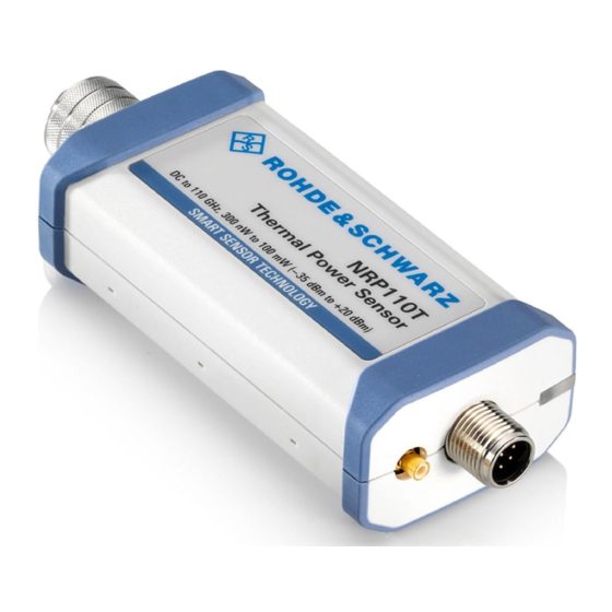
® Power Sensor Tour R&S NRPxxT(N) RF Connector 4 Power Sensor Tour This chapter provides an overview of the available connectors and LEDs of the power sensor. Figure 4-1, the USB power sensor is shown on the left, the LAN power sensor is shown on the right. -
Page 26: Trigger I/O Connector
® Power Sensor Tour R&S NRPxxT(N) Status LED Table 4-1: R&S NRPxxT(N) RF connector characteristics Power sensor Male connector Matching female con- Tightening torque nector R&S NRP18T 1.36 Nm (12'' lbs) R&S NRP18TN R&S NRP33T 3.50 mm R&S NRP33TN 3.50 mm/ 2.92 mm/ SMA R&S NRP40T 2.92 mm R&S NRP40TN... -
Page 27: Lan Poe Interface
® Power Sensor Tour R&S NRPxxT(N) LAN PoE Interface Indication State White Idle state. The sensor performs no measurement and is ready for use. Flashing white Firmware update is in progress Slow flashing white Sanitizing in progress Yellow Wait for trigger state Green Measuring state Turquoise blue... - Page 28 ® Power Sensor Tour R&S NRPxxT(N) LAN PoE Interface Power over Ethernet status LED Available only for LAN power sensor. The power status LED shows whether the sensor is correctly powered over PoE or not. Color State Green The sensor is powered over PoE. You can operate it using the Ethernet interface. No light No PoE power is present.
-
Page 29: Operating Concepts
® Operating Concepts R&S NRPxxT(N) R&S NRP Toolkit 5 Operating Concepts For operating the power sensor, you can choose from various possibilities: ● Chapter 5.2, "Browser-Based User Interface", on page 32 ● Chapter 5.3, "Remote Control", on page 34 ● Chapter 5.4, "R&S NRPV", on page 34... -
Page 30: R&S Nrp Toolkit For Windows
® Operating Concepts R&S NRPxxT(N) R&S NRP Toolkit Supported operating systems: ● Microsoft Windows versions – Microsoft Windows Vista 32/64-bit – Microsoft Windows 7 32/64-bit – Microsoft Windows 8/ 8.1 32/64-bit – Microsoft Windows 10 32/64-bit ● For information on other operating systems, see Chapter 5.1.1, "Versions and Downloads", on page 29. -
Page 31: Components Of The R&S Nrp Toolkit
® Operating Concepts R&S NRPxxT(N) R&S NRP Toolkit 3. Accept the license terms to continue with the installation. 4. Click "Next" and complete the installation process. 5.1.3.1 Components of the R&S NRP Toolkit Access: "Start" > "NRP-Toolkit" The following tools are part of the R&S NRP Toolkit for Windows. Configure Network Sensor Useful if you have troubles establishing a LAN connection with an R&S NRP LAN power sensor. -
Page 32: Browser-Based User Interface
® Operating Concepts R&S NRPxxT(N) Browser-Based User Interface NRP Version Display Displays version information of all installed, power measurement-relevant software packages. R&S NRP‑Z Uncertainty Calculator Determines the expanded measurement uncertainty. The tool comes with a manual (PDF) that is also available in the "Start" menu. S-Parameter Update Multi Helps loading an S-parameter table into the power sensor. - Page 33 ® Operating Concepts R&S NRPxxT(N) Browser-Based User Interface Setup HOST INTERFACE TRIG2 3 V or 5 V logic OUT: min. 2 V into 50 Ω max. 5.3 V SMART SENSOR TECHNOLOGY Figure 5-1: Setup with the web user interface = Signal source = LAN power sensor = RJ-45 Ethernet connector 4, 6 = RJ-45 Ethernet cable...
-
Page 34: Remote Control
® Operating Concepts R&S NRPxxT(N) R&S NRPV The main dialog of the web user interface opens. 4. Select the "Continuous Average" tab and perform any necessary changes. 5. Press "Measurement > ON" to start the measurement. For a detailed description of the web user interface, refer to Chapter 6, "Browser- Based User Interface",... - Page 35 ® Operating Concepts R&S NRPxxT(N) R&S NRPV – R&S NRP Toolkit V 4.20 or higher – R&S NRPV version 3.2 or higher (refer to the operating manual of the R&S NRPV for a description of the installation process) Setup 3-Path Diode Power Sensor MHz to GHz, 100 pW to 200 mW (−70 dBm to +23 dBm) SMART SENSOR TECHNOLOGY Figure 5-2: Setup with an R&S NRPV...
-
Page 36: R&S Power Viewer
® Operating Concepts R&S NRPxxT(N) R&S Power Viewer 4. Switch on the test signal of the signal source. 5. To start a continuous measurement, select "Measure > Continuous". The "Continuous" measurement window appears. It shows the measurement results numerically, and the control panel for accessing further dialogs with param- eters for measurement, evaluation and display. - Page 37 ® Operating Concepts R&S NRPxxT(N) R&S Power Viewer – R&S Power Viewer version 9.2 or higher (refer to the operating manual of the R&S Power Viewer for a description of the installation process) If you want to use an android device like a tablet or a smartphone, use the R&S Power Viewer Mobile.
-
Page 38: R&S Power Viewer Mobile
® Operating Concepts R&S NRPxxT(N) R&S Power Viewer Mobile b) Select "Sensor > Zero (Signal off) ". 4. Switch on the test signal of the signal source. 5. For a continuous average measurement, select "Measurement" > "Continuous". The "Continuous" measurement window appears. It shows the measurement results numerically and some parameters that can be configured. -
Page 39: R&S Nrx
® Operating Concepts R&S NRPxxT(N) R&S NRX You can download the R&S Power Viewer Mobile free of charge from the Google Play Store. ® The 1MA215 "Using R&S NRP Series Power Sensors with Android Handheld Devi- ces" application note gives a detailed description on installation and features of the R&S Power Viewer Mobile. -
Page 40: R&S Nrp2
® Operating Concepts R&S NRPxxT(N) R&S NRP2 Starting a measurement 1. Preset the R&S NRX and the connected R&S power sensors. a) Press the [Preset] key. b) Tap "Preset". All parameters are set to their defaults. 2. Note: Turn off all measurement signals before zeroing. An active measurement signal during zeroing causes an error. - Page 41 ® Operating Concepts R&S NRPxxT(N) R&S NRP2 Setup 3-Path Diode Power Sensor MHz to GHz, 100 pW to 200 mW (−70 dBm to +23 dBm) SMART SENSOR TECHNOLOGY Figure 5-5: Setup with an R&S NRP2 base unit 1 = Signal source 2 = R&S NRPxxT(N) power sensor 3 = Host interface connector 4 = R&S NRP‑ZK6 cable...
- Page 42 ® Operating Concepts R&S NRPxxT(N) R&S NRP2 b) Press the [ZERO] hardkey of the R&S NRP2. The "Zero" dialog box is displayed. c) Press the [ZERO] hardkey again to perform zeroing of all connected sensor channels ("Zero (All)") or press the appropriate softkey to select a specific sen- sor for zeroing.
-
Page 43: Browser-Based User Interface
® Browser-Based User Interface R&S NRPxxT(N) Main Dialog of the Web User Interface 6 Browser-Based User Interface The web user interface is an alternative way to operate an R&S NRPxxTN LAN power sensor. This chapter provides a description of the parameters used for setting a power mea- surement with the web user interface. -
Page 44: Setting The Unit
® Browser-Based User Interface R&S NRPxxT(N) Setting the Unit Result pane Displays the measurement result for the selected measurement mode. It can display only a value or a graph, depending on the selected measurement mode. 6.2 Setting the Unit You can set the unit for the different parameters by typing the corresponding letter after the entered value. -
Page 45: Common Settings
® Browser-Based User Interface R&S NRPxxT(N) Common Settings dBm or dBµV. To change the unit, you must specify the desired value together with the full new unit once. Example: To change the representation of a "Trigger Level" of 100µW into dBm, enter -10dbm in the "Trigger Level"... -
Page 46: Measurement Modes
® Browser-Based User Interface R&S NRPxxT(N) Measurement Modes <Value> ← Offset Adds a fixed level offset in dB to account for external losses. Remote command: [SENSe<Sensor>:]CORRection:OFFSet S-Parameter Selects the mode used for the S-parameters. S-parameters are used to compensate for a component (attenuator, directional coupler) connected ahead of the sensor. See also Chapter 9.8.3.3, "S-Parameter Correction",... -
Page 47: Continuous Average Mode
® Browser-Based User Interface R&S NRPxxT(N) Settings 6.4.1 Continuous Average Mode Describes the parameters of the continuous average measurement. Further information: ● Chapter 9.7.1, "Continuous Average Measurement", on page 85 Detailed description of the continuous average mode and its remote commands Access: main dialog of the web user interface >... -
Page 48: Sensor Settings
® Browser-Based User Interface R&S NRPxxT(N) Settings ● Sensor Settings.......................48 ● Averaging Settings....................49 ● Trigger Settings.......................50 ● System Settings...................... 52 6.5.1 Sensor Settings Describes the parameters for optimizing the measurement results for specific measure- ment requirements. Further information: ● Chapter 9.8.3, "Configuring Corrections", on page 92... -
Page 49: Averaging Settings
® Browser-Based User Interface R&S NRPxxT(N) Settings Remote command: [SENSe<Sensor>:]SGAMma:PHASe Zero Calibration Performs zeroing using the signal at the sensor input. See Chapter 9.9, "Calibrating, Zeroing", on page 108. Note: Turn off all test signals before zeroing. An active test signal during zeroing causes an error. -
Page 50: Trigger Settings
® Browser-Based User Interface R&S NRPxxT(N) Settings "Repeating" Specifies that a measurement result is not output until the entire mea- surement has been completed. This means that the number of mea- surement cycle repetitions is equal to the set averaging factor. If the averaging factor is large, the measurement time can be very long. - Page 51 ® Browser-Based User Interface R&S NRPxxT(N) Settings <Slope> ← Trigger Source Sets the polarity of the active slope of the trigger signal that is externally or internally applied. The rising edge of the trigger signal is used for triggering. "Positive" "Negative"...
-
Page 52: System Settings
® Browser-Based User Interface R&S NRPxxT(N) Settings 6.5.4 System Settings Describes the parameters of the general network environment and specific identifica- tion parameters of the power sensor in the network. Further information: ● Chapter 9.11, "Configuring the System", on page 111 Access: main dialog of the web user interface >... - Page 53 ® Browser-Based User Interface R&S NRPxxT(N) Settings Remote command: SYSTem:COMMunicate:NETWork:IPADdress:GATeway DHCP Selects the mode for assigning the IP address. "Auto" Assigns the IP address automatically, provided the network supports DHCP (dynamic host configuration protocol). "Static" Enables assigning the IP address manually. Remote command: SYSTem:COMMunicate:NETWork:IPADdress:MODE Selftest...
- Page 54 ® Browser-Based User Interface R&S NRPxxT(N) Settings Apply Network Settings After you have made the required network settings changes, apply them to the power sensor by clicking "Apply Network Settings". Firmware Update Opens a dialog to start the firmware update. For further information, see Chapter 7.2.2, "Using the Web User Interface",...
-
Page 55: Firmware Update
® Firmware Update R&S NRPxxT(N) Updating the Firmware 7 Firmware Update ● Hardware and Software Requirements..............55 ● Updating the Firmware....................55 7.1 Hardware and Software Requirements For performing a firmware update, the system requirements are as follows: ● Connectors and cables for establishing a connection to the computer Chapter 3.6.1, "Computer", on page 15. -
Page 56: Using The Firmware Update For Nrp Family Program
® Firmware Update R&S NRPxxT(N) Updating the Firmware 7.2.1 Using the Firmware Update for NRP Family Program Firmware Update for NRP Family is part of the R&S NRP Toolkit. See also Chap- ter 5.1, "R&S NRP Toolkit", on page 29. Checking the prerequisites 1. - Page 57 ® Firmware Update R&S NRPxxT(N) Updating the Firmware Note: The "Hostname or IP Address" field is not used during this procedure. There- fore, leave it empty. 6. Under "Firmware", enter the full path and filename of the update file, or press the browse button next to the field.
-
Page 58: Using The Web User Interface
® Firmware Update R&S NRPxxT(N) Updating the Firmware 7.2.2 Using the Web User Interface 1. Connect the power sensor to the computer as described in Chapter 3.6.1, "Com- puter", on page 15. 2. Open the web user interface as described in Chapter 5.2, "Browser-Based User Interface", on page 32. - Page 59 ® Firmware Update R&S NRPxxT(N) Updating the Firmware Example: You want to update your R&S NRP18TN with the nrp18tn_FW_15.02.12.01.rsu file. This file has a size of 10242884 bytes. To send the file to the sensor for updating the firmware, your application has to assem- ble a memory block containing: SYST:FWUP <block_data>...
-
Page 60: Replacing An R&S Nrp-Zxx With An R&Snrpxxt(N)
® Replacing an R&S NRP‑Zxx with an R&S NRPxxT(N) R&S NRPxxT(N) Prerequisites 8 Replacing an R&S NRP‑Zxx with an R&S NRPxxT(N) The R&S NRPxxT(N) power sensors are compatible with the R&S NRP‑Zxx series of power sensors. R&S NRPxx power sensor Replaces R&S NRP‑Zxx power sensor R&S NRP18T / R&S NRP18TN - USB connected R&S NRP-Z51... - Page 61 ® Replacing an R&S NRP‑Zxx with an R&S NRPxxT(N) R&S NRPxxT(N) Prerequisites The new version of the R&S NRP Toolkit is compatible with both the R&S NRP‑Zxx and the R&S NRPxxT(N) so that its installation does not affect the usage of the R&S NRP‑Zxx power sensors.
-
Page 62: Remote Control Commands
® Remote Control Commands R&S NRPxxT(N) Notations 9 Remote Control Commands In the following, all commands implemented in the sensor are listed according to the command system and then described in detail. Mostly, the notation used complies with SCPI specifications. 9.1 Conventions Used in SCPI Command Descriptions Note the following conventions used in the remote command descriptions: ●... - Page 63 ® Remote Control Commands R&S NRPxxT(N) Notations Numeric suffixes <n> If a command can be applied to multiple instances of an object, e.g. specific sensors, the required instances can be specified by a suffix added to the command. Numeric suffixes are indicated by angular brackets (<1...4>, <n>, <I>) and are replaced by a single value in the command.
-
Page 64: Common Commands
® Remote Control Commands R&S NRPxxT(N) Common Commands Special characters | and { } A vertical bar in parameter definitions indicates alternative possibilities in the sense of "or". The effect of the command differs, depending on which parameter is used. Example: Definition: INITiate:CONTinuous ON | OFF Command INITiate:CONTinuous ON starts the measurements... -
Page 65: Idn
® Remote Control Commands R&S NRPxxT(N) Common Commands *ESE <register> Event status enable Sets the event status enable register to the specified value. The query returns the con- tents of the event status enable register in decimal form. Parameters: <register> Range: 0 to 255 *RST:... -
Page 66: Opt
® Remote Control Commands R&S NRPxxT(N) Common Commands *OPT? Option identification Returns a comma-separated list of installed options. Usage: Query only *PRE <register> Parallel poll register enable Sets the parallel poll enable register to the specified value or queries the current value. Parameters: <register>... -
Page 67: Stb
® Remote Control Commands R&S NRPxxT(N) Common Commands *SRE <register> Service request enable Sets the service request enable register to the specified value. This command deter- mines under which conditions a service request is triggered. Parameters: <register> Range: 0 to 255 *RST: *STB? Status byte... -
Page 68: Preparing For The Measurement
® Remote Control Commands R&S NRPxxT(N) Preparing for the Measurement 9.4 Preparing for the Measurement Before starting a measurement, you need to do the following: ● Selecting the Reference Source................68 ● Selecting a Measurement Mode................68 9.4.1 Selecting the Reference Source The ROSCillator subsystem contains commands for configuring the reference source. -
Page 69: Controlling The Measurement
® Remote Control Commands R&S NRPxxT(N) Controlling the Measurement Parameters: <function> "POWer:AVG" Continuous average mode After a trigger event, the power is integrated over a time interval (averaging) set using: [SENSe<Sensor>:][POWer:][AVG:]APERture. *RST: "POWer:AVG" 9.5 Controlling the Measurement The power sensor offers a bunch of possibilities to control the measurement: ●... -
Page 70: Triggering
® Remote Control Commands R&S NRPxxT(N) Controlling the Measurement Use the command only after the continuous measurement mode has been switched off (INITiate:CONTinuous OFF). See also Chapter 9.5, "Controlling the Measurement", on page 69. Example: Chapter 10.2, "Performing a Buffered Continuous Average Measurement", on page 128. -
Page 71: Waiting For A Trigger Event
® Remote Control Commands R&S NRPxxT(N) Controlling the Measurement ● Waiting for trigger The power sensor waits for a trigger event that is defined by the trigger source. When the trigger event occurs, the power sensor enters the measuring state. ●... -
Page 72: Dropout Time
® Remote Control Commands R&S NRPxxT(N) Controlling the Measurement 9.5.2.4 Dropout Time The dropout time is useful when dealing with signals with several active slots, for example GSM signals, see Figure 9-1. When measuring in sync with the signal, a trig- ger event is to be produced at A, but not at B or C. -
Page 73: Controlling The Measurement Results
® Remote Control Commands R&S NRPxxT(N) Controlling the Measurement 9.5.3 Controlling the Measurement Results The R&S NRPxxT(N) can cope with the wide range of measurement scenarios with the help of the so-called "termination control". Depending on how fast your measurement results change, you can define, how the measurement results are output. -
Page 74: Continuous Average Mode
® Remote Control Commands R&S NRPxxT(N) Controlling the Measurement 9.5.4.1 Continuous Average Mode General settings for these examples: ● INITiate:CONTinuous ● [SENSe<Sensor>:]AVERage:COUNt ● [SENSe<Sensor>:]AVERage:COUNt:AUTO Example: Repeating termination control Further settings for this example: ● [SENSe<Sensor>:]AVERage:TCONtrol REPeat The measurement is started by the trigger event. Due to the chopper phases, one measurement lasts twice the defined aperture time. - Page 75 ® Remote Control Commands R&S NRPxxT(N) Controlling the Measurement Example: Moving termination control Further settings for this example: ● [SENSe<Sensor>:]AVERage:TCONtrol MOVing ● TRIGger:COUNt Every measurement is started by a trigger event. Due to the chopper phases, one measurement lasts twice the defined aperture time. During each measurement, the trigger synchronization is high (TRIGger:SYNC:STATe ON).
-
Page 76: Configuring The Trigger
® Remote Control Commands R&S NRPxxT(N) Controlling the Measurement Example: Average count = 1 [SENSe<Sensor>:]AVERage:COUNt For average count 1, the setting of the termination control has no impact. In both cases, the measurement runs for the duration of one aperture time. Then, settled data is available, and the power sensor returns to the idle state. -
Page 77: Trigger:atrigger:executed
® Remote Control Commands R&S NRPxxT(N) Controlling the Measurement Sets the delay between the artificial trigger event and the beginning of the actual mea- surement Parameters: <delay> Range: 0.1 to 5.0 *RST: Default unit: Seconds TRIGger:ATRigger:EXECuted? Queries the number of measurements that were triggered automatically since was set to ON. -
Page 78: Trigger:delay
® Remote Control Commands R&S NRPxxT(N) Controlling the Measurement TRIGger:DELay <delay> Sets the delay between the trigger event and the beginning of the actual measurement (integration). Note: In continuous average mode, a negative trigger delay is not supported. Parameters: <delay> Range: -5.0 to 10.0 *RST:... -
Page 79: Trigger:holdoff
® Remote Control Commands R&S NRPxxT(N) Controlling the Measurement HIGH ~10 kΩ 50 Ω *RST: HIGH TRIGger:HOLDoff <holdoff> Sets the hold-off time, seeChapter 9.5.2.5, "Hold-Off Time", on page 72 . Parameters: <holdoff> Range: 0.00 to 10.00 *RST: 0.00 Default unit: Seconds Manual operation: "Holdoff"... -
Page 80: Trigger:level:unit
® Remote Control Commands R&S NRPxxT(N) Controlling the Measurement If you enter a value without unit, the unit is defined by TRIGger:LEVel:UNIT. If an S-parameter device is active and/or if a mounted component with a global offset in front of the sensor is considered, the currently effective trigger threshold and a trig- ger threshold to be input are referenced to the appropriately shifted sensor data. -
Page 81: Trigger:sender:state
® Remote Control Commands R&S NRPxxT(N) Controlling the Measurement TRIGger:SENDer:STATe <state> Enables or disables the trigger sender mode of the sensor. In this state, the power sen- sor can output a digital trigger signal in sync with its own trigger event. If enabled, select the output port for the trigger signal using TRIGger:SENDer:PORT. -
Page 82: Configuring And Retrieving Results
® Remote Control Commands R&S NRPxxT(N) Configuring and Retrieving Results Parameters: <sync_port> EXT1 | EXTernal1 | EXT2 | EXTernal2 *RST: EXT1 TRIGger:SYNC:STATe <state> Usually used in combination with TRIGger:SENDer:STATe If enabled, blocks the external trigger bus as long as the sensor remains in the mea- surement state. - Page 83 ® Remote Control Commands R&S NRPxxT(N) Configuring and Retrieving Results ......................83 FORMat:BORDer ......................83 FORMat:SREGister ....................... 83 FORMat[:DATA] FORMat:BORDer <border> Selects the order of bytes in 32-bit or 64-bit binary data. Parameters: <border> NORMal | SWAPped NORMal The 1st byte is the least significant byte, the 4th/8th byte the most significant byte.
-
Page 84: Retrieving Results
® Remote Control Commands R&S NRPxxT(N) Configuring the Measurement Modes 32 | 64 32-bit or 64-bit If you omit the length, the R&S NRPxxT(N) sets the last used length. Example for REAL,32 format: #6768000..<binary float values>..Example for REAL,64 format: #71536000..<binary float values>.. -
Page 85: Continuous Average Measurement
® Remote Control Commands R&S NRPxxT(N) Configuring the Measurement Modes Further information: ● Chapter 9.8, "Configuring Basic Measurement Parameters", on page 88 ● Chapter 9.5, "Controlling the Measurement", on page 69 Contents: ● Continuous Average Measurement.................85 9.7.1 Continuous Average Measurement The continuous average mode measures the signal average power asynchronously within definable time intervals (sampling windows). - Page 86 ® Remote Control Commands R&S NRPxxT(N) Configuring the Measurement Modes 100 μs is the time for switching the chopper phase. Using ON, you can accelerate the mea- [SENSe<Sensor>:][POWer:][AVG:]FAST surement as follows: ● Chopper is disabled. ● Average count is set to 1, no matter which average count you have set. Thus, the overall measurement time is only defined by the aperture time, and the mea- surement time for a fast measurement is calculated as follows: MT = APER...
- Page 87 ® Remote Control Commands R&S NRPxxT(N) Configuring the Measurement Modes [SENSe<Sensor>:][POWer:][AVG:]BUFFer:DATA? Queries the results of the continuous average result buffer and returns them even if the buffer is not full. In contrast, returns a result only if FETCh<Sensor>[:SCALar][:POWer][:AVG]? the buffer is full. Usage: Query only [SENSe<Sensor>:][POWer:][AVG:]BUFFer:SIZE <count>...
-
Page 88: Configuring Basic Measurement Parameters
® Remote Control Commands R&S NRPxxT(N) Configuring Basic Measurement Parameters Example: FAST ON [SENSe<Sensor>:][POWer:][AVG:]SMOothing:STATe <state> Enables or disables the smoothing filter, a steep-edge digital lowpass filter. If you can- not adjust the aperture time exactly to the modulation period, the filter reduces result fluctuations caused by modulation. - Page 89 ® Remote Control Commands R&S NRPxxT(N) Configuring Basic Measurement Parameters Parameters: <count> Range: 1 to 65536 *RST: Example: AVER:COUN 1 Manual operation: "<Value>" on page 46 [SENSe<Sensor>:]AVERage:COUNt:AUTO <state> Sets the mode for determining the average count. Parameters: <state> Auto averaging: the averaging factor is continuously determined and set depending on the level of power and other parameters.
- Page 90 ® Remote Control Commands R&S NRPxxT(N) Configuring Basic Measurement Parameters The noise component is defined as the magnitude of the level variation in dB caused by the inherent noise of the sensor (two standard deviations). The query returns the relative noise component in the measured value. Parameters: <nsr>...
- Page 91 ® Remote Control Commands R&S NRPxxT(N) Configuring Basic Measurement Parameters [SENSe<Sensor>:]AVERage:COUNt:AUTO:TYPE <type> Sets the automatic averaging filter mode. Parameters: <type> RESolution | NSRatio RESolution The usual mode for the power sensors. NSRatio Predefines the compliance to an exactly defined noise compo- nent.
-
Page 92: Setting The Frequency
® Remote Control Commands R&S NRPxxT(N) Configuring Basic Measurement Parameters 9.8.2 Setting the Frequency The frequency of the signal to be measured is not automatically determined. For ach- ieving better accuracy, the carrier frequency of the applied signal must be set. [SENSe<Sensor>:]FREQuency <frequency>... -
Page 93: Offset Corrections
® Remote Control Commands R&S NRPxxT(N) Configuring Basic Measurement Parameters Parameters: <duty_cycle> Range: 0.001 to 100.00 *RST: 1.00 Default unit: Percent Manual operation: "Duty Cycle" on page 47 [SENSe<Sensor>:]CORRection:DCYCle:STATe <state> Enables or disables the duty cycle correction for the measured value. Parameters: <state>... -
Page 94: S-Parameter Correction
® Remote Control Commands R&S NRPxxT(N) Configuring Basic Measurement Parameters Manual operation: "<State>" on page 45 9.8.3.3 S-Parameter Correction S-parameter correction compensates for the losses and reflections introduced by a component – such as an attenuator, directional coupler, or matching pad – that is attached to a power sensor. - Page 95 ® Remote Control Commands R&S NRPxxT(N) Configuring Basic Measurement Parameters 3-Path Diode Power Sensor MHz to GHz, 100 pW to 200 mW (−70 dBm to +23 dBm) SMART SENSOR TECHNOLOGY Figure 9-2: Operation with 2-port device between signal source and sensor input Configuring the S-Parameter Correction ..............
-
Page 96: S-Gamma Corrections
® Remote Control Commands R&S NRPxxT(N) Configuring Basic Measurement Parameters 9.8.3.4 S-Gamma Corrections Using the complex reflection coefficient, you can determine the power P delivered by the signal source with considerably greater accuracy. The coefficient of the signal source Γ is defined by its magnitude and phase: source ●... -
Page 97: I-Gamma Queries
® Remote Control Commands R&S NRPxxT(N) Configuring Basic Measurement Parameters [SENSe<Sensor>:]SGAMma:CORRection:STATe <state> Enables or disables the use of the complex reflection coefficient to correct the interac- tions of power sensor and signal source. Parameters: <state> *RST: Manual operation: "<State>" on page 48 [SENSe<Sensor>:]SGAMma:MAGNitude <magnitude>... -
Page 98: Using The S-Parameters Tool
® Remote Control Commands R&S NRPxxT(N) Configuring Basic Measurement Parameters Example: IGAM:MAGN? Query 1.739179E-02 Response Usage: Query only [SENSe<Sensor>:]IGAMma:PHASe? Queries the phase angle of the complex input reflection coefficient Γ . The result is provided in degrees. Range: -180 degrees to +180 degrees. Example: IGAM:PHAS? Query... -
Page 99: Menu Bar
® Remote Control Commands R&S NRPxxT(N) Configuring Basic Measurement Parameters User Interface of the S-Parameters Tool Figure 9-5: S-Parameters dialog Menu bar........................99 └ File........................99 └ Sensor......................100 └ Device......................100 └ Options......................100 └ User Data....................100 └ Remote....................100 └ Show Cal. -
Page 100: Sensor
® Remote Control Commands R&S NRPxxT(N) Configuring Basic Measurement Parameters Sensor ← Menu bar Provides options for loading and saving calibration data directly from or to the sensor, see: ● "To load a calibration data set from a power sensor" on page 102 ●... -
Page 101: Global Flags
® Remote Control Commands R&S NRPxxT(N) Configuring Basic Measurement Parameters Figure 9-6: Example Global Flags Groups the settings for the power sensor behavior regarding S-parameter corrections. S-Parameter Correction ON by Default ← Global Flags If this option is enabled, the S-parameter correction is activated automatically when the sensor is started. -
Page 102: Use Flags In Factory Cal. Data Set
® Remote Control Commands R&S NRPxxT(N) Configuring Basic Measurement Parameters Use Flags in Factory Cal. Data Set ← Global Flags Available if the power sensor supports two different calibration data sets: ● Factory calibration data set containing all factory calibration data. ●... - Page 103 ® Remote Control Commands R&S NRPxxT(N) Configuring Basic Measurement Parameters The "Upload Calibration Data" dialog opens. It shows a list of the available sen- sors. 3. If you cannot find your power sensor in the list, for example because of reconnect- ing the power sensor, you can reload the list by clicking "Rebuild List".
- Page 104 ® Remote Control Commands R&S NRPxxT(N) Configuring Basic Measurement Parameters 6. Create a backup of the calibration data set before making any changes. Select "File" > "Save Calibration Data". A dialog opens where you can select the location to save the calibration data. To change the S-parameter data 1.
- Page 105 ® Remote Control Commands R&S NRPxxT(N) Configuring Basic Measurement Parameters 4. If needed, load uncertainty data. See "To load an uncertainty parameter file" on page 105. 5. Check the entries in the " S-Parameter Device Mnemonic", "Lower Power Limit/W" and "Upper Power Limit/W" fields and change them, if necessary. For example, the lower and upper power limits are deduced from the power limits of the sensor itself and the minimum attenuation of the S-parameter device.
- Page 106 ® Remote Control Commands R&S NRPxxT(N) Configuring Basic Measurement Parameters To save the calibration data to the sensor 1. Select "Sensor" > "Save Calibration Data". The "Download Calibration Data" dialog opens. 2. Confirm that the correct power sensor is selected by clicking "Download". After a successful transfer of the data to the power sensor, a confirmation message is displayed.
- Page 107 ® Remote Control Commands R&S NRPxxT(N) Configuring Basic Measurement Parameters ● Option line The option line has the format #[<frequency unit>][<parameter>][<format>][<R n>], where: – Identifies the option line. – <frequency unit> Possible values are Hz, kHz, MHz or GHz. If a frequency unit is not specified, GHz is implicitly assumed.
-
Page 108: Calibrating, Zeroing
® Remote Control Commands R&S NRPxxT(N) Calibrating, Zeroing – <parameter> U must be specified for uncertainty data files. If a parameter is not specified, S is implicitly assumed and as a result an error message is triggered. – <format> This value is ignored in uncertainty measurement files. The entry is therefore irrelevant. - Page 109 ® Remote Control Commands R&S NRPxxT(N) Calibrating, Zeroing ..................109 CALibration:TEST:DEViation? ..................110 CALibration:TEST:REFerence? ....................110 CALibration:USER:DATA .................. 110 CALibration:USER:DATA:LENGth? ................110 CALibration<Channel>:ZERO:AUTO CALibration:DATA <caldata> Writes a binary calibration data set in the memory of the sensor. Parameters: <caldata> <block_data> CALibration:DATA:LENGth? Queries the length in bytes of the calibration data set currently stored in the flash mem- ory.
- Page 110 ® Remote Control Commands R&S NRPxxT(N) Calibrating, Zeroing CALibration:TEST:REFerence? The thermal power sensors are equipped with an additional test heater. Queries the reference value of the power difference in W when measuring with the external heater enabled and disabled. The reference value is determined during the calibration process and stored in the calibration data set.
-
Page 111: Testing
® Remote Control Commands R&S NRPxxT(N) Configuring the System Suffix: <Channel> 1...4 Measurement channel if more than one channel is available. Parameters: <state> ONCE Only valid parameter for this command. Return value if no calibration is in progress. *RST: Example: *CLS CAL1:ZERO:AUTO ONCE Performs zeroing. - Page 112 ® Remote Control Commands R&S NRPxxT(N) Configuring the System The SYSTem:COMMunicate:NETWork:... commands are only available for the R&S NRP LAN power sensors. Remote commands: ..............113 SYSTem:COMMunicate:NETWork:RESTart ................. 113 SYSTem:COMMunicate:NETWork:RESet ..............113 SYSTem:COMMunicate:NETWork:STATus? ............113 SYSTem:COMMunicate:NETWork[:COMMon]:DOMain ..........113 SYSTem:COMMunicate:NETWork[:COMMon]:HOSTname ..............114 SYSTem:COMMunicate:NETWork:IPADdress .............114 SYSTem:COMMunicate:NETWork:IPADdress:GATeway ............115...
-
Page 113: System:communicate:network:restart
® Remote Control Commands R&S NRPxxT(N) Configuring the System SYSTem:COMMunicate:NETWork:RESTart Effective only for the R&S NRP LAN power sensors. Restarts the network connection to the DUT, that means terminates the connection and sets it up again. Example: SYST:COMM:NETW:REST Usage: Event SYSTem:COMMunicate:NETWork:RESet Effective only for the R&S NRP LAN power sensors. -
Page 114: System:communicate:network:ipaddress
® Remote Control Commands R&S NRPxxT(N) Configuring the System In a LAN that uses a DNS server (domain name system server), you can access each connected instrument using a unique hostname instead of its IP address. The DNS server translates the hostname to the IP address. Using a hostname is especially use- ful if a DHCP server is used, as a new IP address can be assigned each time the instrument is restarted. -
Page 115: System:communicate:network:ipaddress:info
® Remote Control Commands R&S NRPxxT(N) Configuring the System Manual operation: "Gateway" on page 52 SYSTem:COMMunicate:NETWork:IPADdress:INFO? Effective only for the R&S NRP LAN power sensors. Queries the network status information. Usage: Query only SYSTem:COMMunicate:NETWork:IPADdress:MODE <mode> Effective only for the R&S NRP LAN power sensors. Sets whether the IP address is assigned automatically or manually. -
Page 116: System:error:all
® Remote Control Commands R&S NRPxxT(N) Configuring the System Suffix: <Channel> 1...4 Measurement channel if more than one channel is available. Usage: Query only SYSTem:ERRor:ALL? Queries all unread entries in the SCPI communication error queue and removes them from the queue. Returns a comma-separated list of error numbers and a short error description in the first-in first-out order. -
Page 117: System:error:count
® Remote Control Commands R&S NRPxxT(N) Configuring the System SYSTem:ERRor:COUNt? Queries the number of entries in the SCPI communication error queue. Example: SYST:ERR:COUN? Query Response: One error has occurred since the error queue was last read out. Usage: Query only SYSTem:ERRor[:NEXT]? Queries the SCPI communication error queue for the oldest entry and removes it from the queue. -
Page 118: System:fwupdate:status
® Remote Control Commands R&S NRPxxT(N) Configuring the System SYSTem:FWUPdate:STATus? Reads the result of the firmware update performed using SYSTem:FWUPdate on page 117. While a firmware update is in progress, the LED of the sensor flashes in bright white color. When the firmware update is completed, you can read the result. The result of the query is a readable string. - Page 119 ® Remote Control Commands R&S NRPxxT(N) Configuring the System If you want to query specific information, add a query parameter. Query parameters: <item> "<string>" with the following values: Manufacturer Type Stock Number Serial SW Build MAC Address Hostname IP Address Domain Subnetmask Gateway...
-
Page 120: System:initialize
® Remote Control Commands R&S NRPxxT(N) Configuring the System Usage: Query only Manual operation: "Sensor Information" on page 49 SYSTem:INITialize Sets the sensor to the standard state, i.e. the default settings for all test parameters are loaded in the same way as with *RST. The sensor then outputs a complete list of all supported commands and parameters. -
Page 121: System:led:mode
® Remote Control Commands R&S NRPxxT(N) Configuring the System SYSTem:LED:MODE <mode> Sets whether the color of the system status LED is controlled by the sensor firmware or by the user settings. For more information, see SYSTem:LED:COLor. Parameters: <mode> USER | SENSor *RST: SENSor SYSTem:MINPower? -
Page 122: System:reboot
® Remote Control Commands R&S NRPxxT(N) Configuring the System SYSTem:REBoot Reboots the sensor. Usage: Event SYSTem:RESTart Restarts the firmware of the R&S NRPxxT(N). Usage: Event SYSTem:RUTime <update_time> Effective only in the NRP legacy mode. Sets the result update time. That is the maximum rate in which the power sensor can output measurement results. -
Page 123: System:serror:list[:Next]
® Remote Control Commands R&S NRPxxT(N) Configuring the System SYSTem:SERRor:LIST[:NEXT]? Queries the list of static error changes for the oldest entry and removes it from the queue. Returns an error number and a short description of the error. Example: SYST:SERR:LIST? Query 0,"reported at uptime:2942;... -
Page 124: Using The Status Register
® Remote Control Commands R&S NRPxxT(N) Using the Status Register The sensor name that you specify here is independent from the hostname of the sen- sor. However, if the sensor name is not specified, it defaults to the hostname. Example: SYST:NAME "InputModule-X5"... -
Page 125: General Status Register Commands
® Remote Control Commands R&S NRPxxT(N) Using the Status Register 9.12.1 General Status Register Commands ......................125 STATus:PRESet ....................125 STATus:QUEue[:NEXT]? STATus:PRESet Resets the edge detectors and ENABle parts of all registers to a defined value. Usage: Event STATus:QUEue[:NEXT]? Queries the most recent error queue entry and deletes it. Positive error numbers indicate sensor specific errors. -
Page 126: Controlling The Enable Part
® Remote Control Commands R&S NRPxxT(N) Using the Status Register STATus:OPERation:LLFail[:SUMMary][:EVENt]? STATus:OPERation:MEASuring[:SUMMary][:EVENt]? STATus:OPERation:SENSe[:SUMMary][:EVENt]? STATus:OPERation:TRIGger[:SUMMary][:EVENt]? STATus:OPERation:ULFail[:SUMMary][:EVENt]? STATus:QUEStionable:CALibration[:SUMMary][:EVENt]? STATus:QUEStionable[:EVENt]? STATus:QUEStionable:POWer[:SUMMary][:EVENt]? STATus:QUEStionable:WINDow[:SUMMary][:EVENt]? Usage: Query only 9.12.4 Controlling the ENABle Part Further information: ● Chapter 11.3.2, "Structure of a SCPI Status Register", on page 143 STATus:DEVice:ENABle <value>... -
Page 127: Controlling The Positive Transition Part
® Remote Control Commands R&S NRPxxT(N) Using the Status Register STATus:QUEStionable:POWer:NTRansition <value> STATus:QUEStionable:WINDow:NTRansition <value> Parameters: <value> *RST: 9.12.6 Controlling the Positive Transition Part Further information: ● Chapter 11.3.2, "Structure of a SCPI Status Register", on page 143 STATus:DEVice:PTRansition <value> STATus:OPERation:CALibrating:PTRansition <value> STATus:OPERation:PTRansition <value>... -
Page 128: Performing Measurement Tasks - Programming Examples
® Performing Measurement Tasks - Programming Examples R&S NRPxxT(N) Performing a Buffered Continuous Average Measurement 10 Performing Measurement Tasks - Program- ming Examples If you install the optional software development kit (SDK) of the R&S NRP Toolkit, pro- gramming examples are provided. See Chapter 5.1, "R&S NRP Toolkit", on page 29. - Page 129 ® Performing Measurement Tasks - Programming Examples R&S NRPxxT(N) Performing a Buffered Continuous Average Measurement // Auto Averaging OFF and set Average Count = 4 SENSOR.write( "SENS:AVER:COUN:AUTO OFF" ); SENSOR.write( "SENS:AVER:COUN 4" ); // Select the trigger source if ( bUseBUSTrigger ) // We want to use '*TRG' to trigger a single physical measurement SENSOR.write( "TRIG:SOUR BUS"...
- Page 130 ® Performing Measurement Tasks - Programming Examples R&S NRPxxT(N) Performing a Buffered Continuous Average Measurement // Trigger a single physical measurement; either by '*TRG' // command or by an externally supplied pulse on the SMB-type connector if ( bUseBUSTrigger ) SENSOR.write( "*TRG"...
-
Page 131: Remote Control Basics
® Remote Control Basics R&S NRPxxT(N) Remote Control Interfaces and Protocols 11 Remote Control Basics ● Remote Control Interfaces and Protocols............. 131 ● SCPI Command Structure..................135 ● Status Reporting System..................142 11.1 Remote Control Interfaces and Protocols For remote control, communication between the R&S NRPxxT(N) power sensors and the controlling host is established based on various interfaces and protocols. - Page 132 ® Remote Control Basics R&S NRPxxT(N) Remote Control Interfaces and Protocols VISA library, it supports service request, triggers and other operations that are com- monly found in GPIB devices. Besides USBTMC, the NRP legacy protocol is available to ensure the compatibility of the R&S NRPxxT(N) power sensors with the R&S NRP‑Z series of power sensors.
-
Page 133: Ethernet Interface
® Remote Control Basics R&S NRPxxT(N) Remote Control Interfaces and Protocols 11.1.2 Ethernet Interface The Ethernet interface of the R&S NRP LAN power sensors allows you to integrate them in a local area network (LAN). For remote control via a network, the computer and the power sensor must be connec- ted via the Ethernet interface to a common network with TCP/IP network protocol. -
Page 134: Protocol
® Remote Control Basics R&S NRPxxT(N) Remote Control Interfaces and Protocols For details of the VXI-11 protocol, refer to Chapter 11.1.2.2, "VXI-11 Protocol", on page 134 . Socket Communication TCPIP::<IP address or hostname>::port::SOCKET ● port determines the used port number ●... -
Page 135: Socket Communication
® Remote Control Basics R&S NRPxxT(N) SCPI Command Structure ● Compatible IEEE 488.2 support for Message Exchange Protocol, Device Clear, Serial Poll, Remote/Local, Trigger, and Service Request ● Uses a single IANA registered port (4880), which simplifies the configuration of fire- walls ●... -
Page 136: Syntax For Common Commands
® Remote Control Basics R&S NRPxxT(N) SCPI Command Structure 11.2.1 Syntax for Common Commands Common (=device-independent) commands consist of a header preceded by an aster- isk (*) and possibly one or more parameters. Examples: *RST RESET Resets the instrument. *ESE EVENT STATUS ENABLE Sets the bits of the event status enable registers. -
Page 137: Scpi Parameters
® Remote Control Basics R&S NRPxxT(N) SCPI Command Structure Optional mnemonics Some command systems permit certain mnemonics to be inserted into the header or omitted. These mnemonics are marked by square brackets in the description. The instrument must recognize the long command to comply with the SCPI standard. Some commands are considerably shortened by these optional mnemonics. - Page 138 ® Remote Control Basics R&S NRPxxT(N) SCPI Command Structure Numeric values Numeric values can be entered in any form, i.e. with sign, decimal point and exponent. Values exceeding the resolution of the instrument are rounded up or down. The man- tissa can comprise up to 255 characters, the exponent must lie inside the value range -32000 to 32000.
- Page 139 ® Remote Control Basics R&S NRPxxT(N) SCPI Command Structure Boolean parameters Boolean parameters represent two states. The "ON" state (logically true) is represen- ted by "ON" or a numeric value 1. The "OFF" state (logically untrue) is represented by "OFF" or the numeric value 0. The numeric values are provided as the response for a query.
-
Page 140: Overview Of Syntax Elements
® Remote Control Basics R&S NRPxxT(N) SCPI Command Structure Example: SYSTem:HELP:SYNTax:ALL? Response: #45168xxxxxxxx The ASCII character # introduces the data block. The next number indicates how many of the following digits describe the length of the data block. In the example, the 4 fol- lowing digits indicate the length to be 5168 bytes. -
Page 141: Responses To Queries
® Remote Control Basics R&S NRPxxT(N) SCPI Command Structure Several commands in a command line must be separated by a semicolon ";". If the next command belongs to a different command system, the semicolon is followed by a colon. If the successive commands belong to the same system, having one or several levels in common, the command line can be abbreviated. -
Page 142: Status Reporting System
® Remote Control Basics R&S NRPxxT(N) Status Reporting System Response: INT 11.3 Status Reporting System The status reporting system stores all information on the current operating state of the sensor, and on errors which have occurred. This information is stored in the status reg- isters and in the error queue. -
Page 143: Structure Of A Scpi Status Register
® Remote Control Basics R&S NRPxxT(N) Status Reporting System The highest level is formed by the status byte register (STB) and the associated ser- vice request enable (SRE) register. The status byte register (STB) receives its information from: ● Standard event status register (ESR) ●... -
Page 144: Status Byte (Stb) And Service Request Enable Register (Sre)
® Remote Control Basics R&S NRPxxT(N) Status Reporting System The Positive TRansition part acts as a transition filter. When a bit of the CONDition part is changed from 0 to 1, the associated PTR bit decides whether the EVENt bit is set to 1. - Page 145 ® Remote Control Basics R&S NRPxxT(N) Status Reporting System with the CONDition register of a SCPI defined register and is at the highest level of the SCPI hierarchy. Its special feature is that bit 6 acts as the summary bit of all other bits of the status byte register.
-
Page 146: Ist Flag And Parallel Poll Enable Register (Ppe)
® Remote Control Basics R&S NRPxxT(N) Status Reporting System Short description Bit is set if The sensor triggers a service request, which happens if one of the other bits of this register is set together with its enable bit Master status summary in the service request enable register (SRE). -
Page 147: Questionable Status Register
® Remote Control Basics R&S NRPxxT(N) Status Reporting System Querying the register: ● STATus:DEVice:CONDition? ● STATus:DEVice[:EVENt]? Querying the static errors: ● SYSTem:SERRor? Table 11-5: Used device status bits and their meaning Bit no. Short description Bit is set if Sum of SERR bits Sum/combination of SERR bits 1 to 4. -
Page 148: Questionable Power Status Register
® Remote Control Basics R&S NRPxxT(N) Status Reporting System Power summary Calibration summary POST failure Figure 11-4: Questionable status register Querying the register: ● STATus:QUEStionable:CONDition? ● STATus:QUEStionable[:EVENt]? Table 11-6: Used questionable status bits and their meaning Bit no. Short description Bit is set if Power summary Summary of... -
Page 149: Questionable Calibration Status Register
® Remote Control Basics R&S NRPxxT(N) Status Reporting System Sensor power Sensor please zero Figure 11-5: Questionable power status register Querying the register: ● STATus:QUEStionable:POWer:CONDition? ● STATus:QUEStionable:POWer[:SUMMary][:EVENt]? Table 11-7: Used questionable power status bits and their meaning Bit no. Short description Bit is set if Sensor power Measurement data of the power sensor is corrupt. -
Page 150: Standard Event Status And Enable Register (Esr, Ese)
® Remote Control Basics R&S NRPxxT(N) Status Reporting System Sensor calibration Figure 11-6: Questionable calibration status register Querying the register: ● STATus:QUEStionable:CALibration:CONDition? ● STATus:QUEStionable:CALibration[:SUMMary][:EVENt]? Table 11-8: Used questionable calibration status bits and their meaning Bit no. Short description Bit is set if Sensor calibration Zeroing of the power sensor was not successful. -
Page 151: Operation Status Register
® Remote Control Basics R&S NRPxxT(N) Status Reporting System Operation Complete Query Error Device-Dependent Error Execution Error Command Error User Request Power On Figure 11-7: Standard event status register (ESR) Table 11-9: Used standard event status bits and their meaning Bit no. -
Page 152: Operation Calibrating Status Register
® Remote Control Basics R&S NRPxxT(N) Status Reporting System Calibrating Measuring Triggering Sense summary Lower limit fail Upper limit fail Figure 11-8: Operation status register Querying the register: ● STATus:OPERation:CONDition? ● STATus:OPERation[:EVENt]? Table 11-10: Used operation status bits and their meaning Bit no. -
Page 153: Operation Measuring Status Register
® Remote Control Basics R&S NRPxxT(N) Status Reporting System Sensor calibrating Figure 11-9: Operation calibrating status register Querying the register: ● STATus:OPERation:CALibrating:CONDition? ● STATus:OPERation:CALibrating[:SUMMary][:EVENt]? Table 11-11: Used operation calibrating status bits and their meaning Bit no. Short description Bit is set if Sensor calibrating Sensor is being calibrated. -
Page 154: Operation Trigger Status Register
® Remote Control Basics R&S NRPxxT(N) Status Reporting System Sensor measuring Figure 11-10: Operation measuring status register Querying the register: ● STATus:OPERation:MEASuring:CONDition? ● STATus:OPERation:MEASuring[:SUMMary][:EVENt]? Table 11-12: Used operation measuring status bits and their meaning Bit no. Short description Bit is set if Sensor measuring Sensor is measuring. -
Page 155: Operation Sense Status Register
® Remote Control Basics R&S NRPxxT(N) Status Reporting System Sensor waiting for trigger Figure 11-11: Operation trigger status register Querying the register: ● STATus:OPERation:TRIGger:CONDition? ● STATus:OPERation:TRIGger[:SUMMary][:EVENt]? Table 11-13: Used operation trigger status bits and their meaning Bit no. Short description Bit is set if Sensor waiting for trigger Sensor is waiting for a trigger event. -
Page 156: Operation Lower Limit Fail Status Register
® Remote Control Basics R&S NRPxxT(N) Status Reporting System Sensor initializing Figure 11-12: Operation sense status register Querying the register: ● STATus:OPERation:SENSe:CONDition? ● STATus:OPERation:SENSe[:SUMMary][:EVENt]? Table 11-14: Used operation sense status bits and their meaning Bit no. Short description Bit is set if Sensor initializing Sensor is being initialized. -
Page 157: Operation Upper Limit Fail Status Register
® Remote Control Basics R&S NRPxxT(N) Status Reporting System Lower limit fail Figure 11-13: Operation lower limit fail status registers Querying the register: ● STATus:OPERation:LLFail:CONDition? ● STATus:OPERation:LLFail[:SUMMary][:EVENt]? Table 11-15: Used operation lower limit fail status bits and their meaning Bit no. Short description Bit is set if Lower limit fail... - Page 158 ® Remote Control Basics R&S NRPxxT(N) Status Reporting System Upper limit fail Figure 11-14: Operation upper limit fail status registers Querying the register: ● STATus:OPERation:ULFail:CONDition? ● STATus:OPERation:ULFail[:SUMMary][:EVENt]? Table 11-16: Used operation upper limit fail status bits and their meaning Bit no. Short description Bit is set if Upper limit fail...
-
Page 159: Troubleshooting
® Troubleshooting R&S NRPxxT(N) Performing a Selftest 12 Troubleshooting ● Displaying Status Information................159 ● Performing a Selftest.....................159 ● Problems during a Firmware Update..............160 ● Cannot Establish a LAN Connection..............160 ● Contacting Customer Support................160 12.1 Displaying Status Information Status information is available in several ways. Status LED of the R&S NRPxxT(N) The position of the status LED is indicated in Chapter 4, "Power Sensor... -
Page 160: Problems During A Firmware Update
® Troubleshooting R&S NRPxxT(N) Contacting Customer Support See also "Selftest" on page 53. 12.3 Problems during a Firmware Update The firmware update is described in Chapter 7, "Firmware Update", on page 55. Solutions for potential problems that can occur when using the Firmware Update for NRP Family, see "Troubleshooting"... - Page 161 ® Troubleshooting R&S NRPxxT(N) Contacting Customer Support Contact information Contact our customer support center at www.rohde-schwarz.com/support, or follow this QR code: Figure 12-1: QR code to the Rohde & Schwarz support page User Manual 1177.6023.02 ─ 08...
-
Page 162: List Of Commands
® List of commands R&S NRPxxT(N) List of commands [SENSe<Sensor>:][POWer:][AVG:]APERture....................86 [SENSe<Sensor>:][POWer:][AVG:]BUFFer:CLEar..................86 [SENSe<Sensor>:][POWer:][AVG:]BUFFer:COUNt?..................86 [SENSe<Sensor>:][POWer:][AVG:]BUFFer:DATA?..................87 [SENSe<Sensor>:][POWer:][AVG:]BUFFer:SIZE....................87 [SENSe<Sensor>:][POWer:][AVG:]BUFFer:STATe..................87 [SENSe<Sensor>:][POWer:][AVG:]FAST......................87 [SENSe<Sensor>:][POWer:][AVG:]SMOothing:STATe..................88 [SENSe<Sensor>:]AVERage:COUNt......................88 [SENSe<Sensor>:]AVERage:COUNt:AUTO....................89 [SENSe<Sensor>:]AVERage:COUNt:AUTO:MTIMe..................89 [SENSe<Sensor>:]AVERage:COUNt:AUTO:NSRatio..................89 [SENSe<Sensor>:]AVERage:COUNt:AUTO:RESolution................90 [SENSe<Sensor>:]AVERage:COUNt:AUTO:TYPE..................91 [SENSe<Sensor>:]AVERage:RESet........................90 [SENSe<Sensor>:]AVERage:TCONtrol......................91 [SENSe<Sensor>:]AVERage[:STATe]......................91 [SENSe<Sensor>:]CORRection:DCYCle......................92 [SENSe<Sensor>:]CORRection:DCYCle:STATe..................... 93 [SENSe<Sensor>:]CORRection:OFFSet......................93 [SENSe<Sensor>:]CORRection:OFFSet:STATe..................... - Page 163 ® List of commands R&S NRPxxT(N) *TST?................................67 *WAI.................................67 ABORt................................69 CALibration:DATA............................109 CALibration:DATA:LENGth?.......................... 109 CALibration:TEST:DEViation?........................109 CALibration:TEST:REFerence?........................110 CALibration:TEST?............................109 CALibration:USER:DATA..........................110 CALibration:USER:DATA:LENGth?........................110 CALibration<Channel>:ZERO:AUTO......................110 FETCh<Sensor>:ARRay[:POWer][:AVG]?...................... 84 FETCh<Sensor>[:SCALar][:POWer][:AVG]?....................84 FORMat:BORDer.............................83 FORMat:SREGister............................83 FORMat[:DATA]............................... 83 INITiate:ALL..............................69 INITiate:CONTinuous............................70 INITiate[:IMMediate]............................69 STATus:DEVice:CONDition?......................... 125 STATus:DEVice:ENABle..........................126 STATus:DEVice:NTRansition.........................126 STATus:DEVice:PTRansition.........................
- Page 164 ® List of commands R&S NRPxxT(N) STATus:OPERation:TRIGger:NTRansition....................126 STATus:OPERation:TRIGger:PTRansition....................127 STATus:OPERation:TRIGger[:SUMMary][:EVENt]?..................126 STATus:OPERation:ULFail:CONDition?......................125 STATus:OPERation:ULFail:ENABle.......................126 STATus:OPERation:ULFail:NTRansition....................... 126 STATus:OPERation:ULFail:PTRansition......................127 STATus:OPERation:ULFail[:SUMMary][:EVENt]?..................126 STATus:OPERation[:EVENt]?........................125 STATus:PRESet.............................125 STATus:QUEStionable:CALibration:CONDition?...................125 STATus:QUEStionable:CALibration:ENABle....................126 STATus:QUEStionable:CALibration:NTRansition..................126 STATus:QUEStionable:CALibration:PTRansition..................127 STATus:QUEStionable:CALibration[:SUMMary][:EVENt]?................126 STATus:QUEStionable:CONDition?.......................125 STATus:QUEStionable:ENABle........................126 STATus:QUEStionable:NTRansition......................126 STATus:QUEStionable:POWer:CONDition?....................125 STATus:QUEStionable:POWer:ENABle......................126 STATus:QUEStionable:POWer:NTRansition....................127 STATus:QUEStionable:POWer:PTRansition....................
- Page 165 ® List of commands R&S NRPxxT(N) SYSTem:HELP:SYNTax:ALL?........................118 SYSTem:HELP:SYNTax?..........................118 SYSTem:INFO?..............................118 SYSTem:INITialize............................120 SYSTem:LANGuage............................120 SYSTem:LED:COLor............................. 120 SYSTem:LED:MODE............................. 121 SYSTem:MINPower?............................. 121 SYSTem:PARameters:DELTa?........................121 SYSTem:PARameters?..........................121 SYSTem:PRESet............................121 SYSTem:REBoot............................122 SYSTem:RESTart............................122 SYSTem:RUTime............................122 SYSTem:SERRor:LIST:ALL?......................... 122 SYSTem:SERRor:LIST[:NEXT]?........................123 SYSTem:SERRor?............................122 SYSTem:SUTime............................123 SYSTem:TLEVels?............................123 SYSTem:TRANsaction:BEGin........................123 SYSTem:TRANsaction:END.......................... 123 SYSTem:VERSion?............................124 SYSTem[:SENSor]:NAME..........................123 TEST:SENSor?...............................111 TRIGger:ATRigger:DELay..........................
-
Page 166: Index
® Index R&S NRPxxT(N) Index Correction ................92 Duty cycle ..............92 Android device I-gamma ..............97 R&S Power Viewer Mobile .......... 38 Offset ................93 S-gamma ..............96 Application cards ............... 11 Application notes ............... 11 Customer support ............160 Auto averaging .............. - Page 167 ® Index R&S NRPxxT(N) Operation lower limit fail status register ......156 Operation measuring status register ....... 153 I-gamma ................97 Operation sense status register ........155 Installation Operation status register ..........151 Firmware ..............55 Operation trigger status register ........154 Instrument security procedures .........
- Page 168 ® Index R&S NRPxxT(N) Remote control Device status register ..........146 Basic measurement parameters ......... 88 ENABle ..............144 Basics ............... 131 ENABle part .............. 126 Command syntax ............136 Enable register ............150 Common commands ........... 64 EVENt ............... 144 Ethernet interface .............
- Page 169 ® Index R&S NRPxxT(N) Versions of R&S NRP software ......... 32 VISA Resource string ............133 VXI-11 Protocol ..............134 Resource string ............133 Web user interface ............43 Main dialog ..............43 White papers ..............11 Zero configuration networking ........... 21 Zeroing ................
Need help?
Do you have a question about the NRP T Series and is the answer not in the manual?
Questions and answers