Table of Contents
Advertisement
Quick Links
Advertisement
Chapters
Table of Contents

Related Manuals for Rohde & Schwarz NRQ6


Summary of Contents for Rohde & Schwarz NRQ6
- Page 1 ® R&S NRQ6 Frequency Selective Power Sensor User Manual (;ÜTê2) 1178369202...
- Page 2 ® This manual describes the R&S NRQ6 (1421.3509.02) with firmware version FW 02.10 and later. © 2019 Rohde & Schwarz GmbH & Co. KG Mühldorfstr. 15, 81671 München, Germany Phone: +49 89 41 29 - 0 Fax: +49 89 41 29 12 164 Email: info@rohde-schwarz.com...
-
Page 3: Table Of Contents
3.6.1 Computer Using a LAN Connection................16 3.6.2 Computer Using a USB Connection................21 3.6.3 R&S NRX Base Unit......................24 4 R&S NRQ6 Tour..................26 RF Connector......................26 Status Information...................... 27 LAN PoE+ Interface.....................27 Host Interface......................29 Trigger 2 I/O (TRIG2)....................29 User Manual 1178.3692.02 ─ 06... - Page 4 ® Contents R&S NRQ6 Reference I/O (REF)....................29 Clock I/O (CLK)......................30 Local Oscillator I/O (LO)..................... 30 Fan Openings......................30 5 Operating Concepts................31 R&S NRP Toolkit......................31 5.1.1 Versions and Downloads....................31 5.1.2 System Requirements....................31 5.1.3 R&S NRP Toolkit for Windows..................32 Browser-Based User Interface...................33 5.2.1...
- Page 5 ® Contents R&S NRQ6 7.3.2 Automatic Filter Type Selection..................53 7.3.3 Choosing the Correct Filter Type.................. 54 RF Input Attenuation....................56 Top Pane Parameters....................57 8 Measurement Modes and Result Displays........60 Continuous Average Mode..................60 8.1.1 Averaging Domains....................... 60 8.1.2 Measuring Modulated Signals..................62 8.1.3...
- Page 6 ® Contents R&S NRQ6 9.3.1 Corrections in the RF Path....................91 9.3.2 Corrections in the IF Path..................... 92 9.3.3 Correction Parameters....................94 Mixer Settings......................96 9.4.1 Local Oscillator Signal....................96 9.4.2 Mixer Parameters......................96 Sensor Settings......................98 9.5.1 Clock Source Configuration..................99 9.5.2 Sensor Parameters....................... 99 10 System Configuration................102...
- Page 7 ® Contents R&S NRQ6 12.7 Calibrating and Zeroing....................131 12.8 Running a Selftest.....................133 12.9 Configuring Measurement Settings................ 134 12.9.1 Configuring a Continuous Average Measurement............134 12.9.2 Configuring a Trace Measurement................137 12.9.3 Configuring an ACLR Measurement................140 12.9.4 Configuring an I/Q Trace Mode................... 141 12.9.5...
- Page 8 ® Contents R&S NRQ6 14.3.2 Structure of a SCPI Status Register................184 14.3.3 Status Byte (STB) and Service Request Enable Register (SRE)........185 14.3.4 IST Flag and Parallel Poll Enable Register (PPE)............187 14.3.5 Device Status Register....................187 14.3.6 Questionable Status Register..................188 14.3.7...
-
Page 9: Preface
Unless specified otherwise, you find the documents on the R&S NRQ6 product page www.rohde-schwarz.com/manual/NRQ6 1.1.1 Getting Started Manual Introduces the R&S NRQ6 and describes how to set up and start working with the product. A printed version is delivered with the R&S NRQ6. 1.1.2 User Manual Contains the description of all instrument modes and functions. -
Page 10: Tutorials
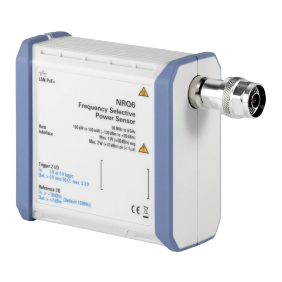
The printed document is delivered with the R&S NRQ6. 1.1.7 Data Sheets and Brochures The data sheet contains the technical specifications of the R&S NRQ6. It also lists the options and their order numbers, and optional accessories. The brochure provides an overview of the instrument and deals with the specific char- acteristics. - Page 11 ® Preface R&S NRQ6 Key Features ● Measurements in low RF level ranges that are beyond the range of classical power meters. Faster measurements in the RF level range close to the lower boundary of classical power meters. ● Frequency selective measurements with adjustable bandwidth including a built-in ACLR measurement function For a detailed specification, refer to the data sheet.
-
Page 12: Safety Information
R&S NRQ6 2 Safety Information The product documentation helps you use the R&S NRQ6 safely and efficiently. Follow the instructions provided here and in the printed "Basic Safety Instructions". Keep the product documentation nearby and offer it to other users. -
Page 13: Preparing For Use
Check the equipment for completeness using the delivery note and the accessory lists for the various items. Check the R&S NRQ6 for any damage. If there is damage, immediately contact the carrier who delivered the power sensor. Make sure not to dis- card the box and packing material. -
Page 14: Important Aspects For Test Setup
Risk of damage due to insufficient airflow If the R&S NRQ6 is run with insufficient airflow for a longer period, the R&S NRQ6 overheats. Overheating can disturb the operation, even cause damage and lead to wrong measurement results. -
Page 15: Connecting To A Power Supply
Preparing for Use R&S NRQ6 Connecting to a Power Supply To connect to the DUT For connecting the R&S NRQ6 to a DUT, use the RF connector of the R&S NRQ6. For details, see Chapter 4.1, "RF Connector", on page 26. -
Page 16: Connecting To A Controlling Host
Chapter 4.3, "LAN PoE+ Interface", on page 27. 2. Connect one end of the cable to the LAN interface of the R&S NRQ6. 3. Connect the other end of the cable to one of the following: ● PoE+ port of a LAN switch: Chapter 3.6.1.1, "Setup with a PoE+ Ethernet... -
Page 17: Setup With A Poe+ Ethernet Switch
DUT", on page 14. 2. Connect the RJ.45 Ethernet connector of the R&S NRQ6 to an Ethernet switch that supports PoE+ power delivery. 3. Connect the computer to the Ethernet switch. 4. Establish a connection between the R&S NRQ6 and the network, see Chap- ter 3.6.1.4, "Establishing a... -
Page 18: Setup With A Poe+ Injector And A Non-Poe+ Ethernet Switch
DUT", on page 14. 2. Connect the RJ.45 Ethernet connector of the R&S NRQ6 to the output of the PoE+ injector. 3. Connect the PoE+ injector to a power supply. 4. Connect the input of the PoE+ injector to the non-PoE+ Ethernet switch. -
Page 19: Setup With A Poe+ Injector
DUT", on page 14. 2. Connect the RJ.45 Ethernet connector of the R&S NRQ6 to the output of the PoE+ injector. 3. Connect the PoE+ injector to a power supply. 4. Connect the computer to the input of the PoE+ injector. - Page 20 ● <serial number> is the individual serial number of the R&S NRQ6. The serial number is printed on the bar code sticker at the rear side of the R&S NRQ6. It is the third part of the device ID: ID: 1421.3509K02 - 101441 - Zd...
-
Page 21: Computer Using A Usb Connection
3.6.2 Computer Using a USB Connection You can connect an R&S NRQ6 to a computer using the host interface and control it as described in Chapter 5, "Operating Concepts",... - Page 22 5 = USB connector 6 = Computer with installed VISA driver or R&S NRP Toolkit 7 = PoE+ injector 8 = AC supply 1. Connect the R&S NRQ6 to the signal source (DUT), see Chapter 3.4, "Connecting to a DUT", on page 14.
- Page 23 3.6.2.2 R&S NRP‑Z5 Sensor Hub Setup The R&S NRP‑Z5 sensor hub (high-speed USB 2.0) can host up to four R&S NRQ6 power sensors and provides simultaneous external triggering to all connected sensors. It comes with an external power supply unit, a power cable and a USB cable.
-
Page 24: R&S Nrx Base Unit
R&S NRP‑Z5 to the trigger device using a BNC cable. 3.6.3 R&S NRX Base Unit You can use an R&S NRX base unit as controlling host. Connect the R&S NRQ6 to the R&S NRX using the host interface. The R&S NRX supports the configuration of 2 directly connected R&S NRQ6, if enhanced accordingly. - Page 25 Insert this connector into one of the sensor ports of the R&S NRX. ► If you want to disconnect the cable from the host interface of the R&S NRQ6: a) Loosen the union nut of the screw-lock cable connector.
-
Page 26: S Nrq6 Tour
30 4.1 RF Connector See (1) in Figure 4-1. The male N connector is used to connect the R&S NRQ6 to the device under test (DUT) or a signal generator, see Chapter 3.4, "Connecting to a DUT", on page 14. -
Page 27: Status Information
LAN PoE+ Interface Risk of overloading the sensor Using the R&S NRQ6 at a level above its upper measuring limit can damage the sen- sor head. To avoid this risk, make sure not to exceed the test limit. 4.2 Status Information... - Page 28 Power Supply", on page 15. The power delivery at a USB host interface is not sufficient to run the R&S NRQ6 prop- erly. Therefore, you cannot use it as power supply for the R&S NRQ6. Figure 4-2: LAN [PoE+] interface...
-
Page 29: Host Interface
4.4 Host Interface See (4) in Figure 4-1. The 8-pole male sensor connector (M12) is used to connect the R&S NRQ6 to a com- puter or an R&S NRX base unit. Further information: ● Chapter 3.6.1, "Computer Using a LAN Connection",... -
Page 30: Clock I/O (Clk)
See (9, 10) in Figure 4-1. The R&S NRQ6 has fan openings on the top and on the bottom of the casing. When connecting the R&S NRQ6, be careful to allow sufficient airflow as specified in Chap- ter 3.4, "Connecting to a DUT",... -
Page 31: Operating Concepts
Chapter 5.4, "Remote Control", on page 39 Also, the R&S NRQ6 is supported by the R&S Power Viewer. The R&S Power Viewer is provided on your documentation CD-ROM and on the Rohde & Schwarz website as a separate standalone installation package. -
Page 32: R&S Nrp Toolkit For Windows
® Operating Concepts R&S NRQ6 R&S NRP Toolkit – Microsoft Windows Vista 32/64-bit – Microsoft Windows 7 32/64-bit – Microsoft Windows 8/ 8.1 32/64-bit – Microsoft Windows 10 32/64-bit ● For information on other operating systems, see Chapter 5.1.1, "Versions and Downloads",... -
Page 33: Browser-Based User Interface
With the integrated, browser-based graphical user interface of the R&S NRQ6, you can easily configure the settings and measure in the provided measurement modes. Open a web browser on your controlling host and connect to the R&S NRQ6. No extra instal- lation is required. -
Page 34: Layout Of The Main Dialog
Chapter 3.4, "Connecting to a DUT", on page 14. To display the Web user interface 1. Open a supported web browser. 2. Enter the hostname of the R&S NRQ6 you want to connect to. See Chap- ter 3.6.1.5, "Using Hostnames", on page 20. - Page 35 27. You can also display detailed information. Chapter 15.2, "Error Messages", on page 195. If the R&S NRQ6 is in remote mode, the status is displayed next to the status LED, see Figure 5-2. Sensor information (3) in Figure 5-1 Serial number of the R&S NRQ6 and installed firmware version...
-
Page 36: Tooltips
® Operating Concepts R&S NRQ6 Browser-Based User Interface Top pane (4) in Figure 5-1 Stays always visible. Chapter 7, "Adapting to the Test Signal", on page 49. Navigation pane (5) in Figure 5-1 For displaying measurement and system settings in the settings pane. -
Page 37: Setting Parameters
® Operating Concepts R&S NRQ6 Browser-Based User Interface Table 5-1: Icons for chart analysis Icon Description Downloads the chart in PNG format. Zooms into the selected window. Moves the chart in the direction of both axes. Enlarges the chart. Minimizes the chart. -
Page 38: R&S Nrx
® Operating Concepts R&S NRQ6 R&S NRX Quantity Short forms * Corresponding unit Time μs * Both capital and small letters are accepted. ► If you want to change a number, you can also: ● Use the spinner. One click changes the number by one increment. If you keep the arrow pressed, you can quickly scroll through the possible values. -
Page 39: Remote Control
For a detailed description of how to measure in this setup, refer to the user manual of the R&S NRX. 5.4 Remote Control You can remote control the R&S NRQ6 easily. The change to remote control occurs "on the fly". Switching to remote control 1. - Page 40 Figure 5-2: Locked web user interface during remote control Returning to manual operation (local) ► Press [Esc] at the controller keyboard. The R&S NRQ6 changes into local mode. The lock of the web user interface is removed. Further information: ●...
-
Page 41: Measurement Basics
RBW > 40 MHz, the R&S NRQ6 works in zero-IF mode. 6.2 Measurement Procedure in Principle Unlike thermal or diode-based power sensors, the R&S NRQ6 is frequency selective. That means, you go about measuring differently than you are accustomed from the conventional power sensors. -
Page 42: Measurement Duration
93. 5. Start the measurement. To get measurement results quickly, the R&S NRQ6 offers numerous autoset features. In the web user interface, several settings are bundled together and controlled by an "Autoset" button. In remote control, each automatic setting is executed by a separate command. -
Page 43: Improving Measurement Results
® Measurement Basics R&S NRQ6 Impact of Measurement Parameters on Noise Averaging For non-periodic signals, disable averaging entirely and choose the aperture time according to the desired total measurement duration. This approach is most efficient since it minimizes any waiting or processing times in the sensor. - Page 44 R&S NRQ6 with a conventional 3-path-diode sensor that has a class leading dynamic range. Unlike the 3-path diode sensor, the R&S NRQ6 has no auto-averaging feature. Therefore, you have to define the measure- ment time manually when measuring with the R&S NRQ6.
-
Page 45: Potential Sources Of Error
Leakage......................46 6.6.1 Spurious Response Frequencies The hardware design of the R&S NRQ6 differs fundamentally from a spectrum ana- lyzer. Therefore, the R&S NRQ6 cannot provide a similar level of spurious response rejection. For isolated signals with small bandwidths and correctly specified measure- ment frequencies, that is not a problem. -
Page 46: Lo Leakage
For the 3rd harmonic, the image suppression of the left sideband is about 9.5 dBc. For the 5th harmonic, the image suppression of the right sideband is about 14 dBc. The exact value depends on the frequency response of the R&S NRQ6. 6.6.2 LO Leakage In a receiver-based power sensor, signal leakage paths can occur. - Page 47 ® Measurement Basics R&S NRQ6 Potential Sources of Error is a signal generator with level control, the LO leakage of the R&S NRQ6 can lead to a wrong level setting. Example: LO frequency and harmonics Settings: ● Carrier frequency of the applied signal: 800 MHz ([SENSe<Sensor>:]FREQuency[:CENTer]...
- Page 48 ® Measurement Basics R&S NRQ6 Potential Sources of Error The black line represents the LO leakage at 0 dB RF attenuation. The blue line repre- sents the LO leakage at 30 dB RF attenuation. User Manual 1178.3692.02 ─ 06...
-
Page 49: Adapting To The Test Signal
Automatic Settings 7 Adapting to the Test Signal The R&S NRQ6 is a frequency selective power sensor. Before starting a measure- ment, you need to take the test signal and its properties into account. You can do that either automatically by using the autoset function, or by setting the fre- quency, filter, bandwidth and attenuation manually. -
Page 50: Frequency Configuration
The center frequency defines the mixing frequency in the downconversion process. Signals outside of the analysis bandwidth are filtered out. However, the R&S NRQ6 is sensitive to signals at frequencies related to the harmonics of the conversion fre- quency. -
Page 51: Frequency Adjustment For Narrowband Measurements
You can synchronize the reference frequencies of the R&S NRQ6 and the signal source. Make sure that center frequency is specified accurately. Use the REF connector of the R&S NRQ6 to lock the R&S NRQ6 to the reference fre- quency of the signal source or vice versa. -
Page 52: Resolution Bandwidth Filters
-120 dBm mum bandwidth 7.3 Resolution Bandwidth Filters The R&S NRQ6 supports different filter types. Each filter type is optimized for a differ- ent goal. Thus, it is possible to adapt the R&S NRQ6 to various measurement situa- tions. 7.3.1 Filter Characteristics... -
Page 53: Automatic Filter Type Selection
7-4. 7.3.2 Automatic Filter Type Selection In many situations, it is appropriate to let the R&S NRQ6 automatically choose the filter type for the measurement. The selection process is based on the currently selected measurement mode and, for some modes, also on the resolution bandwidth. -
Page 54: Choosing The Correct Filter Type
® Adapting to the Test Signal R&S NRQ6 Resolution Bandwidth Filters 7.3.3 Choosing the Correct Filter Type You can choose from a large variety of filters, as listed in Table 7-4. Not every filter type is suitable for every measurement. - Page 55 ® Adapting to the Test Signal R&S NRQ6 Resolution Bandwidth Filters Filter type Entered Pass BW 3 dB BW Stop BW Output Rise time Filter set- Equivalent sample rate tling time noise BW 27.0 μs Flat 20 kHz 20.0 kHz 25.0 kHz...
-
Page 56: Rf Input Attenuation
® Adapting to the Test Signal R&S NRQ6 RF Input Attenuation Filter type Entered Pass BW 3 dB BW Stop BW Output Rise time Filter set- Equivalent sample rate tling time noise BW Normal 200 Hz 200.0 Hz 1.0 kHz 2.1 kHz... -
Page 57: Top Pane Parameters
® Adapting to the Test Signal R&S NRQ6 Top Pane Parameters 7.5 Top Pane Parameters Access: main dialog of the web user interface > top pane In the web user interface, these settings are grouped in the top pane. Autoset.......................... 57 Signal Check......................... - Page 58 ® Adapting to the Test Signal R&S NRQ6 Top Pane Parameters Within the chart, the cursor becomes a crosshair. The x-position (frequency) of the crosshair is shown on black background, the y-position (power) is shown on blue. Frequency Sets the carrier frequency of the applied signal. This value is used for frequency response correction of the measurement result.
- Page 59 ® Adapting to the Test Signal R&S NRQ6 Top Pane Parameters Remote command: on page 119 [SENSe<Sensor>:]BANDwidth:RESolution:TYPE:AUTO[:STATe] <Filter type> ← Filter / Bandwidth Only available if "Manual" is set under "<State>" on page 58. Sets the filter type for resolution bandwidth filter. The filter bandwidth is not affected.
-
Page 60: Measurement Modes And Result Displays
Measuring Modulated Signals.................62 ● Continuous Average Parameters................62 ● Continuous Average Result Display................64 8.1.1 Averaging Domains In continuous average and trace mode, the R&S NRQ6 supports three different aver- aging domains with the following characteristics. User Manual 1178.3692.02 ─ 06... - Page 61 ® Measurement Modes and Result Displays R&S NRQ6 Continuous Average Mode Table 8-1: Averaging domains Power averaging Logarithmic aver- Amplitude averag- aging Command option "Power" "Video" "Linear" Averaging unit Watt Measurement bias caused by noise High Medium floor Measurement uncertainty caused...
-
Page 62: Measuring Modulated Signals
® Measurement Modes and Result Displays R&S NRQ6 Continuous Average Mode Signal type "Averaging Domain" Explanation Continuous wave (CW) "Video" No noticeable measurement bias for a signal-to- noise ratio equal to and above 8 dB. Increase in measurement uncertainty is negligible. - Page 63 ® Measurement Modes and Result Displays R&S NRQ6 Continuous Average Mode Averaging Domain......................63 Moving Average......................64 Aperture Time........................64 Duty Cycle........................64 dBm / Watt / dBμV......................64 Autoset Starts a continuous measurement. Remote command: TRIGger:SOURce IMMediate INITiate:CONTinuous Trigger Mode "Trigger Mode" on page 88.
-
Page 64: Continuous Average Result Display
Sets the duty cycle for measuring pulse-modulated signals. The duty cycle defines the percentage of one period during which the signal is active. If the duty cycle is enabled, the R&S NRQ6 takes this percentage into account when calculating the signal pulse power from the average power. -
Page 65: Trace Mode
Trace Mode 8.2 Trace Mode In this mode, the R&S NRQ6 measures power over time. The number of measurement points and the measurement time is defined. The length of an individual measurement is determined from the ratio of total time and the defined number of measurement points. - Page 66 ® Measurement Modes and Result Displays R&S NRQ6 Trace Mode dBm / Watt / dBμV......................67 Trace Offset........................67 Time/Div........................67 Autoset Adjusts the following: ● Adjusts the trace settings to the current signal. ● Optimizes the scaling of the x- and y-axes.
-
Page 67: Trace Result Display
® Measurement Modes and Result Displays R&S NRQ6 Trace Mode Moving Averaging "Moving Average" on page 64. Remote command: on page 138 [SENSe<Sensor>:]TRACe:AVERage:TCONtrol Autoscale Optimizes the y-axis scaling. dBm / Watt / dBμV "dBm / Watt / dBμV" on page 64. -
Page 68: Aclr Mode
® Measurement Modes and Result Displays R&S NRQ6 ACLR Mode For all other actions, use the toolbar in the upper right corner of the chart. See Chap- ter 5.2.3, "Toolbar in Charts", on page 36. 8.3 ACLR Mode In this mode, the adjacent channel leakage ratio (ACLR) is displayed. The ACLR is measured by an FFT analysis of a signal wide enough to contain all 5 channels. -
Page 69: Aclr Result Display
® Measurement Modes and Result Displays R&S NRQ6 ACLR Mode Remote command: TRIGger:SOURce IMMediate INITiate:CONTinuous Trigger Mode "Trigger Mode" on page 88. Trigger Level "Trigger Level" on page 88. Trigger Source "Trigger Source" on page 88. Trigger Delay Negative trigger delays are not supported. -
Page 70: I/Q Trace Mode
(R&S VSE) from Rohde & Schwarz. An application sheet describes the use of the R&S NRQ6 as an I/Q data source for the software R&S VSE vector signal explorer. It has the title "VSE Feed (I/Q Capturing)" and is available at: www.rohde-schwarz.com/manual/NRQ6... - Page 71 Setup for calibration Figure 8-2: Calibrating the system 1 = Signal generator (signal source) 2 = External reference fed into the reference clock of the master R&S NRQ6 3 = Power splitter 4 = RF connector 5 = R&S NRQ6...
- Page 72 NRQ6 I/Q Trace Mode Configuration for calibration 1. Enable the use of an external reference clock for the R&S NRQ6, to which the external reference is fed. 2. Establish a master/slave relationship for triggering: a) Configure the R&S NRQ6 that is fed the external reference as master.
-
Page 73: I/Q Trace Parameters
1. Measure the phase difference between the two ports of the DUT. 2. Use the calibration data to eliminate the phase difference caused by the R&S NRQ6 and to obtain the relative phase difference between the DUT ports. An application sheet describes the calibration of active antenna modules for beam- forming. - Page 74 ® Measurement Modes and Result Displays R&S NRQ6 I/Q Trace Mode Desired Sample Rate....................74 Used Sample Rate......................75 Sync Mode........................75 Capture I/Q Samples.....................75 Autoset Adjusts the trace settings to the current signal. Remote command: TRIGger:LEVel:AUTO ONCE [SENSe<Sensor>:]TRACe:TIME:AUTO ONCE...
-
Page 75: Power Servoing
129 FORMat[:DATA] on page 123 INITiate[:IMMediate] on page 128 [SENSe<Sensor>:]TRACe:IQ:DATA? 8.5 Power Servoing Requires the power servoing option (R&S NRQ6-K2). For information on the option management, see Chapter 10.1, "Option Management", on page 102. User Manual 1178.3692.02 ─ 06... - Page 76 1. Connect the instruments as shown in Figure 8-4. 2. Make sure to connect the TRIG2 connector of theR&S NRQ6 to the USER 2 con- nector of the R&S SGT100A. 3. Connect all instruments and the computer to the local network.
- Page 77 ® Measurement Modes and Result Displays R&S NRQ6 Power Servoing Remote commands on page 121 [SENSe<Sensor>:]FUNCtion on page 159 SYSTem:COMMunicate:PSERvoing:BCLock on page 159 SYSTem:COMMunicate:PSERvoing:TPATtern User Manual 1178.3692.02 ─ 06...
-
Page 78: Measurement Configuration
84 9.1.1 Controlling the Measurement Results The R&S NRQ6 can cope with the wide range of measurement scenarios with the help of the so-called "termination control". Depending on how fast your measurement results change, you can define, how the measurement results are output. -
Page 79: Interplay Of The Controlling Mechanisms
® Measurement Configuration R&S NRQ6 Controlling the Measurement Repeating termination control Outputs a measurement result when the entire measurement has been completed. This means that the number of measurement cycle repetitions is equal to the set aver- age count. If the average count is large, the measurement time can be very long. - Page 80 ® Measurement Configuration R&S NRQ6 Controlling the Measurement Example: Repeating termination control Further settings for this example: ● [SENSe<Sensor>:]TRACe:AVERage:TCONtrol REPeat ● [SENSe<Sensor>:]AVERage:COUNt The measurement is started by the trigger event. One measurement lasts as long as the defined aperture time. As defined by the average count, after 4 measurements, the result is averaged and available.
- Page 81 After 4 measurements, when the average count is reached, settled data are available. When the trigger count is reached (TRIGger:COUNt), the R&S NRQ6 returns to the idle state.
- Page 82 ® Measurement Configuration R&S NRQ6 Controlling the Measurement Example: Repeating termination control Further settings for this example: ● [SENSe<Sensor>:]AVERage:TCONtrol REPeat Every measurement is started by a trigger event and lasts the defined aperture time. During a measurement, the trigger synchronization is high (TRIGger:SYNC:STATe ON).
- Page 83 ® Measurement Configuration R&S NRQ6 Controlling the Measurement Example: Moving termination control Further settings for this example: ● [SENSe<Sensor>:]AVERage:TCONtrol MOVing ● [SENSe<Sensor>:]AVERage:COUNt Every measurement is started by a trigger event and lasts the defined aperture time. During a measurement, the trigger synchronization is high (TRIGger:SYNC:STATe ON).
-
Page 84: Trigger Settings
For average count 1, the setting of the termination control has no impact. In both cases, the measurement runs for the duration of one aperture time. Then, settled data are available, and the R&S NRQ6 returns to the idle state. ≠ IMMEDiate) -
Page 85: Trigger Sources
® Measurement Configuration R&S NRQ6 Trigger Settings ● Measuring The power sensor is measuring data. It remains in this state during the measure- ment. When the measurement is completed, it exits this state immediately. 9.2.2 Trigger Sources The possible trigger conditions and the execution of a trigger depend on the selected trigger mode and trigger source. -
Page 86: Hold-Off Time
® Measurement Configuration R&S NRQ6 Trigger Settings Figure 9-1: Significance of the dropout time The RF power between the slots is below the threshold defined by the trigger level and the trigger hysteresis. Therefore, the trigger hysteresis alone cannot prevent triggering at B or at C. -
Page 87: Trigger Jitter
CUV?. If MEAS is returned, this method can be used. 9.2.6 Trigger Master Usage If the R&S NRQ6 is the trigger master, the R&S NRQ6 outputs a digital trigger signal in sync with its own trigger event. The trigger signal is output at the selected port, "Host Interface"... - Page 88 ® Measurement Configuration R&S NRQ6 Trigger Settings Trigger Dropout......................89 Trigger Holdoff.......................89 Trigger Hysteresis......................89 Master Port........................90 Trigger 2 I/O Impedance....................90 Master State........................90 Sync. State........................90 Trigger Mode Controls the trigger execution. See also Chapter 9.2.2, "Trigger Sources", on page 85.
- Page 89 ® Measurement Configuration R&S NRQ6 Trigger Settings Remote command: on page 148 TRIGger:SOURce Trigger Delay Available if: ● "Auto", "Single" or "Normal" is set under "Trigger Mode" on page 88. ● "Internal", "External 1" or "External 2" is set under "Trigger Level"...
- Page 90 "Master State" on page 90. ● "Master" is set under "Sync Mode" on page 75. Selects the port where the R&S NRQ6 outputs a digital trigger signal. See Chap- ter 9.2.6, "Trigger Master Usage", on page 87. Remote command: on page 147...
-
Page 91: Correction Settings
10 dB above the lower measurement range limit. 9.3.1.2 Noise Correction The inherent noise power of the R&S NRQ6 is available as a reference value. If you enable the noise correction, this noise power is subtracted from the measured power. User Manual 1178.3692.02 ─ 06... -
Page 92: Corrections In The If Path
3 dB frequency set to 1.166 kHz. For measuring multicarrier signals in zero-IF mode at low signal levels, enable the DC reject filter and set the LO frequency of the R&S NRQ6 in a space between two carri- ers. User Manual 1178.3692.02 ─ 06... - Page 93 DC zeroing reduces the DC offset in the current measurement configuration. It is referred to the current bandwidth or frequency config- uration of the R&S NRQ6. 1. Make sure that the current settings are fitting for the measurement you want to per- form.
-
Page 94: Correction Parameters
® Measurement Configuration R&S NRQ6 Correction Settings 2. Start DC zeroing. Web user interface: "DC Zeroing" on page 96 Remote control: CALibration<Channel>:IQOFfset[:AUTO] 9.3.3 Correction Parameters Access: main dialog of the web user interface > navigation pane > "Correction" Path......................... 94 └... - Page 95 ® Measurement Configuration R&S NRQ6 Correction Settings Remote command: on page 151 [SENSe<Sensor>:]POWer:NCORrection[:STATe] Level Offset ← RF Path For background information, see Chapter 9.3.1.3, "Accounting for External Losses", on page 92. <State> ← Level Offset ← RF Path Enables or disables the offset correction.
-
Page 96: Mixer Settings
Parameters....................96 9.4.1 Local Oscillator Signal By default, the R&S NRQ6 generates its local oscillator (LO) signal internally. You can output the local oscillator signal at the LO connector and use it for other devices. Also, you can supply an external signal using the LO connector. For the frequency range, Table 9-2. - Page 97 ® Measurement Configuration R&S NRQ6 Mixer Settings Local Oscillator (LO) - Source..................97 SMA Connector Out...................... 97 └ I/O......................97 └ Output Frequency, Input Frequency............... 97 Intermediate........................98 └ Sideband......................98 └ Left, Right......................98 Frequency (IF) - Frequency..................98 Frequency Tracking.......................98 └ Switch......................98 └...
-
Page 98: Sensor Settings
® Measurement Configuration R&S NRQ6 Sensor Settings Intermediate Groups settings of the intermediate frequency sideband. Sideband ← Intermediate Enables or disables the automatic setting of the intermediate frequency sideband. Remote command: [SENSe<Sensor>:]FREQuency:CONVersion:MIXer:IF:SIDeband:AUTO[: on page 152 STATe] Left, Right ← Intermediate Available if "Manual"... -
Page 99: Clock Source Configuration
Measurement Configuration R&S NRQ6 Sensor Settings 9.5.1 Clock Source Configuration By default, the R&S NRQ6 generates its conversion frequency, sampling clock and ref- erence clock internally. Alternatively, you can use external clock sources, see Table 9-2. Table 9-1: Internal clock frequencies... - Page 100 └ Clock I/O....................... 101 Clock Distribution Mode - Use Ext. Sampling Clock Requires the phase coherent measurements option (R&S NRQ6-K3). Configures the usage of the external sampling clock. ● "Off" Uses the internally generated 10 MHz reference signal to derive the sampling clock signal.
- Page 101 ® Measurement Configuration R&S NRQ6 Sensor Settings Clock I/O ← SMA Connector Out If the CLK connector is used as an output, enables or disables the output signal. See also Table 9-2. Remote command: on page 155 [SENSe<Sensor>:]SAMPling:CLKio:OUTPut[:STATe] User Manual 1178.3692.02 ─ 06...
-
Page 102: System Configuration
® System Configuration R&S NRQ6 Option Management 10 System Configuration The settings for the system configuration do not directly affect the measurement. Remote command reference: ● Chapter 12.10, "Configuring the System", on page 155 10.1 Option Management Optional features are available as options and are part of the firmware package. If you want to use an optional feature, you buy the option and, in return, receive a license key. -
Page 103: System Parameters
Select the RSI file you want to install. 7. Click "Apply". 8. Click "Reboot". The R&S NRQ6 performs a reboot. 9. Check whether the option is active. The name of the option is displayed under "Installed Options", for example "NRQ-K1". - Page 104 Sensor Preset Click the "RST" button to perform a preset. Use the preset functionality to set the R&S NRQ6 to a well defined state. This allows you to change parameter values from well defined starting point. User Manual 1178.3692.02 ─ 06...
- Page 105 Remote command: on page 161 SYSTem:FWUPdate on page 161 SYSTem:FWUPdate:STATus? Reboot Sensor Reboots the R&S NRQ6. When the reboot is completed, press [F5] to reload the web browser page. Remote command: on page 166 SYSTem:REBoot Installed Options Lists all software options that are activated on the R&S NRQ6. See also Chapter 10.1,...
- Page 106 R&S NRQ6 System Parameters Device ID ← Enter License Key Displays the identification number that is unique for each R&S NRQ6. The string has the following structure: 1421.3509K02/<serial number> You need the device ID to order an option. Remote command:...
-
Page 107: Firmware Update
Interrupting the power supply during the firmware update most likely leads to an unusa- ble power sensor that needs to be sent in for maintenance. You can use the following methods to update the firmare installed on the R&S NRQ6: ●... -
Page 108: Using The Firmware Update For Nrp Family Program
® Firmware Update R&S NRQ6 Updating the Firmware 1. Connect the power sensor to the computer as described in "To connect to a LAN PoE+ interface" on page 16. 2. Open the web user interface as described in Chapter 5.2, "Browser-Based User Interface",... - Page 109 ® Firmware Update R&S NRQ6 Updating the Firmware 2. Connect the power sensor to the computer as described in Chapter 3.6.1, "Com- puter Using a LAN Connection", on page 16. 3. Start the Firmware Update for NRP Family program: "Start" menu > "NRP-Toolkit" > "Firmware Update".
- Page 110 107 and "Checking the prerequisites" on page 108. 10. If you use the web user interface to operate the R&S NRQ6, press [F5] to reload the web page. Firmware Update for NRP Family over USB 1. Check the prerequisites, see "Checking the prerequisites"...
- Page 111 ® Firmware Update R&S NRQ6 Updating the Firmware 4. If the sensor you want to update is not listed, perform one of the following actions: a) Click "Rescan" to search for attached sensors. b) Check whether all necessary drivers are installed on the computer.
-
Page 112: Using Remote Control
R&S NRQ6 Updating the Firmware 10. If you use the web user interface to operate the R&S NRQ6, press [F5] to reload the web page. 11.2.3 Using Remote Control If you want to integrate a firmware update function in an application, use SYSTem: on page 161. -
Page 113: Remote Control Commands
● Conformity Commands that are taken from the SCPI standard are indicated as SCPI con- firmed. All commands used by the R&S NRQ6 follow the SCPI syntax rules. ● Asynchronous commands A command which does not automatically finish executing before the next com- mand starts executing (overlapping command) is indicated as an Asynchronous command. -
Page 114: Common Commands
® Remote Control Commands R&S NRQ6 Common Commands 12.2 Common Commands The common commands are taken from the IEEE 488.2 (IEC 625–2) standard. The headers of these commands consist of an asterisk * followed by three letters..........................114 *CLS ..........................114... -
Page 115: Idn
® Remote Control Commands R&S NRQ6 Common Commands Returns the contents of the event status register in decimal form (0 to 255) and subse- quently sets the register to zero. Usage: Query only *IDN? IDeNtification query Returns a string with information on the sensor's identity (device identification code). In addition, the version number of the installed firmware is indicated. -
Page 116: Pre
® Remote Control Commands R&S NRQ6 Common Commands *PRE <register> Parallel poll Register Enable Sets the parallel poll enable register to the specified value or queries the current value. Parameters: <register> Range: 0 to 255 *RST: *RST Reset Sets the instrument to a defined default status. The default settings are indicated in the description of commands. -
Page 117: Adapting To The Test Signal
® Remote Control Commands R&S NRQ6 Adapting to the Test Signal *TST? Selftest query Triggers a self test of the instrument and outputs an error code in decimal form. 0 indi- cates that no errors have occurred. Example: *TST? Query... - Page 118 ® Remote Control Commands R&S NRQ6 Adapting to the Test Signal ................. 120 [SENSe<Sensor>:]FREQuency[:CENTer] ................120 [SENSe<Sensor>:]INPut:ATTenuation ..............121 [SENSe<Sensor>:]INPut:ATTenuation:AUTO [SENSe<Sensor>:]ADJust[:ALL] <state> Adjusts center frequency and bandwidth settings to the test signal. Executed once. Parameters: <state> *RST: Example: ADJ ONCE Manual operation: "Autoset"...
- Page 119 ® Remote Control Commands R&S NRQ6 Adapting to the Test Signal [SENSe<Sensor>:]BANDwidth:RESolution:CUV? <bandwidth> Queries the currently used resolution bandwidth. Query parameters: <bandwidth> Range: 10 to 400e6 Default unit: Frequency Example: BAND:RES:CUV? Usage: Query only Manual operation: "<Bandwidth>" on page 59 [SENSe<Sensor>:]BANDwidth:RESolution:TYPE <select>...
- Page 120 ® Remote Control Commands R&S NRQ6 Adapting to the Test Signal Parameters: <value> Range: 50 to 120e6 *RST: 22.6e6 Default unit: Frequency Example: BAND:SRAT 22600000 Manual operation: "Desired Sample Rate" on page 74 [SENSe<Sensor>:]BANDwidth:SRATe:CUV? Queries the currently used sample rate.
-
Page 121: Selecting A Measurement Mode
68. "POWer:AVG" Continuous average mode, see Chapter 8.1, "Continuous Aver- Mode", on page 60. "POW:SERV" Power servoing mode, see Chapter 8.5, "Power Servoing", on page 75. Requires the power servoing option (R&S NRQ6-K2). User Manual 1178.3692.02 ─ 06... -
Page 122: Starting And Ending A Measurement
123), the R&S NRQ6 goes into the idle state. IMMediate] If a continuous measurement is in progress (INITiate:CONTinuous on page 123 ON), the R&S NRQ6 waits for triggering and, if the trigger condition is met, starts a new measurement immediately. See also Chapter 9.2.1, "Trigger States", on page 84. - Page 123 INITiate:CONTinuous <state> Enables or disables the continuous measurement mode. In continuous measurement mode, the R&S NRQ6 does not reach the idle state after a measurement has been completed, but immediately executes another measurement cycle. If measuring in zero-IF mode (RBW > 40 MHz), consider to zero the power sensor (CALibration<Channel>:ZERO:AUTO...
-
Page 124: Measurement Results
® Remote Control Commands R&S NRQ6 Measurement Results 12.6 Measurement Results ● Results of All Kind....................124 ● Retrieving Continuous Average Results............... 124 ● Retrieving Trace Results..................126 ● Retrieving ACLR Results..................128 ● Retrieving I/Q Results................... 128 ● Configuring Results....................129 12.6.1 Results of All Kind... - Page 125 ® Remote Control Commands R&S NRQ6 Measurement Results ................ 125 FETCh<Sensor>:ARRay[:POWer][:AVG]? ............. 125 [SENSe<Sensor>:][POWer:][AVG:]BUFFer:CLEar ............125 [SENSe<Sensor>:][POWer:][AVG:]BUFFer:COUNt? ............125 [SENSe<Sensor>:][POWer:][AVG:]BUFFer:DATA? ...............125 [SENSe<Sensor>:][POWer:][AVG:]BUFFer:SIZE .............126 [SENSe<Sensor>:][POWer:][AVG:]BUFFer:STATe FETCh<Sensor>:ARRay[:POWer][:AVG]? Queries the last valid measurement result of a measurement with enabled result buffer. You can enable the buffer using [SENSe<Sensor>:][POWer:][AVG:]BUFFer:...
-
Page 126: Retrieving Trace Results
® Remote Control Commands R&S NRQ6 Measurement Results Parameters: <count> Range: 1 to 131072 *RST: Example: BUFF:SIZE 1 [SENSe<Sensor>:][POWer:][AVG:]BUFFer:STATe <state> Enables or disables the result buffer in continuous average mode. If enabled, all results generated by trigger events are collected in the buffer until it is full. - Page 127 ® Remote Control Commands R&S NRQ6 Measurement Results – Character # – Single digit ( 'n') which tells the number of following digits that is taken as the size of the content. – Number consisting of as many digits as 'n' specified ( 'LLLLL'). This number gives the size of the content ●...
-
Page 128: Retrieving Aclr Results
® Remote Control Commands R&S NRQ6 Measurement Results ● Single digit which tells the number of following digits that are taken as the number of contained float values ● As many digits as the number of digits for user data specified ('x'). These digits are... -
Page 129: Configuring Results
Specifies how the R&S NRQ6 sends the acquired I/Q data to the controlling host/ computer. In the R&S NRQ6, the acquired I/Q data is natively represented as pairs of I/Q sam- ples, stored as IEEE754 single precision (32-bit) float values. - Page 130 Block of binary values, 32-bit or 64-bit each; so-called "SCPI definite length block" 32 | 64 32-bit or 64-bit If you omit the length, the R&S NRQ6 sets the last used length. Example for REAL,32 format: #6768000..<binary float values>..Example for REAL,64 format: #71536000..<binary float values>..
-
Page 131: Calibrating And Zeroing
® Remote Control Commands R&S NRQ6 Calibrating and Zeroing Manual operation: "Capture I/Q Samples" on page 75 UNIT:POWer <unit> Sets the output unit for the measured power values. Parameters: <unit> DBM | W | DBUV *RST: Example: UNIT:POW DBM Manual operation: "dBm / Watt / dBμV"... - Page 132 ® Remote Control Commands R&S NRQ6 Calibrating and Zeroing CALibration<Channel>:IQOFfset[:AUTO] <state> Compensates for the internal DC voltage offset. Recommended for measurements in zero-IF mode (RBW > 40 MHz). See also Chapter 9.3.2.2, "DC Zeroing", on page 93. Suffix: <Channel> 1 to 4 Measurement channel if more than one channel is available.
-
Page 133: Running A Selftest
® Remote Control Commands R&S NRQ6 Running a Selftest *RST: *CLS Example: CAL1:ZERO:AUTO ONCE Performs zero calibration. Manual operation: "Zero Calibration" on page 94 "Implausible results in zero-IF mode" on page 197 12.8 Running a Selftest The selftest allows a test of the internal circuitry of the sensor. -
Page 134: Configuring Measurement Settings
® Remote Control Commands R&S NRQ6 Configuring Measurement Settings 12.9 Configuring Measurement Settings This chapter describes the measurement settings for all measurement modes. Further information: ● Chapter 8, "Measurement Modes and Result Displays", on page 60 ● Chapter 9, "Measurement Configuration",... - Page 135 ® Remote Control Commands R&S NRQ6 Configuring Measurement Settings Manual operation: "<Count>" on page 63 [SENSe<Sensor>:]AVERage:RESet Deletes all previous measurement results that the averaging filter contains and initial- izes the averaging filter. The filter length gradually increases from 1 to the set averag- ing factor.
- Page 136 Sets the duty cycle for measuring pulse-modulated signals. The duty cycle defines the percentage of one period during which the signal is active. If the duty cycle is enabled, the R&S NRQ6 takes this percentage into account when calculating the signal pulse power from the average power.
-
Page 137: Configuring A Trace Measurement
® Remote Control Commands R&S NRQ6 Configuring Measurement Settings Parameters: <duty_cycle> Range: 0.001 to 100.00 *RST: 1.00 Default unit: Percent Example: CORR:DCYC 1 Manual operation: "Duty Cycle" on page 64 [SENSe<Sensor>:]CORRection:DCYCle:STATe <state> Enables or disables the duty cycle correction for the measured value. - Page 138 ® Remote Control Commands R&S NRQ6 Configuring Measurement Settings ................... 139 [SENSe<Sensor>:]TRACe:POINts ..................139 [SENSe<Sensor>:]TRACe:TIME ................140 [SENSe<Sensor>:]TRACe:TIME:AUTO [SENSe<Sensor>:]TRACe:AVERage:COUNt <count> Sets the number of readings that are averaged for one measured value. The higher the count, the lower the noise, and the longer it takes to obtain a measured value.
- Page 139 TRAC:OFFS:TIME 1.0 [SENSe<Sensor>:]TRACe:RLENgth[:CUV]? The behavior of this query depends on the measurement mode. ● I/Q trace mode (R&S NRQ6-K1) Queries the number of samples in the current trace. ● Trace mode Queries the number of real result samples before they are reduced or interpolated to the number of trace points defined by [SENSe<Sensor>:]TRACe:POINts.
-
Page 140: Configuring An Aclr Measurement
® Remote Control Commands R&S NRQ6 Configuring Measurement Settings Parameters: <time> Range: 8.30E-09 to 30.0 *RST: 0.01 Default unit: Seconds Example: TRAC:TIME 0.01 Manual operation: "Time/Div" on page 67 "Implausible triggering" on page 197 [SENSe<Sensor>:]TRACe:TIME:AUTO <state> Sets the trace time automatically. -
Page 141: Configuring An I/Q Trace Mode
Default unit: Seconds ACLR:APER 0.001 Example: Manual operation: "Aperture Time" on page 69 12.9.4 Configuring an I/Q Trace Mode Requires the I/Q data interface (R&S NRQ6-K1). Further information: ● Chapter 8.4, "I/Q Trace Mode", on page 70 Web user interface: ●... -
Page 142: Configuring The Trigger
Chapter 9.2.6, "Trigger Master Usage", on page 87. Parameters: <mode> OFF | MASTer | SLAVe *RST: Example: TRACe:IQ:SYNC:MODE MAST Configures the R&S NRQ6 as master. Manual operation: "Sync Mode" on page 75 12.9.5 Configuring the Trigger Further information: ● Chapter 9.2.1, "Trigger States", on page 84 ●... -
Page 143: Trigger:atrigger:delay
® Remote Control Commands R&S NRQ6 Configuring Measurement Settings ......................148 TRIGger:SOURce ....................149 TRIGger:SYNC:PORT ....................149 TRIGger:SYNC:STATe TRIGger:ATRigger:DELay <delay> Effective only if on page 143 is set to ON. TRIGger:ATRigger:STATe Sets the delay between the artificial trigger event and the beginning of the actual mea-... -
Page 144: Trigger:delay
® Remote Control Commands R&S NRQ6 Configuring Measurement Settings This command is particularly useful in conjunction with buffered measurements. For example, to fill a buffer with a predefined size with measurements that have been trig- gered externally or by without having to start the measurement multiple times. -
Page 145: Trigger:holdoff
"Trigger Hysteresis" on page 89 TRIGger:IMMediate Causes a generic trigger event. The R&S NRQ6 leaves the waiting for trigger state immediately, irrespective of the trigger source and the trigger delay, and starts the measurement. This command is the only way to start a measurement if the trigger source is set to... -
Page 146: Trigger:jitter:method
® Remote Control Commands R&S NRQ6 Configuring Measurement Settings Queries the known trigger offset. TRIG:JITT? Example: Query 0.000000E+00 Result Usage: Query only TRIGger:JITTer:METHod <methode> Available in trace mode. Defines the method how to cope with the misalignment between the trigger event and the sample point. -
Page 147: Trigger:level:auto
TRIGger:MASTer:PORT <master_port> Effective only if the R&S NRQ6 is trigger master: ● TRIGger:MASTer:STATe ● [SENSe<Sensor>:]TRACe:IQ:SYNC:MODE MAST Selects the port where the R&S NRQ6 outputs a digital trigger signal. See Chap- ter 9.2.6, "Trigger Master Usage", on page 87. Parameters: <master_port>... -
Page 148: Trigger:master:state
® Remote Control Commands R&S NRQ6 Configuring Measurement Settings Example: TRIG:MAST:PORT EXT2 TRIG:SOUR EXT1 TRIG:MAST:STAT ON Manual operation: "Master Port" on page 90 TRIGger:MASTer:STATe <state> Enables or disables the trigger master state. See Chapter 9.2.6, "Trigger Master Usage", on page 87. -
Page 149: Configuring The Corrections
® Remote Control Commands R&S NRQ6 Configuring Measurement Settings Manual operation: "Autoset" on page 63 "Autoset" on page 66 "Autoset" on page 68 "Autoset" on page 74 "Trigger Mode" on page 88 "Trigger Source" on page 88 TRIGger:SYNC:PORT <sync_port> Selects the external connection for the sync output of the sensor. For more information, on page 149. - Page 150 ® Remote Control Commands R&S NRQ6 Configuring Measurement Settings ............150 [SENSe<Sensor>:]FILTer:DCReject:FCORner:CUV? ..............151 [SENSe<Sensor>:]FILTer:DCReject[:STATe] .............. 151 [SENSe<Sensor>:]POWer:NCORrection[:STATe] [SENSe<Sensor>:]CORRection:OFFSet <offset> Sets a fixed offset that is added to the measured value to account for external attenua- tion or amplification. See also Chapter 9.3.1.3, "Accounting for External...
-
Page 151: Configuring The Mixer
® Remote Control Commands R&S NRQ6 Configuring Measurement Settings [SENSe<Sensor>:]FILTer:DCReject[:STATe] <state> Available for resolution bandwidths > 40 MHz (zero-IF mode). Enables or disables the DC reject filter. Set the corner (cut-off) frequency points using [SENSe<Sensor>:]FILTer:DCReject:FCORner. See also Chapter 9.3.2.1, "DC Rejection",... -
Page 152: [Sense
® Remote Control Commands R&S NRQ6 Configuring Measurement Settings Usage: Query only Manual operation: "Frequency (IF) - Frequency" on page 98 [SENSe<Sensor>:]FREQuency:CONVersion:MIXer:IF:SIDeband <select> Sets the currently used intermediate frequency sideband. Parameters: <select> LEFT | RIGHt *RST: LEFT Example: FREQ:CONV:MIX:IF:SID RIGH Sets the right sideband.:]Frequency:conversion:mixer:if:sideband -
Page 153: [Sense
® Remote Control Commands R&S NRQ6 Configuring Measurement Settings *RST: FREQ:CONV:MIX:LO:OUTP OFF Example: Manual operation: "LO I/O" on page 97 [SENSe<Sensor>:]FREQuency:CONVersion:MIXer:LO:SOURce <source> Sets the local oscillator source. Parameters: <source> INTernal | EXTernal INTernal Uses the internal LO signal. EXTernal Uses the external LO signal fed into the LO connector. The inter- nal LO generation is disabled.:]Frequency:conversion:mixer:lo:source -
Page 154: Configuring The Sensor
................155 [SENSe<Sensor>:]ROSCillator:SOURce ............155 [SENSe<Sensor>:]SAMPling:CLKio:OUTPut[:STATe] [SENSe<Sensor>:]ROSCillator:PASSthrough <state> Requires the phase coherent measurements option (R&S NRQ6-K3). Configures the usage of the external sampling clock. Parameters: <state> Uses the internally generated 10 MHz reference signal to derive the sampling clock signal. -
Page 155: Configuring The System
® Remote Control Commands R&S NRQ6 Configuring the System Example: ROSC:REF:FREQ 10000000 Manual operation: "Reference Input" on page 100 [SENSe<Sensor>:]ROSCillator:REFio:OUTPut[:STATe] <state> If the REF connector is used as an output, enables or disables the output signal. See also Table 9-2. -
Page 156: System:communicate:network:ipaddress
SYSTem:RESTart ....................166 SYSTem[:SENSor]:NAME ......................167 SYSTem:SERRor? ................... 167 SYSTem:SERRor:LIST:ALL? ..................167 SYSTem:SERRor:LIST[:NEXT]? ......................167 SYSTem:VERSion? SYSTem:COMMunicate:NETWork:IPADdress <ipaddress> Effective only if is set to SYSTem:COMMunicate:NETWork:IPADdress:MODE STATic. Sets the IP address of the R&S NRQ6. Parameters: <ipaddress> User Manual 1178.3692.02 ─ 06... -
Page 157: System:communicate:network:ipaddress:gateway
® Remote Control Commands R&S NRQ6 Configuring the System Example: SYST:COMM:NETW:IPAD '192.168.10.29' Sets 192.168.10.29 as IP address. Manual operation: "IP Address" on page 104 SYSTem:COMMunicate:NETWork:IPADdress:GATeway <gateway> Effective only if is set to SYSTem:COMMunicate:NETWork:IPADdress:MODE STATic. Sets the address of the default gateway, that means the router that is used to forward traffic to destinations beyond the local network. -
Page 158: System:communicate:network:restart
® Remote Control Commands R&S NRQ6 Configuring the System Parameters: <netmask> The subnet mask consists of four number blocks separated by dots. Every block contains 3 numbers in maximum. Example: SYST:COMM:NETW:IPAD:SUBN:MASK '255.255.255.0' Sets 255.255.255.0 as subnet mask. Manual operation: "Subnet Mask"... -
Page 159: System:communicate:pservoing:bclock
The R&S NRQ6 performs the change of the hostname immediately after the command is sent. For this purpose, the R&S NRQ6 restarts its connection to the network, which can take several seconds. During this time, you cannot address the R&S NRQ6. After the restart, you can only address the R&S NRQ6 using the newly set hostname. -
Page 160: System:error:all
® Remote Control Commands R&S NRQ6 Configuring the System Suffix: <Channel> 1 to 4 Measurement channel if more than one channel is available. Usage: Query only SYSTem:ERRor:ALL? Queries all unread entries in the error/event queue and removes them from the queue. -
Page 161: System:error[:Next]
Response: No errors have occurred since the error queue was last read out. Usage: Query only SYSTem:FWUPdate <fwudata> Loads new operating firmware into the R&S NRQ6. Rohde & Schwarz provides the update file. For further details, see Chapter 11, "Firmware Update", on page 107. -
Page 162: System:help:headers
® Remote Control Commands R&S NRQ6 Configuring the System The result of the query is a readable string. SYST:FWUP:STAT? Example: Query "Success" Response Usage: Query only Manual operation: "Firmware Update" on page 105 SYSTem:HELP:HEADers? [<Item>] Returns a list of all SCPI commands supported by the sensor. -
Page 163: System:initialize
Coupling Cal Due Date TestLimit Uptime Example: SYST:INFO? Query "Manufacturer:Rohde & Schwarz Type: NRQ6 Stock Number:1421.3509K02 Serial: 900041 SW Build:02.10.19090301 MAC Address: 00:90:b8:1e: 57:19 Hostname:nrq6-900041 IP Address: 10.111.0.157 Sensor Name: NRQ6-900041 Technology: Frequency Selective Function: Power Terminating MinPower:1e-17 MaxPower: 0.1 MinFreq:5e+07 MaxFreq:6e+09 Resolution: 8.33333e-09 Impedance:... -
Page 164: System:language
® Remote Control Commands R&S NRQ6 Configuring the System The sensor loads the default settings for all test parameters in the same way as when using *RST. The sensor outputs a complete list of all supported commands and param- eters. The remote-control software can automatically adapt to the features of different types of sensors with different functionality. -
Page 165: System:license:key
® Remote Control Commands R&S NRQ6 Configuring the System Parameters: <mode> USER | SENSor *RST: SENSor SYSTem:LICense:KEY <key> Installs the license key for the option key management. To make the new option availa- ble, reboot the sensor using SYSTem:REBoot. Check the installed options using on page 115. -
Page 166: System:parameters
"Reboot Sensor" on page 105 "Reboot" on page 106 SYSTem:RESTart Restarts the firmware of the R&S NRQ6. Usage: Event SYSTem[:SENSor]:NAME <sensorname> Sets the sensor name. The sensor name is displayed in the title bar of the web user interface, see (1) in Figure 5-1. -
Page 167: System:serror
® Remote Control Commands R&S NRQ6 Configuring the System Example: SYST:NAME "InputModule-X5" Manual operation: "Sensor Name" on page 104 SYSTem:SERRor? Queries all static errors that are currently present. See also "Querying errors (remote control)" on page 195. Usage: Query only SYSTem:SERRor:LIST:ALL? Returns a list of all static errors that have occurred but have already been resolved. -
Page 168: Using The Status Register
® Remote Control Commands R&S NRQ6 Using the Status Register 12.11 Using the Status Register Contents: ● General Status Register Commands..............168 ● Reading Out the CONDition Part................168 ● Reading Out the EVENt Part.................169 ● Controlling the ENABle Part..................169 ●... -
Page 169: Reading Out The Event Part
® Remote Control Commands R&S NRQ6 Using the Status Register 12.11.3 Reading Out the EVENt Part STATus:DEVice[:EVENt]? STATus:OPERation:CALibrating[:SUMMary][:EVENt]? STATus:OPERation[:EVENt]? STATus:OPERation:LLFail[:SUMMary][:EVENt]? STATus:OPERation:MEASuring[:SUMMary][:EVENt]? STATus:OPERation:SENSe[:SUMMary][:EVENt]? STATus:OPERation:TRIGger[:SUMMary][:EVENt]? STATus:OPERation:ULFail[:SUMMary][:EVENt]? STATus:QUEStionable:CALibration[:SUMMary][:EVENt]? STATus:QUEStionable[:EVENt]? STATus:QUEStionable:POWer[:SUMMary][:EVENt]? STATus:QUEStionable:WINDow[:SUMMary][:EVENt]? Usage: Query only 12.11.4 Controlling the ENABle Part STATus:DEVice:ENABle <value> STATus:OPERation:CALibrating:ENABle <value>... -
Page 170: Controlling The Positive Transition Part
® Remote Control Commands R&S NRQ6 Using the Status Register STATus:QUEStionable:POWer:NTRansition <value> STATus:QUEStionable:WINDow:NTRansition <value> Parameters: <value> *RST: 12.11.6 Controlling the Positive Transition Part STATus:DEVice:PTRansition <value> STATus:OPERation:CALibrating:PTRansition <value> STATus:OPERation:PTRansition <value> STATus:OPERation:LLFail:PTRansition <value> STATus:OPERation:MEASuring:PTRansition <value> STATus:OPERation:SENSe:PTRansition <value> STATus:OPERation:TRIGger:PTRansition <value> STATus:OPERation:ULFail:PTRansition <value> STATus:QUEStionable:CALibration:PTRansition <value>... -
Page 171: Programming Examples
Feed for Vector Signal Explorer (VSE) Writes the measured I/Q data into a *.csv file. Requires the I/Q data interface (R&S NRQ6-K1). ● Phase analysis Requires the I/Q data interface (R&S NRQ6-K1) and the phase coherent measure- ments (R&S NRQ6-K3). User Manual 1178.3692.02 ─ 06... -
Page 172: Remote Control Basics
Apart from the USBTMC driver, which comes with the installation of the R&S NRP Toolkit, you do not have to install a separate driver. Setup 1. Connect the host interface of the R&S NRQ6 and the USB interface of the com- puter, see Chapter 3.6.2, "Computer Using a USB Connection",... -
Page 173: Ethernet Interface
0x015B is the product ID for the R&S NRQ6. 100001 is the serial number of the particular R&S NRQ6. 14.1.2 Ethernet Interface The Ethernet interface of the R&S NRQ6 allows you to integrate it in a local area net- work (LAN). Requirements ●... - Page 174 Remote Control Basics R&S NRQ6 Remote Control Interfaces and Protocols Setup 1. Using the Ethernet interface, connect the computer and the R&S NRQ6 to a local area network, see Chapter 3.6.1, "Computer Using a LAN Connection", on page 16. 2. Make sure that the R&S NRQ6 is powered by PoE+. For details, see "R&S NRQ6...
- Page 175 Example: A power sensor has the IP address 10.111.11.20; the valid resource string using VXI-11 protocol is: TCPIP::10.111.11.20::INSTR The DNS hostname is nrq6-100001; the valid resource string is: TCPIP::nrq6-100001::hislip0 (HiSLIP) TCPIP::nrq6-100001::inst0 (VXI-11) A raw socket connection can be established using: TCPIP::10.111.11.20::5025::SOCKET...
-
Page 176: Scpi Command Structure
® Remote Control Basics R&S NRQ6 SCPI Command Structure ● Supports simultaneous access of multiple users by providing versatile locking mechanisms. ● Usable for IPv6 or IPv4 networks. The HiSLIP data is sent to the device using the "fire and forget" method with immediate return. -
Page 177: Syntax For Common Commands
® Remote Control Basics R&S NRQ6 SCPI Command Structure 14.2.1 Syntax for Common Commands Common (=device-independent) commands consist of a header preceded by an aster- isk (*) and possibly one or more parameters. Examples: *RST RESET Resets the instrument. *ESE... -
Page 178: Scpi Parameters
® Remote Control Basics R&S NRQ6 SCPI Command Structure Optional mnemonics Some command systems permit certain mnemonics to be inserted into the header or omitted. These mnemonics are marked by square brackets in the description. The instrument must recognize the long command to comply with the SCPI standard. Some commands are considerably shortened by these optional mnemonics. - Page 179 ® Remote Control Basics R&S NRQ6 SCPI Command Structure Numeric values Numeric values can be entered in any form, i.e. with sign, decimal point and exponent. Values exceeding the resolution of the instrument are rounded up or down. The man- tissa can comprise up to 255 characters, the exponent must lie inside the value range -32000 to 32000.
- Page 180 ® Remote Control Basics R&S NRQ6 SCPI Command Structure Boolean Parameters Boolean parameters represent two states. The "ON" state (logically true) is represen- ted by "ON" or a numeric value 1. The "OFF" state (logically untrue) is represented by "OFF" or the numeric value 0. The numeric values are provided as the response for a query.
-
Page 181: Overview Of Syntax Elements
® Remote Control Basics R&S NRQ6 SCPI Command Structure Example: SYSTem:HELP:SYNTax:ALL? Response: #45168xxxxxxxx The ASCII character # introduces the data block. The next number indicates how many of the following digits describe the length of the data block. In the example, the 4 fol- lowing digits indicate the length to be 5168 bytes. -
Page 182: Responses To Queries
® Remote Control Basics R&S NRQ6 SCPI Command Structure Several commands in a command line must be separated by a semicolon ";". If the next command belongs to a different command system, the semicolon is followed by a colon. If the successive commands belong to the same system, having one or several levels in common, the command line can be abbreviated. -
Page 183: Status Reporting System
® Remote Control Basics R&S NRQ6 Status Reporting System Response: INT 14.3 Status Reporting System The status reporting system stores all information on the current operating state of the sensor, and on errors which have occurred. This information is stored in the status reg- isters and in the error queue. - Page 184 ® Remote Control Basics R&S NRQ6 Status Reporting System The highest level is formed by the status byte register (STB) and the associated ser- vice request enable (SRE) register. The status byte register (STB) receives its information from: ● Standard event status register (ESR) ●...
- Page 185 ® Remote Control Basics R&S NRQ6 Status Reporting System The Positive TRansition part acts as a transition filter. When a bit of the CONDition part is changed from 0 to 1, the associated PTR bit decides whether the EVENt bit is set to 1.
- Page 186 ® Remote Control Basics R&S NRQ6 Status Reporting System with the CONDition register of a SCPI defined register and is at the highest level of the SCPI hierarchy. Its special feature is that bit 6 acts as the summary bit of all other bits of the status byte register.
- Page 187 ® Remote Control Basics R&S NRQ6 Status Reporting System Short description Bit is set if The sensor triggers a service request, which happens if one of the other bits of this register is set together with its enable bit Master status summary in the service request enable register (SRE).
- Page 188 ® Remote Control Basics R&S NRQ6 Status Reporting System Querying the register: ● STATus:DEVice:CONDition? ● STATus:DEVice[:EVENt]? Querying the static errors: ● SYSTem:SERRor? Table 14-4: Meaning of bits used in the device status register Bit no. Short description Sum of SERR bits The sum/combination of SERR bits 1 to 4.
- Page 189 Corresponds to the summary bit of the questionable calibration status register. Chapter 14.3.6.2, "Questionable Calibration Status Register", on page 190. POST failure The built-in test of the R&S NRQ6 carried out automatically upon power-up has gener- ated an error. 10 to 15 Not used 14.3.6.1...
- Page 190 ® Remote Control Basics R&S NRQ6 Status Reporting System Querying the register: ● STATus:QUEStionable:POWer:CONDition? ● STATus:QUEStionable:POWer[:SUMMary][:EVENt]? Table 14-6: Meaning of bits used in the questionable power status register Bit no. Meaning Not used Sensor power The measurement data of the sensor is corrupt.
- Page 191 ® Remote Control Basics R&S NRQ6 Status Reporting System Operation Complete Query Error Device-Dependent Error Execution Error Command Error User Request Power On Figure 14-3: Standard event status register (ESR) Table 14-8: Used standard event status bits and their meaning Bit no.
- Page 192 ® Remote Control Basics R&S NRQ6 Status Reporting System Operation Calibrating Status Measuring Triggering Sense Summary Lower Limit Fail Upper Limit Fail Querying the register: ● STATus:OPERation:CONDition? ● STATus:OPERation[:EVENt]? Table 14-9: Meaning of bits used in the operation status register Bit no.
- Page 193 ® Remote Control Basics R&S NRQ6 Status Reporting System 14.3.8.1 Operation Calibrating Status Register The CONDition register contains information about whether a sensor is calibrated and, depending on the configuration of the transition register. The EVENt register indi- cates whether a calibration was started or completed since the last readout of this reg- ister.
- Page 194 ® Remote Control Basics R&S NRQ6 Status Reporting System ● STATus:OPERation:TRIGger[:SUMMary][:EVENt]? Table 14-12: Meaning of bits used in the operation trigger status register Bit no. Meaning Not used Sensor waiting for trigger The sensor is in the waiting for trigger state and is waiting for a trigger event. When the trigger event occurs, the sensor changes into the measuring state.
- Page 195 Contacting Customer Support................202 15.1 Displaying Status Information Status information is available in several ways. Status LED of the R&S NRQ6 The position of the status LED is indicated in Figure 4-1. The meaning of the different colors and blinking frequencies is explained in Chap- ter 4.2, "Status...
- Page 196 Current settings exceed calibration range For the current settings, not all calibration values are found. Solution: Check whether the R&S NRQ6 operates out of specification, that means exceeding a resolution bandwidth of 40 MHz at 50 MHz RF frequency. User Manual 1178.3692.02 ─ 06...
- Page 197 Observation: It seems that the signal does not reach the trigger level, but the R&S NRQ6 is triggering. Reason: The samples that are triggering the R&S NRQ6 are not shown in the display because the display decimation averages out short peaks.
- Page 198 ® Troubleshooting R&S NRQ6 Performing a Selftest Solution: Every time you alter the configuration, before you start the measurement, perform DC zeroing. See also Chapter 9.3.2.2, "DC Zeroing", on page 93. ● Send CALibration<Channel>:ZERO:AUTO ONCE. ● If you use the web user interface: On the "Correction" tab, click Zeroing.
- Page 199 10 cm. Is the fan running? ► Check whether the fan is running. If it does not run, contact the service. Test Generator The R&S NRQ6 has an integrated signal source to verify the absolute calibration. User Manual 1178.3692.02 ─ 06...
- Page 200 2. If no signal is applied or if the test step fails again, contact the service. Dither The R&S NRQ6 is a highly linear power sensor. To optimize the linearity of the A/D converter, a dither signal is used in certain operating modes. This test step checks whether the dither source works properly.
- Page 201 IP addresses (APIPA). Addresses from this range are guaranteed to cause no conflicts with any routable IP address. 4. Try to establish a connection to the R&S NRQ6 with both the default hostname and the hostname extended with .local, for example:...
- Page 202 ® Troubleshooting R&S NRQ6 Contacting Customer Support nrq6-101441 nrq6-101441.local 15.7 Contacting Customer Support Technical support – where and when you need it For quick, expert help with any Rohde & Schwarz equipment, contact one of our Cus- tomer Support Centers. A team of highly qualified engineers provides telephone sup- port and works with you to find a solution to your query on any aspect of the operation, programming or applications of Rohde &...
- Page 203 ® List of Commands R&S NRQ6 List of Commands [SENSe<Sensor>:][POWer:][AVG:]APERture....................137 [SENSe<Sensor>:][POWer:][AVG:]BUFFer:CLEar..................125 [SENSe<Sensor>:][POWer:][AVG:]BUFFer:COUNt?..................125 [SENSe<Sensor>:][POWer:][AVG:]BUFFer:DATA?..................125 [SENSe<Sensor>:][POWer:][AVG:]BUFFer:SIZE..................125 [SENSe<Sensor>:][POWer:][AVG:]BUFFer:STATe..................126 [SENSe<Sensor>:]ACLR:ACHannel:SPACing[:ACHannel]?.................140 [SENSe<Sensor>:]ACLR:APERture......................141 [SENSe<Sensor>:]ADJust[:ALL]........................118 [SENSe<Sensor>:]AVERage:COUNt......................134 [SENSe<Sensor>:]AVERage:RESet......................135 [SENSe<Sensor>:]AVERage:TCONtrol......................135 [SENSe<Sensor>:]AVERage:TYPE.......................136 [SENSe<Sensor>:]AVERage[:STATe]......................135 [SENSe<Sensor>:]BANDwidth:INFO?......................118 [SENSe<Sensor>:]BANDwidth:RESolution....................118 [SENSe<Sensor>:]BANDwidth:RESolution:CUV?..................119 [SENSe<Sensor>:]BANDwidth:RESolution:TYPE..................119 [SENSe<Sensor>:]BANDwidth:RESolution:TYPE:AUTO[:STATe]..............119 [SENSe<Sensor>:]BANDwidth:SRATe......................119 [SENSe<Sensor>:]BANDwidth:SRATe:CUV?....................120 [SENSe<Sensor>:]BANDwidth:TYPE......................136 [SENSe<Sensor>:]BANDwidth:VARiable...................... 120 [SENSe<Sensor>:]CORRection:DCYCle...................... 136 [SENSe<Sensor>:]CORRection:DCYCle:STATe...................
- Page 204 ® List of Commands R&S NRQ6 [SENSe<Sensor>:]ROSCillator:SOURce...................... 155 [SENSe<Sensor>:]SAMPling:CLKio:OUTPut[:STATe]...................155 [SENSe<Sensor>:]TRACe:AVERage:COUNt....................138 [SENSe<Sensor>:]TRACe:AVERage:TCONtrol.................... 138 [SENSe<Sensor>:]TRACe:AVERage[:STATe]....................138 [SENSe<Sensor>:]TRACe:DATA?.........................126 [SENSe<Sensor>:]TRACe:IQ:DATA:FORMat....................130 [SENSe<Sensor>:]TRACe:IQ:DATA?......................128 [SENSe<Sensor>:]TRACe:IQ:RLENgth......................141 [SENSe<Sensor>:]TRACe:IQ:SYNC:MODE....................142 [SENSe<Sensor>:]TRACe:OFFSet:TIME......................139 [SENSe<Sensor>:]TRACe:POINts........................ 139 [SENSe<Sensor>:]TRACe:RLENgth[:CUV]?....................139 [SENSe<Sensor>:]TRACe:SRATe[:CUV]?....................141 [SENSe<Sensor>:]TRACe:TIME........................139 [SENSe<Sensor>:]TRACe:TIME:AUTO......................140 *CLS................................114 *ESE................................114 *ESR?................................114 *IDN?................................115 *IST?................................115 *OPC................................115 *OPT?................................
- Page 205 ® List of Commands R&S NRQ6 STATus:OPERation:CALibrating:NTRansition....................169 STATus:OPERation:CALibrating:PTRansition....................170 STATus:OPERation:CALibrating[:SUMMary][:EVENt]?................. 169 STATus:OPERation:CONDition?........................168 STATus:OPERation:ENABle.......................... 169 STATus:OPERation:LLFail:CONDition?......................168 STATus:OPERation:LLFail:ENABle....................... 169 STATus:OPERation:LLFail:NTRansition......................169 STATus:OPERation:LLFail:PTRansition......................170 STATus:OPERation:LLFail[:SUMMary][:EVENt]?..................169 STATus:OPERation:MEASuring:CONDition?....................168 STATus:OPERation:MEASuring:ENABle.......................169 STATus:OPERation:MEASuring:NTRansition....................169 STATus:OPERation:MEASuring:PTRansition....................170 STATus:OPERation:MEASuring[:SUMMary][:EVENt]?..................169 STATus:OPERation:NTRansition........................169 STATus:OPERation:PTRansition........................170 STATus:OPERation:SENSe:CONDition?.......................168 STATus:OPERation:SENSe:ENABle......................169 STATus:OPERation:SENSe:NTRansition...................... 169 STATus:OPERation:SENSe:PTRansition...................... 170 STATus:OPERation:SENSe[:SUMMary][:EVENt]?..................
- Page 206 ® List of Commands R&S NRQ6 STATus:QUEStionable:WINDow:NTRansition....................170 STATus:QUEStionable:WINDow:PTRansition....................170 STATus:QUEStionable:WINDow[:SUMMary][:EVENt]?.................169 STATus:QUEStionable[:EVENt]?........................169 STATus:QUEue[:NEXT]?..........................168 SYSTem:COMMunicate:NETWork:IPADdress....................156 SYSTem:COMMunicate:NETWork:IPADdress:GATeway................157 SYSTem:COMMunicate:NETWork:IPADdress:INFO?...................157 SYSTem:COMMunicate:NETWork:IPADdress:MODE...................157 SYSTem:COMMunicate:NETWork:IPADdress:SUBNet:MASK..............157 SYSTem:COMMunicate:NETWork:RESet..................... 158 SYSTem:COMMunicate:NETWork:RESTart....................158 SYSTem:COMMunicate:NETWork:STATus?....................158 SYSTem:COMMunicate:NETWork[:COMMon]:DOMain................158 SYSTem:COMMunicate:NETWork[:COMMon]:HOSTname................158 SYSTem:COMMunicate:PSERvoing:BCLock....................159 SYSTem:COMMunicate:PSERvoing:TPATtern....................159 SYSTem:DFPRint<Channel>?........................159 SYSTem:ERRor:ALL?............................160 SYSTem:ERRor:CODE:ALL?........................160 SYSTem:ERRor:CODE[:NEXT]?........................160 SYSTem:ERRor:COUNt?..........................160...
- Page 207 ® List of Commands R&S NRQ6 TRIGger:COUNt.............................143 TRIGger:DELay............................. 144 TRIGger:DTIMe............................. 144 TRIGger:EXTernal<2...2>:IMPedance......................144 TRIGger:HOLDoff............................145 TRIGger:HYSTeresis............................. 145 TRIGger:IMMediate............................145 TRIGger:JITTer:METHod..........................146 TRIGger:JITTer:METHod:CUV?........................146 TRIGger:JITTer?............................145 TRIGger:LEVel...............................146 TRIGger:LEVel:AUTO............................147 TRIGger:LEVel:UNIT............................. 147 TRIGger:MASTer:PORT..........................147 TRIGger:MASTer:STATe..........................148 TRIGger:SLOPe.............................148 TRIGger:SOURce............................148 TRIGger:SYNC:PORT........................... 149 TRIGger:SYNC:STATe...........................149 UNIT:POWer..............................131...
- Page 208 ® Index R&S NRQ6 Index Sampling clock ............30 Trigger .................29 Accessory list ..............13 Continuous average mode ..........60 ACLR mode ...............68 Averaging domains ............. 60 Remote control ............134 Remote control ............134 Result display ............. 69 Result display ............. 64 Settings ...............
- Page 209 ® Index R&S NRQ6 Fan openings ..............30 Filter Connecting ..............16 Bandwidth ..............54 VXI-11 protocol ............175 Characteristics ............52 LAN connection Control ................ 58 Hostname ..............20 DC reject ..............92 IP address ..............21 Shape ................. 52 Non-PoE+ Ethernet switch ..........18...
- Page 210 Connecting ............16, 25 Phase coherent measurements ........70 Disconnecting ............. 25 Power servoing ............75 Setup ................24 R&S NRQ6-K1 ............70 Reference clock ..............99 R&S NRQ6-K2 ............75 Connector ..............29 R&S NRQ6-K3 ............70 Reference frequencies Synchronization ............
- Page 211 ® Index R&S NRQ6 Selftest ................198 Remote control ............133 Sensor Test signal Clock source ............... 99 Preview ............... 57 Properties ............49, 117 Settings ............... 98 Service request enable register ........185 Toolbar Chart ................36 Settings ACLR mode ..............68 Tooltips ................
- Page 212 ® Index R&S NRQ6 Zeroing ................96 DC ................93 Remote control ............131 User Manual 1178.3692.02 ─ 06...
Need help?
Do you have a question about the NRQ6 and is the answer not in the manual?
Questions and answers