Table of Contents
Advertisement
United Kingdom
en
Installation and Service Manual
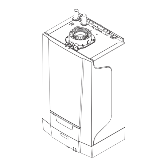
Condensing Central Heating Boiler
Eco Compact Heat
15 - 18 - 24 - 30
These instructions include the Benchmark Commissioning Checklist and should be left with the
user for safe keeping. They must be read in conjunction with the Flue Installation Guide.
Advertisement
Table of Contents


Need help?
Do you have a question about the Eco Compact Heat 15 and is the answer not in the manual?
Questions and answers