Main Combi 24 Installation & Service Instructions Manual
Wall mounted combination boiler gas fired central heating unit
Hide thumbs
Also See for Combi 24:
- User manual (12 pages) ,
- User's manual and important warranty information (12 pages) ,
- Installation & service instructions manual (60 pages)
Table of Contents
Advertisement
Installation & Service Instructions
Combi 24
This is a Wall Mounted Combination Boiler Gas Fired Central Heating Unit.
The boiler meets the requirements of Statutory Instrument " The Boiler (Efficiency)
Regulations 1993 N
o
3083" and is deemed to meet the requirements of Directive
92/42/EEC on the energy efficiency requirements for new hot water boilers fired
with liquid or gaseous fuels:-
Type test for purpose of Regulation 5 certified by:
Notified Body 0051.
Product/Production certified by:
Notified Body 0086.
For use in GB/IE only.
These instructions include the Benchmark Commissioning Checklist and should be
left with the User for safe keeping.
Advertisement
Table of Contents

Related Manuals for Main Combi 24


Summary of Contents for Main Combi 24
- Page 1 Installation & Service Instructions Combi 24 This is a Wall Mounted Combination Boiler Gas Fired Central Heating Unit. The boiler meets the requirements of Statutory Instrument “ The Boiler (Efficiency) Regulations 1993 N 3083” and is deemed to meet the requirements of Directive...
- Page 2 Natural Gas Building Regulations and the Benchmark Commissioning Checklist Main Combi 24 HE G.C.N 47 474 02 Building Regulations (England & Wales) require notification of the installation of a heating appliance to the relevant Local Authority Building Control Department. From 1 April 2005 this can be achieved via a Competent Persons Self Certification Scheme as an option to notifying the Local Authority directly.
- Page 3 INSTALLER NOTIFICATION GUIDELINES Install and Commission this appliance to manufacturer's instructions Complete the Benchmark Checklist Choose Building Regulations Notification Route Competent Person's Building Control Self Certification Scheme If you notify via CORGI Scheme, Contact your relevant Local CORGI will then notify the Authority Building Control relevant Local Authority (LABC) who will arrange...
- Page 4 LEGISLATION IMPORTANT - Installation, Commissioning, Service & Repair Baxi Potterton declare that no substances harmful to health are contained in the appliance or used This appliance must be installed in accordance with the manufacturer’s during appliance manufacture. instructions and the regulations in force. Read the instructions fully before installing or using the appliance.
-
Page 5: Table Of Contents
CONTENTS Section Page Introduction General Layout Appliance Operation Technical Data Dimensions and Fixings System Details Site Requirements Installation Commissioning 10.0 Completion 11.0 Servicing 12.0 Changing Components 13.0 Electrical 14.0 Fault Finding 15.0 Short Parts List Benchmark Checklist... -
Page 6: Introduction
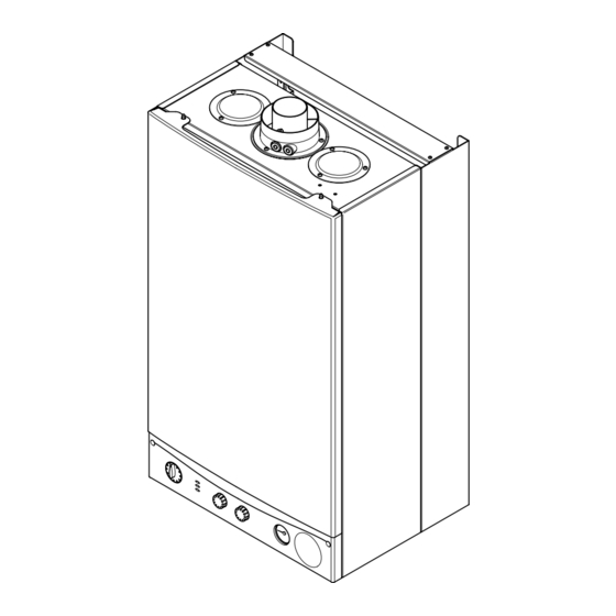
INTRODUCTION Description 1. The Main Combi 24 is a fully automatic gas fired wall mounted combination boiler. It is room sealed and Case Front Panel fan assisted, and will provide central heating and mains fed domestic hot water. 2. The boiler is set to give a maximum output of 24.0 kW. -
Page 7: General Layout
GENERAL LAYOUT Layout Air Pressure Switch Expansion Vessel Burner Manifold Automatic Air Vent DHW Plate Heat Exchanger Circulation Pump Drain Off Point Pressure Relief Valve Optional Integral Timer Position Central Heating System Pressure Gauge Control PCB Control Box 3-Way Valve Assembly Flame Sensing Electrode Spark Electrode Burner... -
Page 8: Appliance Operation
At a pre-determined flow rate the central heating flow switch operates, initiating the ignition sequence. 2. The main burner ignites at low rate, then the gas valve controls the gas rate to maintain the heating temperature measured by the temperature sensor. -
Page 9: Technical Data
TECHNICAL DATA Appliance Type DHW Circuit NO x Class Pressures Appliance Category Flue Terminal Diameter 100mm Max Operating 2H 3+ Dimensions Projection 95mm Min Operating Heat Input C/H & DHW Min Operating Pressure Connections copper tails at 9.8 l/min 26.3 10.6 Gas Supply 22mm... -
Page 10: Dimensions And Fixings
DIMENSIONS AND FIXINGS Dimensions A 780mm B 345mm C 450mm D 107mm Ø Min. E 200mm 360° Orientation F 190mm G 143mm Tube Ø 100mm Fig. 6 Gas Inlet Heating Domestic Hot Cold Water Heating Flow Water Outlet Inlet Return 95mm 65mm 65mm... -
Page 11: System Details
SYSTEM DETAILS Information 1. The Main Combi 24 Combination Boiler is a ‘Water Byelaws Scheme - Approved Product’. To comply with the Water Byelaws your attention is drawn to the following installation requirements and notes (IRN). a) IRN 001 - See text of entry for installation requirements and notes. - Page 12 SYSTEM DETAILS System Filling and Pressurising 1. A filling point connection on the central heating return pipework must be provided to facilitate initial filling and pressurising and also any subsequent water loss replacement/refilling. Double 2. There are connection points on the mains cold water Stop Stop Check...
- Page 13 SYSTEM DETAILS Domestic Hot Water Circuit 1. All DHW circuits, connections, fittings, etc. should Other Tap be fully in accordance with relevant standards, the Outlets Water Supply (water fittings) Regulations and the Water Bylaws (Scotland). Boiler Expansion Vessel 2. Your attention is drawn to: for GB: Guidance G17 to G24 and recommendation R17 to R24 of the Water Regulations Guide.
-
Page 14: Site Requirements
SITE REQUIREMENTS Location 450mm 5mm Min 5mm Min 1. The boiler may be fitted to any suitable wall with the flue passing through an outside wall or roof and discharging to atmosphere in a position permitting satisfactory removal of combustion products and 200mm Min providing an adequate air supply. - Page 15 SITE REQUIREMENTS Ventilation of Compartments 1. Where the appliance is installed in a cupboard or compartment, no air vents are required. The appliance will run sufficiently cool without ventilation. 2. Minimum clearances must be maintained and the compartment should be large enough to house the boiler and any ancillary equipment only.
-
Page 16: System Requirements
SYSTEM REQUIREMENTS Flue 1. the following guidelines indicate the general requirements for siting balanced flue terminals. For GB recommendations are given in BS 5440 Pt 1. For IE recommendations are given in the current edition of I.S. 813 “Domestic Gas Installations”. 2. - Page 17 SITE REQUIREMENTS Flue Dimensions The standard horizontal flue kit allows for flue lengths between 100mm and 1metre from elbow to terminal (Fig. 17). The maximum permissible flue length is: 5 metres. Flue Terminal Trim 1. Once the flue is secure the trim can be fitted if required.
- Page 18 SITE REQUIREMENTS 7.10 Flue Options 1. The Main Combi 24 can be fitted with flue systems as illustrated. 2. The standard flue is suitable only for horizontal applications. 3. Maximum permissible equivalent flue lengths are:- Horizontal 5 metres Vertical 4 metres...
-
Page 19: Installation
INSTALLATION Initial Preparation Fixing Template The gas supply, gas type and pressure must be checked for suitability before connection (see 922.034.1 Section 7.4). 107mm Dia Minimum Aperture For Flue Tube Horizontal Side Flue 107mm diameter minimum Centre Line aperture for flue tube 1. - Page 20 INSTALLATION Fitting The Boiler Wall Plate 1. Lift the boiler using the lower edges. Engage the slots at the top rear of the boiler on the wall plate hooks (Fig. 23). 2. Ensure that the boiler is level and sits against the wall.
- Page 21 INSTALLATION Fitting The Flue HORIZONTAL FLUE Wall Thickness 1. The standard flue is suitable for lengths 100mm minimum to 1m maximum (measured from the edge of the flue elbow outlet). Rear Flue: maximum wall thickness - 900mm Side Flue: maximum wall thickness - 870mm 2.
- Page 22 INSTALLATION Fitting the Flue (Cont) IMPORTANT: If the flue length is greater than 1.5m Elbow the restrictor MUST be removed from the adaptor (Fig. 29). 8. Take one of the rubber seals and position it on the boiler flue adaptor. Engage the flue elbow on the Seal adaptor and pull the sleeve up so that it equally covers the joint (Fig.
- Page 23 INSTALLATION Making The Electrical Connections To connect the mains input cable proceed as Fig. 33 follows:- 1. Slacken the facia panel securing screws and lift the outercase panel so that its securing tabs are clear of the facia. Remove the panel. 2.
-
Page 24: Commissioning
COMMISSIONING Commissioning the Boiler 1. Reference should be made to BS 5449 Section 5 when commissioning the boiler. 2. Open the mains water supply to the boiler. 3. Open all hot water taps to purge the DHW system. 4. Ensure that the filling loop is connected and open, then open the heating flow and return valves on the boiler. - Page 25 COMMISSIONING Checking the Burner Pressure Selector Switch 1. Turn on the gas and electrical supplies to the boiler and ensure that all external controls are calling for heat. 2. Set the temperature controls to maximum and the selector switch to the Off position (Fig. 42). Reset Burner On Flame Failure...
-
Page 26: Completion
10.0 COMPLETION 10.1 Completion 1. Hinge the facia panel upwards and engage the securing screws. Refit the case front panel and tighten Case Front Panel the screws (Fig. 45). 2. Instruct the user in the operation of the boiler and system, explaining the operational sequence. -
Page 27: Servicing
11.0 SERVICING Case Front Panel 11 .1 Annual Servicing 1. For reasons of safety and economy, it is recommended that the boiler is serviced annually. Servicing must be performed by a competent person. 2. After servicing, complete the relevant Service Interval record section of the Benchmark Commissioning Checklist at the rear of this publication. - Page 28 11.0 SERVICING 11.1 Annual Servicing (Cont) Baffle 10. Remove the spring clips retaining the air box side Spring Clip baffle plates. Disengage the tabs on the baffles from the slots in the fan hood (Fig. 52). 11. Undo the screws securing the fan hood assembly to the appliance back panel, and draw the fan and hood assembly forwards (Fig.
-
Page 29: Changing Components
12.0 CHANGING COMPONENTS IMPORTANT: When changing components ensure Pressure that both the gas and electrical supplies to the Switch boiler are isolated before any work is started. When the component has been changed turn the selector switch fully anticlockwise against the Fig. - Page 30 12.0 CHANGING COMPONENTS 12.3 Heat Exchanger (Fig. 62) 1. Note the positions of the two sensing tubes on the outlet elbow and three wires on the fan motor and remove them (Figs. 58 to 61). 2. Slacken the screws on the outlet sealing collar. Ease the collar upwards as far as possible.
- Page 31 12.0 CHANGING COMPONENTS Injector Inlet Elbow 12.5 Injectors (Fig. 64) Manifold 1. Remove the burner as described in Section 12.4. Fig. 64 2. Undo the screws securing the injector manifold to the inlet elbow and remove the manifold. Gasket 3. Unscrew and replace injectors as required and examine the sealing gasket, replacing as necessary.
- Page 32 12.0 CHANGING COMPONENTS 12.8 Gas Valve (Fig. 66) 1. Undo the nut on the gas feed pipe under the boiler. 2. Completely undo the securing screws and hinge the facia panel down. Electrode 3. Disconnect the earth wire and pressure sensing pipe Lead Earth from the valve.
- Page 33 12.0 CHANGING COMPONENTS 12.11 Pump - Head Only (Figs. 68 & 69) 1. Drain the primary circuit and remove the socket head screws securing the pump head to the body and draw the head away. 2. Undo the screw on the pump wiring cover and remove the cover.
- Page 34 12.0 CHANGING COMPONENTS 12.14 Pressure Gauge 1. Drain the primary circuit and undo the nut on the pressure gauge capillary (Fig. 71). Fig. 71 2. Remove the timer cover and ease the timer wiring aside. Undo the screws securing the gauge retaining bracket (Fig.
- Page 35 12.0 CHANGING COMPONENTS 12.17 Pressure Relief Valve (Fig. 78) 1. Drain the primary circuit. 2. Disconnect the discharge pipe from the valve. Using a suitable hexagon key undo the grub screw sufficiently to release the valve. 3. Note the orientation of the valve, rotate it and withdraw it from the manifold.
- Page 36 12.0 CHANGING COMPONENTS 12.20 Plate Heat Exchanger (Fig. 81) Plate Heat Exchanger 1. Drain the primary circuit. Fig. 81 2. While supporting the heat exchanger undo the screws securing it to the brass manifolds. 3. Withdraw the heat exchanger upwards and to the left of the gas valve, taking care not to damage any wires or controls.
- Page 37 12.0 CHANGING COMPONENTS Central Heating 12.21 Diverter Valve Assembly (Cont) Microswitch & Pressure Differential Bracket Valve CH Pressure Differential Valve (Fig. 84) Sensing Pipe 1. Remove the DHW pressure differential valve as described above. By-pass 2. From the brass diverter manifold undo the nut on Pipe Diaphragm the heating flow pipe.
-
Page 38: Electrical
13.0 ELECTRICAL Pump Mains Input Link On/Off/Reset Selector Switch Fuse Temperature Sensor Hydraulic Differential Pressure Switch Optional Timers Gas Valve Control PCB Overheat Thermostat 3-Way Valve Air Pressure Microswitch Switch Flame - green - brown Sensing - black - green / yellow Electrode - white - blue... -
Page 39: Fault Finding
14.0 FAULT FINDING Carry out initial fault finding checks 1. Check that gas, water and electrical supplies are available at the boiler. Electrical supply = 230V ~ 50 Hz. CH water system pressurised to 0.5 bar when the boiler is cold. The preferred minimum gas pressure is 19.5mbar (natural gas), 27mbar (butane) or 36mbar (propane). - Page 40 14.0 FAULT FINDING Domestic Hot Water - Follow operational sequence Turn selector to Replace diaphragm Go to section ‘A’ neon illuminated Is mains water DHW flow valve filter and differential diaphragm damaged assembly clean? Turn thermostat to DHW flow rate more than DHW flow valve rod max.
- Page 41 14.0 FAULT FINDING Fault Finding Solutions Sections A to E Is there 230V at: Main terminals L and N Check electrical supply Main terminal fuse Replace fuse neon Replace PCB illuminated Selector terminals a & b Check wiring and a & 3. PCB - M1 Replace selector connector terminals 9 &...
- Page 42 (Use an instrument with average function for this measure) Replace PCB 30 ÷ 230 mA DC (45 ÷ 310 mA DC LPG) Check and correct if necessary 230V at Main PCB - M4 Replace PCB 1. Ignition electrode and lead connector across terminals 2. Electrode connection 37 &...
- Page 43 14.0 FAULT FINDING Ensure that mains input terminal L is Live (230V) and N is Neutral (0V) Check and correct if necessary 1. Flame sensing electrode and lead connections 2. Electrode position Replace PCB Flame current should be 1 µA approx. Replace flame sensing electrode Overheat thermostat operated Allow to cool.
-
Page 44: Short Parts List
15.0 SHORT PARTS LIST Short Parts List Key G.C. Description Manufacturers Part No. E66 383 Fan 248001 393-497 Pressure Switch 247380 E66 393 Heat Exchanger 248016 E66 398 Burner 248029 E66 402 Injector - 1.28 NG 248210 Injector - 0.77 LPG 248211 E66 408 Electrode Lead 248037... - Page 45 16.0 NOTES...
-
Page 46: Benchmark Checklist
5 1 1 5 8 0 7 BENCHMARK No. GAS BOILER COMMISSIONING CHECKLIST C O L L E C T I V E M A R K BOILER SERIAL No. NOTIFICATION No. CONTROLS To comply with the Building Regulations, each section must have a tick in one or other of the boxes TIME &... -
Page 47: Service Interval Record
SERVICE INTERVAL RECORD It is recommended that your heating system is serviced regularly and that you complete the appropriate Service Interval Record Below. Service Provider. Before completing the appropriate Service Interval Record below, please ensure you have carried out the service as described in the boiler manufacturer’s instructions. - Page 48 - Iss. 2 Publication No. 5115807 (05/2005) General Enquiries (GB) 08706 060 780 Tel. Technical (GB) 08706 049 049 Tel. Service (GB) 08701 655 644 Tel. 01926 410 006 Fax. Literature Request (GB) 08706 060 623 Tel. Technical (IE) 1850 560570 Tel.
Need help?
Do you have a question about the Combi 24 and is the answer not in the manual?
Questions and answers