Table of Contents
Advertisement
Quick Links
Advertisement
Table of Contents

Related Manuals for Vent-Axia Lo-Carbon VA150 Series


Summary of Contents for Vent-Axia Lo-Carbon VA150 Series
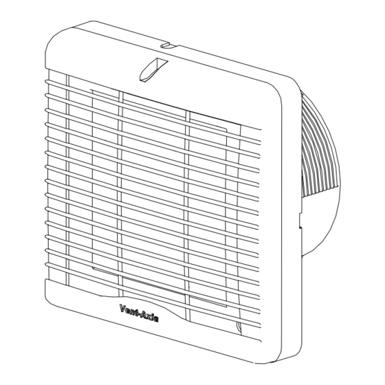
- Page 1 VA150 Lo-Carbon RANGE Axial Kitchen & Utility Room Fans Installation and wiring Instructions Stock Ref.No Lo-Carbon VA150P 459123A Lo-Carbon VA150T 459124A Lo-Carbon VA150HP 459125A 220-240V~50Hz READ IN CONJUNCTION WITH ILLUSTRATIONS PLEASE SAVE THESE INSTRUCTIONS...
-
Page 3: Safety And Guidance Notes
C. Ensure that the mains supply (Voltage, Frequency, and Phase) complies with the rating label. D. The Fan should only be used in conjunction with the appropriate Vent-Axia products. E. It is recommended that the connection to the fan connecter terminals is made with flexible cable. -
Page 4: Wall Mounting
INSTALLATION. PANEL MOUNTING 1. Cut a 152mm hole through the panel, also suitable for existing holes up to 185mm. 2. Remove the Indoor Grille [A]. Loosen the screw (top middle) of the Grille, to release front grille gently lever the Grille downwards away from the Inner Cover [B]. -
Page 5: Timer Adjustment
WIRING. WARNING: THE FAN AND ANY ANCILLARY CONTROL EQUIPMENT MUST BE ISOLATED FROM THE POWER SUPPLY DURING THE INSTALLATION / OR MAINTENANCE. 1. Select and follow the appropriate wiring diagram (Fig. 2-4). 2. Check all connections have been made correctly and ensure all terminal connections and cable clamps are securely fastened. -
Page 6: Servicing And Maintenance
Fig. 4. Lo-Carbon U/KHP (45 91 25A) Humidity Controlled Model. Select the wiring configuration required for the Utility or Kitchen. 1 Phase Supply (220-240V 50Hz). FUSE Switched Fused Spur Humidity Adjuster. 8V = Low Speed for a Utility Room 12V = High Speed for a Kitchen Humidity Set-Point Adjustment. - Page 8 Vent-Axia guarantees its products for two years from date of purchase against faulty material or workmanship. In the event of any part being found to be defective, the product will be repaired, or at the Company’s option replaced, without charge, provided that the product:- ...