Advertisement
Quick Links
Advertisement

Related Manuals for Vent-Axia PoziDry Pro


Summary of Contents for Vent-Axia PoziDry Pro
- Page 1 PoziDry Pro Positive Input Ventilation Unit Installation and Wiring Instructions Stock Ref. N° 476310 – PoziDry Pro 476311 – PoziDry Pro with Heater 476312 – PoziDry Pro FD 220-240V~50Hz PLEASE READ INSTRUCTIONS IN CONJUNCTION WITH THE ILLUSTRATIONS. PLEASE SAVE THESE INSTRUCTIONS...
- Page 2 Installation and Wiring Instructions for the Lo-Carbon PoziDry Pro Positive Ventilation Unit. SAFETY AND GUIDANCE NOTES IMPORTANT: READ THESE INSTRUCTIONS BEFORE COMMENCING THE INSTALLATION DO NOT install this product in areas where the following may be present or occur: 1.1. Excessive oil or a grease laden atmosphere.
-
Page 3: Introductory Notes
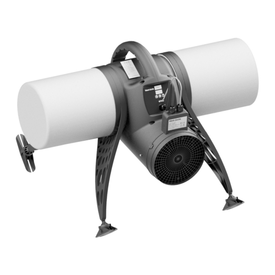
A. INTRODUCTORY NOTES The Vent Axia Lo-Carbon PoziDry Pro is a positive input ventilation unit, designed to be installed in the loft of a dwelling to continually supply filtered fresh air into the building. The system consists of a fan unit, a heater unit (for heater models) and a diffuser (for diffuser models) with a short length of flexible ducting. - Page 4 The fan unit can be floor mounted or hung from a roof beam. Hanging method: The Lo-Carbon PoziDry Pro can be hung from a roof beam (Fig. 2). Fix the screw eye to a convenient roof beam. Use the cord provided to loop through the eye and around the handle on the unit, there are various notches for the cord to run through, tie the two ends together using a suitable knot such as an over hand or fisherman’s knot.
- Page 5 Floor mounting: Attach the mounting legs to the unit, two per side. Find a suitable location to fix the unit near to where the diffuser is to be located. Ensure that the route for the flexible ducting has gentle bends and that the duct cannot be crushed Fig.3. See Diffuser Grille Fitment section below for more information.
- Page 6 IMPORTANT – SMOKE DETECTORS: The diffuser should not be situated within 1m of a smoke detector, however if this is not possible the Lo-Carbon PoziDry Pro has provisions to blank off the airflow for up to two quadrants of the diffuser. Two blanking plates are provided; these should be pushed on to the support struts inside the diffuser as required.
- Page 7 TWIN SPIGOT OPTION (PIV twin spigot kit Ref:- 449071) Ensure that the adjustable diffuser supplied with the kit is installed nearer to the PoziDry Pro unit than the diffuser supplied with the unit (Fig.7). This allows both flows to be balanced.
- Page 8 Fig. 11. The Lo-Carbon PoziDry Pro is provided with G4 filters which are suitable for removing airborne contaminants such as pollen and dust. Where higher grade filtration is required, optional F7 filters can be used. These filters are effective at removing finer particles such as particulate emissions from diesel engines. In urban areas close to main roads F7 filters are advisable in order to ensure the supply air is clear of these particles which are potentially harmful to health.
- Page 9 CONTROL EQUIPMENT MUST BE ISOLATED FROM THE POWER SUPPLY DURING THE INSTALLATION / OR MAINTENANCE. The Lo-Carbon PoziDry Pro is designed for operation from a single-phase alternating current source (220-240V AC). A 2m integral mains flying lead is connected to the unit for connection to a spur. It should be capable of disconnecting all poles, having a contact separation of at least 3mm.
- Page 10 Boost Switch Link Connector option (Ref:- 411150) IMPORTANT: Do not connect mains or any other device to the remote boost cable. It is only intended to be linked via a remote volt free switch to activate the boost function. 1) Connect the boost cable (supplied with 411150) to the connector under the display (on the fan).
-
Page 11: Start-Up Sequence
D. SETUP START UP SEQUENCE When the unit is switched on it will first run through a period of system checks. During this time the display will show various system parameters before the fan motor starts. After 10 seconds the product will be ready for commissioning COMMISSIONING Accessing the Commissioning Menu... - Page 12 Speed Settings The Lo-Carbon PoziDry Pro has two speed settings, ‘Trickle’ and ‘Energy Recovery’. ‘Trickle’ speed is automatically selected when the ambient loft temperature is below the Trickle Speed Temperature Threshold setting. Default setting is 18°C. ‘Energy Recovery’ is automatically selected when the ambient loft temperature is between the Trickle Speed Temperature (default is 18°C) and Temperature Limit setting...
- Page 13 Trickle Speed Temperature Threshold The temperature the fan will switch from Energy Recovery Mode to Trickle mode. Usually this would be set to around 18-20°C to be slightly cooler than the normal heating thermostat temperature. Default is 18°C. Temperature Limit This is the maximum temperature the fan will run until going into standby.
-
Page 14: Servicing And Maintenance
The fan motor uses sealed ball bearings, and does not require further lubrication. Apart from filter change the Lo-Carbon PoziDry Pro contains no user serviceable parts. Filter: Under normal conditions; i.e. away from main roads and industrial areas, it is recommended that the filter is checked annually and cleaned or replaced as necessary. - Page 15 PRODUCT FICHE For Residential Ventilation Units (Complying Commission Delegated Regulation (EU) No 1254/2014) Name: Vent‐Axia Vent‐Axia Vent‐Axia Lo‐Carbon PoziDry Pro ‐ Lo‐Carbon PoziDry Pro ‐ Lo‐Carbon PoziDry Pro ‐ Model ID (Stock Ref.) : 476310 476311 476312 SEC Class B B B SEC Value ('Average') 28.30 28.30 28.30 SEC Value ('Warm') 12.80 12.80 12.80 SEC Value ('Cold') 55.36 55.36 55.36 Label Required? (Yes/No=Out of scope) ...
- Page 16 Vent-Axia Guarantees this product for 5 years from date of purchase against faulty material or workmanship. In the event of any part being found to be defective, the product will be repaired, or at the Company’s option replaced, without charge, provided that the product:- ...
Need help?
Do you have a question about the PoziDry Pro and is the answer not in the manual?
Questions and answers