
Related Manuals for Nautel NV7.5


Summary of Contents for Nautel NV7.5
- Page 1 NV10/NV7.5 Transmitter Operations and Maintenance Manual Document:NHB-NV7.5-NV10-OPS-3.4 Issue: 3.4 2016-08-03 Status: Standard...
- Page 3 The comparisons and other information provided in this document have been prepared in good faith based on publicly available information. The reader is encouraged to consult the respective manufacturer's most recent published data for verification. © Copyright 2012 NAUTEL. All rights reserved.
-
Page 5: Table Of Contents
NV10/NV7.5 Operations and Maintenance Manual Table of contents Contents Release control record About this manual About Safety xiii Electrical Hazards 1-xiii Lightning Hazards 1-xiv RF Hazards 1-xiv Toxic Hazards 1-xiv Other Hazards 1-xiv Safety Precautions Personal Safety 1-xv Site Safety... - Page 6 NV10/NV7.5 Operations and Maintenance Manual Table of contents Viewing real-time meters 2-45 Presets - editing operational settings 2-50 Viewing transmitter status 2-66 Factory Settings 2-69 System Settings 2-78 User accounts 2-88 Changeover page 2-92 User settings 2-94 Remote I/O page...
-
Page 7: Release Control Record
Section 3: expanded air filter descriptions to include M7, MERV 7 filters as suitable replacements 2013-10-01 Added nautel Phone Home to user Settings 2014-12-10 Section 2: updated to support software release 4.2.7 or later, changed exciter TCXO screen to show dual exciter option. - Page 8 NV10/NV7.5 Operations and Maintenance Manual Page viii Issue 3.4 2016-08-03...
-
Page 9: About This Manual
NV10/NV7.5 Operations and Maintenance Manual About this manual This manual provides technical information needed when operating, maintaining and troubleshooting an NV10/NV7.5 transmitter. This manual is intended for use by transmitter operators and field technicians. Using this manual If you are responsible for configuring or operating a transmitter, see Section 2, “Operating the... - Page 10 Tip: When you have completed a task or a step, put a checkmark beside the step number. Technical support Nautel offers technical support to customers over the Internet and by telephone. Nautel’s customer support team will answer your questions and work with you to identify and resolve problems.
- Page 11 The Nautel website provides useful resources to keep you up to date on your NV10/NV7.5. Nautel User Group (NUG) The website includes a special section that customers can log into in order to access the Nautel customer newsletter, product manuals, frequently asked questions (FAQ), information sheets, and information about field upgrades.
- Page 12 NV10/NV7.5 Operations and Maintenance Manual Page xii Issue 3.4 2016-08-03...
-
Page 13: About Safety
NV10/NV7.5 Operations and Maintenance Manual About Safety All Nautel transmitters are designed to meet the requirements of EN60215, Safety Requirements for Radio Transmitters. The philosophy of EN60215 is that the removal of any cover or panel that can only be opened using a tool is a maintenance activity, and that any person performing a maintenance activity is expected to be trained for that activity. -
Page 14: Lightning Hazards
NV10/NV7.5 Operations and Maintenance Manual Use only a non-contact voltage probe or a safety voltmeter (available from vendors such as Fluke, Ideal, and Teagam). Use a proper lockout procedure to ensure that another worker cannot accidentally reapply power while you are performing maintenance on any part of the transmitter or site. -
Page 15: Safety Precautions
Personnel must be familiar with the transmitter, so that they can avoid physical danger, and be aware of hazards to themselves and the equipment. Nautel offers a number of training courses covering the basic fundamentals of RF systems and transmitters, and the operation and maintenance of the transmitter. For more information about available courses and schedules, go to the Nautel website at http://www.nautel.com/... - Page 16 • Operation of safety interlocks (if installed) First Aid Nautel does not offer first aid training, since the hazards associated with high voltage and RF energy are not specific to the transmitter. However, the customer should provide first aid training to all personnel who have access to the transmitter site. First aid training should include CPR, care of burns, artificial respiration, and defibrillation if specific equipment is available on-site.
- Page 17 NV10/NV7.5 Operations and Maintenance Manual Marking Hazards Place warning signs close to any hazardous areas or systems (e.g., the feedline or the antenna system). Make the signs large enough that they cannot be missed. Provide signage in all languages used in the region. These signs are intended not only for authorized personnel, but also for emergency responders or accidental trespassers.
- Page 18 (and to protect the rest of your site equipment and your personnel). For detailed information about lightning protection, see the Nautel Site Preparation Manual, available from your Nautel sales agent, or online from the Nautel website.
- Page 19 NV10/NV7.5 Operations and Maintenance Manual Physical Protection Consider physical hazards to equipment at your site, including the transmitter. Ensure that equipment is protected from weather (e.g., rain or flooding), even during extreme weather events. Place equipment so that it is not in the path of swinging doors or high-traffic areas. Do not allow wheeled items like office chairs or tables with wheels in the transmitter room, as these may damage equipment if accidentally pushed or knocked over.
- Page 20 NV10/NV7.5 Operations and Maintenance Manual Page xx Issue 3.4 2016-08-03...
-
Page 21: Description
Some descriptions in this section refer to electrical schematics (SD-#s) . These are located in Section 5 of the NV10/NV7.5 Troubleshooting Manual. Redundancy The NV10/NV7.5 features redundancy in all key systems: • RF power modules • Exciters • Cooling fans •... - Page 22 NV10/NV7.5 Operations and Maintenance Manual Description Ac-dc power stage See electrical schematics SD-1 ( A , B or C ), SD-2 and SD-3 . The ac-dc power stage converts the ac power source to a positive dc voltage (PA volts) for the transmitter's intermediate (IPA) and RF power amplifiers.
- Page 23 NV10/NV7.5 Operations and Maintenance Manual Description LVPS modules See Figure SD-1 ( A , B or C ). LVPS modules A (U3) and B (U4) convert the ac input voltage to the regulated low voltage dc supplies. The +5 V, +15 V and -15 V regulated outputs of the supplies are ORed together at the control/interface PWB (A1) and applied throughout the transmitter.
-
Page 24: Using The Aui
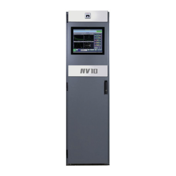
NV10/NV7.5 Operations and Maintenance Manual Description U5 is a 17-inch, colour LCD screen that is mounted on the front of the transmitter. It provides an advanced user interface (AUI) for the transmitter. The AUI can be controlled by touch screen and is also available as a flash graphic on any web-interfaced PC or handheld device via the internal NV web server. - Page 25 Exciters A (A3) and B (A4) are the RF drive sources for the transmitter. They accept the external audio program and/or IBOC information (see the NV10/NV7.5 Installation Manual for details on various program input types). The exciters’ main/standby operation is controlled locally using the AUI, or remotely.
- Page 26 Each of the four RF power modules provides up to 2750 W (for NV10) or 2062.5 W (for NV7.5) of RF output power and is comprised of an IPA power amplifier PWB, eight power amplifier PWBs, power module interface PWB, combiner PWB, splitter PWB and six cooling fans.
- Page 27 RF monitor PWB A3 provides a nominal 2.2 V (NV10) or 1.8 V (NV7.5) rms [at 10 kW (NV10) or 7.5 kW (NV7.5) signal at A3J1 for use with a modulation monitor or spectrum analyzer. RF sample PWBs A4 and A5 provide similar samples at A4J1 and A5J1.
- Page 28 NV10/NV7.5 Operations and Maintenance Manual Description Page 1-8 Issue 3.4 2016-08-03...
- Page 29 NV10/NV7.5 Operations and Maintenance Manual Figure 1.2: NV Series Transmitter Block Diagram 10KW POWER BLOCK MODULE A PWR SUPPLY IPA PWR SUPPLY PWR SUPPLY 3 PHASE AC POWER 400VAC LV PWR LV PWR SUPPLY A SUPPLY LV PWR SPLITTER COMBINER...
- Page 30 NV10/NV7.5 Operations and Maintenance Manual Figure 1.3: NVE50 Exciter Block Diagram EXCITER PWB EXTERNAL 10MHz REFERENCE TOSLINK OPTICAL ASRC 2 x AES/EBU POWER AMPLIFIER SCA GENERATOR VSWR PROTECTION TCXO OR COMPOSITE SCA PLL & VCSO OCXO TEMP SENSE BIAS BIAS...
- Page 31 NV10/NV7.5 Operations and Maintenance Manual Figure 1.4: RF Power Module Block Diagram 4-WAY 4-WAY OUTPUT SPLITTER COMBINER 4-WAY 4-WAY RF DRIVE SPLITTER COMBINER IPA PWR SUPPLY PWR SUPPLY 1 PWR SUPPLY 2 B2060005 VB Issue 3.4 2016-08-03 Page 1-11...
- Page 32 NV10/NV7.5 Operations and Maintenance Manual Issue 3.4 2016-08-03 Page 1-12...
-
Page 33: Viewing Real-Time Meters
NV10/NV7.5 Operations and Maintenance Manual Operating the transmitter Section 2: Operating the transmitter This section provides information about operating the NV10/NV7.5 transmitter: • Using the AUI - see page 2-2 • Home page - see page 2-15 • Menu page - describing transmitter operations - see page 2-16 •... - Page 34 NV10/NV7.5 Operations and Maintenance Manual Operating the transmitter Using the AUI The NV40/30 has an advanced user interface (AUI) that is displayed on a 17-inch, colour LCD screen mounted on the front of the control cabinet (Figure 2.1). The AUI is controlled via touch screen that you can also access using a PC and a web browser.
-
Page 35: Viewing Transmitter Status
NV10/NV7.5 Operations and Maintenance Manual Operating the transmitter Information is displayed in a series of pages (screens) that serve specific transmitter functions. The AUI has the following configurable displays: • Login Page (see Logging into the AUI on page 2-3) •... - Page 36 • In the User field, enter the username. Default is “Nautel”. • In the Password field, enter the password. Default is blank. Note: The Nautel AUI is factory configured with a default login username and password. Nautel recommends that you change the password to improve overall system security. See Changing the password on page 2-90.
- Page 37 • In the Language field, press the down-arrow to review a drop-down menu displaying the available language options, and select one. • In the User field, enter the username. Default is “Nautel”. • In the Password field, enter the password. Default is blank.
- Page 38 NV10/NV7.5 Operations and Maintenance Manual Operating the transmitter Page 2-6 Issue 3.4 2016-08-03...
- Page 39 Set User Type/Permissions page 2-89 Adding An Account page 2-89 (Return to) HOME Menu Home page 2-15 page 2-16 User Accounts Editing An Existing Account page 2-89 page 2-14 page 2-88 Changing The Password page 2-90 Setting Autologin page 2-90 General page 2-53 Presets...
- Page 40 Issue 3.4 2016-08-03 Page 2-7 (Page 2-8 Blank)
- Page 41 NV10/NV7.5 Operations and Maintenance Manual Operating the transmitter Figure 2.3: Remote AUI Login Menu IP address and login messages AUI software version Describing the AUI layout The AUI begins with the Home page and all further navigation will start from this screen (see Figure 2.4 on page...
- Page 42 NV10/NV7.5 Operations and Maintenance Manual Operating the transmitter List of AUI pages Table 2.1 defines the available AUI pages. Table 2.1: AUI Pages AUI Page Function See Page Home View meters, tool menu panels, choose options and page 2-15 navigate to other pages.
- Page 43 Window The top banner is permanent on all AUI pages and includes: • Nautel Logo: From any AUI page, press the displayed logo to reload the AUI and prompt for a login. Press this if your local AUI stops responding.
- Page 44 NV10/NV7.5 Operations and Maintenance Manual Operating the transmitter • Exciter : Displays the active exciter and the peak (red) FM modulation value. Press in the Active Exciter field to shortcut to the Changeover page. The active exciter is dis- played in the top, right corner (see Figure 2.4).
- Page 45 NV10/NV7.5 Operations and Maintenance Manual Operating the transmitter • Reset: Press to reset protection circuits and restore any RF power modules (and associ- ated power supplies) that were inhibited, but are now alarm-free. • Change User/Log Out: Press to display a login menu. Enter your username and pass- word, then press Done.
- Page 46 NV10/NV7.5 Operations and Maintenance Manual Operating the transmitter The displays between the top and bottom menus, contains user selected pages. These pages provide access to a variety of AUI functions such as transmitter status and hardware settings. The following paragraphs describe how to use these pages.
- Page 47 NV10/NV7.5 Operations and Maintenance Manual Operating the transmitter Home page The Home page is the first screen to appear when you login into the AUI. You can return to page, from any screen, by pressing on the logo (upper left corner) or by pressing Home Menu >...
- Page 48 NV10/NV7.5 Operations and Maintenance Manual Operating the transmitter Menu page - describing transmitter operations From the page, press the Menu button to view the Menu page (see Figure 2.7). The Home Menu page displays icons that link to pages that control various transmitter operations.
- Page 49 NV10/NV7.5 Operations and Maintenance Manual Operating the transmitter Press User Accounts to access a page that displays a list of users with access to the AUI and, depending on permission level, allows editing of user accounts (see User accounts on page 2- 88).
- Page 50 NV10/NV7.5 Operations and Maintenance Manual Operating the transmitter Figure 2.8: Log page Page number of displayed page first page page-by-page row-by-row row-by-row page-by-page last page Navigate through the table using these arrows Viewing event logs page displays a “read only” chronological table of log events under the following...
- Page 51 NV10/NV7.5 Operations and Maintenance Manual Operating the transmitter Figure 2.9: Alarm Severity = low (RF output not affected) = medium (RF output may be reduced) = high (RF output may be inhibited) • Time of Event - identifies the day-of-the-week, date and time of the alarm event.
- Page 52 NV10/NV7.5 Operations and Maintenance Manual Operating the transmitter Understanding the log manager window The Log Manager window contains the functions that edit the logs listed in the page. Logs Press the Log Manager button to open a configurable window with the following display...
- Page 53 NV10/NV7.5 Operations and Maintenance Manual Operating the transmitter Filtering logs You can filter transmitter events based on their device or date by clicking the Filter Logs button in the Log Manager (see Figure 2.10). Select a Device by pressing the Select a Device button to reveal the following event monitoring options in a drop-down menu: –...
- Page 54 NV10/NV7.5 Operations and Maintenance Manual Operating the transmitter Copying logs You can create a copy of all the logs in the selected list while remotely logged into AUI (these are copied to the remote user’s computer clipboard) by clicking on the Copy Logs button in the...
- Page 55 NV10/NV7.5 Operations and Maintenance Manual Operating the transmitter Figure 2.12: Log Manager - Deleting Logs Month Year Hours Minutes Viewing log statistics Users can view statistical information on the events being displayed by clicking on the Statistics button in the Log Manager (see Figure 2.13 on page...
- Page 56 NV10/NV7.5 Operations and Maintenance Manual Operating the transmitter – Earliest - refers to the first time of an alarm occurrence. – Latest - refers to the last time of an alarm occurrence. If an alarm has only one occurrence (i.e., # Events column is 1), then the time in the “...
- Page 57 NV10/NV7.5 Operations and Maintenance Manual Operating the transmitter Viewing the legend The Legend tab is different from the other tabs. Press the Legend tab to display a window describing the meaning of the symbols that appear in the State and Severity columns of the...
- Page 58 NV10/NV7.5 Operations and Maintenance Manual Operating the transmitter Viewing tool menu panels The center area of the page screen displays up to 4 panels of instrument information. Home Users can choose which panels to display from 9 possible information panels (see Figure 2.15).
- Page 59 NV10/NV7.5 Operations and Maintenance Manual Operating the transmitter To view the instrument panel options , close an existing panel by pressing (upper-right corner) and then press the icon in the blank space to open the . Select an icon to Tool Menu display that panel.
- Page 60 NV10/NV7.5 Operations and Maintenance Manual Operating the transmitter Describing instrument panel options The following table describes instrument panel options: Table 2.2: Tool Menu Panels Tool Description Reference Spectrum Displays a spectrum analyzer, capable of monitoring page 2-32 the transmitter’s RF output spectrum and various RF sections of the exciter.
- Page 61 NV10/NV7.5 Operations and Maintenance Manual Operating the transmitter Viewing instrument panels Each instrument panel has a menu bar that may be different from other panels (see Figure 2.16). Figure 2.16: Instrument Panel Menus Backward one step Forward one step Maximize / Minimize...
- Page 62 NV10/NV7.5 Operations and Maintenance Manual Operating the transmitter • To enlarge/reduce the instrument panel, use the maximize/minimize buttons. Some instrument displays show more information when maximized. – Most panels can be maximized to fill the whole screen, e.g., EQ Impulse Response (see Figure 2.18 on page...
- Page 63 NV10/NV7.5 Operations and Maintenance Manual Operating the transmitter Figure 2.18: Instrument Panel - Expansion Example 1 Maximize/Minimize buttons Figure 2.19: Instrument Panel - Expansion Example 2 Maximize/Minimize buttons Issue 3.4 2016-08-03 Page 2-31...
- Page 64 If these spurious emissions are observed on the spectrum analyzer, Nautel recommends that a calibrated, external spectrum analyzer be used to verify the presence of spurs.
- Page 65 NV10/NV7.5 Operations and Maintenance Manual Operating the transmitter Figure 2.20: Spectrum Analyzer Peak Cog Issue 3.4 2016-08-03 Page 2-33...
- Page 66 NV10/NV7.5 Operations and Maintenance Manual Operating the transmitter Use the left and right buttons to make fine adjustments. Use the maximize or minimize buttons as required. Use the “peak” button to place the cursor on the next successive peak (moving left to right) in the spectrum.
- Page 67 NV10/NV7.5 Operations and Maintenance Manual Operating the transmitter Figure 2.21: Spectrum Settings Equalizer screens The NV10/NV7.5’s exciter includes a fixed equalizer to optimize audio performance. There are three EQ instrument panels available in the Tool Menu - EQ Frequency (see Figure 2.22), EQ Impulse Response (see Figure 2.23 on page...
- Page 68 NV10/NV7.5 Operations and Maintenance Manual Operating the transmitter Figure 2.22: EQ Frequency Response EQ frequency response Figure 2.22. This panel displays the frequency response of the active exciter’s EQ filter. The panel displays the gain of the filter with respect to the magnitude and frequency of the modulating signal.
- Page 69 NV10/NV7.5 Operations and Maintenance Manual Operating the transmitter Figure 2.23: EQ Impulse Response EQ impulse response Figure 2.23. This panel displays the impulse response of the modulator’s EQ filter in the time domain. This is a static display tool so the screen image is not fluid and will not change.
- Page 70 NV10/NV7.5 Operations and Maintenance Manual Operating the transmitter Figure 2.24: EQ Filter Delay EQ filter delay Figure 2.24. This panel displays the delay of the modulator’s EQ filter across its bandwidth. Touch on the panel to display a cursor in the approximate area. The cursor position (delay and frequency) is noted in the upper, right-hand corner of the panel.
- Page 71 NV10/NV7.5 Operations and Maintenance Manual Operating the transmitter AM-AM and AM-PM correction screens When the transmitter is operating with digital carriers, the exciter linearizes the transmitter’s RF drive signal by performing adaptive pre-correction. There are two correction parameters - AM-AM Correction (see Figure 2.25) and AM-PM Correction (see...
- Page 72 NV10/NV7.5 Operations and Maintenance Manual Operating the transmitter Touch on the panel to display a cursor in the approximate area. The cursor position (Gain and LUT index) is noted in the upper, right-hand corner of the panel. Touch in other areas of this instrument panel to provide a coarse adjustment of the cursor position.
- Page 73 NV10/NV7.5 Operations and Maintenance Manual Operating the transmitter Figure 2.27: Signal Constellation Signal constellation Figure 2.27. The exciter constantly measures the transmitter signal and performs basic demodulation of the digital carriers. The Signal Constellation panel displays the phase and amplitude of the symbols being modulated within an OFDM sub-carrier as dots on a cartesian graph.
- Page 74 NV10/NV7.5 Operations and Maintenance Manual Operating the transmitter Use the scroll bar to select a higher or lower sub-carrier for viewing. Some sub-carriers are for timing and synchronization. Others are modulated with data/content. Use the maximize or minimize buttons as required.
- Page 75 NV10/NV7.5 Operations and Maintenance Manual Operating the transmitter The plot consists of a group of sequential samples to allow signal analysis. In L and R mode, the L+R portion of the signal tends to dominate the plot, resulting in the majority of samples appearing in the lower, left and upper, right quadrants.
- Page 76 NV10/NV7.5 Operations and Maintenance Manual Operating the transmitter Touch on the panel to display a cursor in the approximate area. The cursor position (power gain and probability index) is noted in the upper, right-hand corner of the panel. Touch in other areas of this instrument panel to provide a coarse adjustment of the cursor position.
- Page 77 NV10/NV7.5 Operations and Maintenance Manual Operating the transmitter Viewing real-time meters The AUI can be used to display metered parameters on the page (see Figure 2.30), if Home selected individually from the page or saved in a meter list layout and set to Meters List View default.
- Page 78 NV10/NV7.5 Operations and Maintenance Manual Operating the transmitter Describing the meter display The meters displayed in the AUI represent the active meters selected for display. Each meter is a colour-coded bar with minimum and maximum values (see Figure 2.30). The current value for a meter is indicated by an arrow on the colour-coded bar, as well as a numeric value below the meter.
- Page 79 NV10/NV7.5 Operations and Maintenance Manual Operating the transmitter • A parameter value in the yellow section (as applicable) of a meter bar indicates the parameter is still within an operational range, but is approaching design limitations. • A parameter value in the red section of a meter bar indicates the parameter is outside normal operating conditions.
- Page 80 NV10/NV7.5 Operations and Maintenance Manual Operating the transmitter Identifying meter information on a specific sub-device Open the Meters List View window and select one of the desired transmitter sub-devices. – Controller – Exciter A – Exciter B – RF Modules - Multiple modules supported Under Transmitter Layout , press the information button (i) beside a device type.
- Page 81 NV10/NV7.5 Operations and Maintenance Manual Operating the transmitter Saving a meter list Note: Meter lists are associated with user accounts. Lists saved in this screen are only displayed in the current user account. Setting a list as default will define the meters that will appear when logging into the current account (or after an ac power interruption in the local AUI if this is the default user account).
- Page 82 NV10/NV7.5 Operations and Maintenance Manual Operating the transmitter Presets - editing operational settings The Presets page (see Figure 2.34) allows users with the appropriate permissions to view operational data (power level, frequency, mode, program input characteristics), plus create and control preset settings. Users can create up to 62 presets or edit existing presets. To view the Presets page, select Presets in the Menu page.
- Page 83 NV10/NV7.5 Operations and Maintenance Manual Operating the transmitter Editing or creating presets When a presets page is opened from the menu, (for example see Figure 2.34 on page 2-50 Figure 2.37 on page 2-59), the Current Settings of the transmitter are displayed. They define the current operational state of the transmitter.
- Page 84 NV10/NV7.5 Operations and Maintenance Manual Operating the transmitter Loading presets When first entering the Presets page, the current “active” preset is displayed (see Figure 2.34 on page 2-50). If the current preset is not the desired one, use the Load button on the left-side of the AUI to call up a window containing a list of available presets.
- Page 85 NV10/NV7.5 Operations and Maintenance Manual Operating the transmitter Understanding the preset tabs The Presets page consists of tabs across the top with functions on the left-side and parameters displayed in the center and right-side of the window. A separate display appears for each of the...
- Page 86 NV10/NV7.5 Operations and Maintenance Manual Operating the transmitter Mode - additional calibration settings: IBOC Injection (Lower): for FM+HD and HD modes, enter value, in dB, – between -20 and -10 dB for the IBOC injection level of the lower sideband of digital carriers. This value determines the relationship between the digital carriers power and the analog carrier power.
- Page 87 NV10/NV7.5 Operations and Maintenance Manual Operating the transmitter the spectrum. Typical values are between 35 V and 50 V, and depend on many variables such as power level, frequency and injection level. Issue 3.4 2016-08-03 Page 2-55...
- Page 88 HD Power Boost: for FM+HD mode only. Enable this setting to – engage Nautel’s digital PowerBoost process, an advanced peak-to- average power ratio reduction that increases hybrid-mode transmitter efficiency and power capability. HD PowerBoost is only available in transmitters with the appropriate exciter configuration.
- Page 89 NV10/NV7.5 Operations and Maintenance Manual Operating the transmitter Figure 2.36: Presets - Main Audio Main Audio - (see Figure 2.36) : • Audio Source Connects the appropriate exciter input for use. Available options are: Left/Right/Mono: this source allows for further configuration via –...
- Page 90 NV10/NV7.5 Operations and Maintenance Manual Operating the transmitter Main audio - additional configuration settings: Analog Level: applies to Left/Right/Mono source only; enter value – between -12 and +12 dBu, which represents the input voltage level that yields 100% modulation (typically 4.7 dBu).
- Page 91 NV10/NV7.5 Operations and Maintenance Manual Operating the transmitter Figure 2.37: Presets - SCA SCA - (see Figure 2.37) : • MPX SCA Connector (J7:A for SCA1, J7:B for SCA2) for use with an externally generated SCA; select Enabled or Disabled. When enabled, all the selections listed below are active.
- Page 92 NV10/NV7.5 Operations and Maintenance Manual Operating the transmitter SCA1 or SCA2 Lowpass Filter: select Enabled (applies 7.5 kHz low-pass – filter to audio input) or Disabled. SCA1 or SCA2 Preemphasis: select 0 us, 50 us, 75 us or 150 us.
- Page 93 NV10/NV7.5 Operations and Maintenance Manual Operating the transmitter Data Source: select Ext. UECP, Internal RBDS, Internal RDS or Ext. – ASCII, ASCII Over IP, UECP Over IP. Injection Level: enter value between 0 and 10% (typically 5%). This – level is added to the composite baseband signal.
- Page 94 NV10/NV7.5 Operations and Maintenance Manual Operating the transmitter Traffic Info: select None , TA (Traffic Announcement) , TP (Traffic – Programme) or TA+TP . The receiver can often be set to pay special attention to this flag and, for example, stop the tape/pause the CD or retune to receive a traffic bulletin.
- Page 95 NV10/NV7.5 Operations and Maintenance Manual Operating the transmitter Figure 2.39: Presets - Other Settings Other Settings - (see Figure 2.39) : • Other Settings Provides the following sub-functionality: Pilot Level: enter value between 6 and 12 % (typically 9 %) . This level –...
- Page 96 NV10/NV7.5 Operations and Maintenance Manual Operating the transmitter Auto Changeover Action: users can select which preset they want the – transmitter to switch to in the event of an automatic exciter changeover. This function is ideal for changing to a preset that has a different HD PA Volts value, which is required when a different exciter is active - e.g.
- Page 97 NV10/NV7.5 Operations and Maintenance Manual Operating the transmitter AGC Limiter: select Enabled , then enter AGC Limit percentage – (allowable range is 0-160%, defaulted to 120%) and Time Constant (allowable range is 0-1000 ms, defaulted to 0 ms). If Enabled , when...
- Page 98 NV10/NV7.5 Operations and Maintenance Manual Operating the transmitter Viewing transmitter status You can view the NV10/NV7.5’s operational status using the Transmitter Status page - see Figure 2.40. This page shows current active alarms and status to aid in fault diagnosis. To view Transmitter Status page, select Status from the AUI bottom banner.
- Page 99 NV10/NV7.5 Operations and Maintenance Manual Operating the transmitter Viewing alarm details Transmitter Status page - see Figure 2.40 page 2-66 displays a table that lists the active alarm details under the following columns: • Device - identifies the alarms by their originating device (e.g., Controller, Exciter A, etc.)
- Page 100 NV10/NV7.5 Operations and Maintenance Manual Operating the transmitter Figure 2.41: Reset Button Page 2-68 Issue 3.4 2016-08-03...
- Page 101 NV10/NV7.5 Operations and Maintenance Manual Operating the transmitter Factory Settings Values for critical parameters are set using the Factory Settings page (see Figure 2.42), which is accessed from the Menu page. To use this page, simply select an item from the list on the left- side of the page to open related information on the right-side of the page.
- Page 102 NV10/NV7.5 Operations and Maintenance Manual Operating the transmitter System configuration This factory setting (see Figure 2.43) configures the type of system the transmitter will be part of, sets the ALC Limit (in %), and sets the cooling Fan Voltage .
- Page 103 NV10/NV7.5 Operations and Maintenance Manual Operating the transmitter Transmitter type This factory setting parameter (see Figure 2.44) allows for setting the transmitter type (NV5, NV10, NV20 etc.). This setting is one-time, factory configured and cannot be changed. Figure 2.44: Factory Settings - Transmitter Type WARNING: Device settings are established at the factory and should not require any adjustment.
- Page 104 NV10/NV7.5 Operations and Maintenance Manual Operating the transmitter Scaling This factory setting (see Figure 2.45) supports the calibration of various metered parameters. Figure 2.45: Factory Settings - Scaling WARNING: Device settings are established at the factory and should not require any adjustment. These settings affect critical system protection circuits.
- Page 105 NV10/NV7.5 Operations and Maintenance Manual Operating the transmitter Thresholds This factory setting (see Figure 2.46 Figure 2.47) supports the setting of alarm thresholds for critical parameters. Select the desired threshold from the list located in either the Transmitter or RF Module tabs and touch the applicable field to enable editing. The current threshold is displayed.
- Page 106 NV10/NV7.5 Operations and Maintenance Manual Operating the transmitter Redundant supplies This factory setting (see Figure 2.48 ) supports configuring redundant fan, IPA, LVPS and 12 V power supplies. Select Yes (default) if the supply operates as a redundant set. Select No if the supply is standalone.
- Page 107 NV10/NV7.5 Operations and Maintenance Manual Operating the transmitter IPA bias balance IPA Bias Balance (see Figure 2.49 on page 2-76) allows for optimal balancing of RF power module outputs to minimize reject load power. An IPA Balancing Recommended Alarm will be generated when balancing is suggested.
- Page 108 NV10/NV7.5 Operations and Maintenance Manual Operating the transmitter Figure 2.49: Factory Settings - IPA Bias Balance IPA Bias DAC 1 = Module 1 IPA Bias DAC 2 = Module 2 Note: The IPA Bias Balance function targets the lowest possible total transmitter reject power.
- Page 109 NV10/NV7.5 Operations and Maintenance Manual Operating the transmitter PA field bias This factory setting (see Figure 2.50) allows the user to easily set the applicable bias values from the control tag provided with the replacement PA. Select which RF Module and PA position the replacement PA was installed in, then enter the Bias Values for indices 1 through 5 from the factory supplied control tag.
- Page 110 NV10/NV7.5 Operations and Maintenance Manual Operating the transmitter System Settings Users determine critical system configuration parameters via the System Settings page (see Figure 2.51), which you access from the Menu page. This section includes the following topics: • Reset on page 2-79 •...
- Page 111 NV10/NV7.5 Operations and Maintenance Manual Operating the transmitter Reset The Reset page (see Figure 2.52) allows users to reboot three items - the AUI, the active exciter and the standby exciter (if installed). Figure 2.52: System Settings - Reset Procedure to reset the AUI or either Exciter: 1.
- Page 112 NV10/NV7.5 Operations and Maintenance Manual Operating the transmitter Upgrade software The Upgrade Software page allows for uploading a suite of software upgrade files (.tgz files) via remote connection. Navigate the page as described below. Please note that users cannot add upgrade files via the local AUI touchscreen.
- Page 113 NV10/NV7.5 Operations and Maintenance Manual Operating the transmitter • Manage Files (available through the remote AUI only) - opens a window displaying the files you can upload to upgrade the software. You can add or delete files from this list using the Browse, Upload and Delete buttons in the window.
- Page 114 NV10/NV7.5 Operations and Maintenance Manual Operating the transmitter IBOC settings This system setting (see Figure 2.55 on page 2-83) allows users to establish Forward Tap Delay, FM+HD Low Inj Gain, FM+HD High Inj Gain and HD only system Gain levels. It also allows for an IBOC power calibration.
- Page 115 NV10/NV7.5 Operations and Maintenance Manual Operating the transmitter Figure 2.55: System Settings - IBOC Settings Audio input calibration This system setting (see Figure 2.56) supports the calibration of analog and MPX (composite) audio inputs. The peak meter value of each calibrated audio input ( Analog Left Peak , Analog Right Peak , MPX Peak , MPX SCA Peak , Int.
- Page 116 NV10/NV7.5 Operations and Maintenance Manual Operating the transmitter Note: Audio inputs are factory set using a high accuracy source and do not typically require user adjustment. Changes to factory calibrations could cause low or excessive modulation and noncompliance to strict regulatory limits Page 2-84 Issue 3.4 2016-08-03...
- Page 117 NV10/NV7.5 Operations and Maintenance Manual Operating the transmitter Turn-on delay This system setting (see Figure 2.57) allows users to delay the start-up (RF on) of the transmitter when recovering from an ac power loss, in order to limit the simultaneous power demand from multiple transmitters on a common generator by staggering their turn on sequence.
- Page 118 Figure 2.58: Defaults - Bias (IPA and PA default index values shown) Figure 2.59: Defaults - Power Note: Default Exciter Power is transmitter specific; NV3.5/NV5 = 11W; NV7.5/NV10 = 25W; NV15/NV20 = 65W and NV30/NV40 = 130W. Default IPA Power at 98MHz is 110W.
- Page 119 NV10/NV7.5 Operations and Maintenance Manual Operating the transmitter FM polarity This system setting (see Figure 2.60) allows users to invert the polarity of the frequency modulation; (i.e. positive going modulation signal yields positive deviation; or positive going modulation signal yields negative deviation). Options are Normal (default) or Inverted .
- Page 120 NV10/NV7.5 Operations and Maintenance Manual Operating the transmitter User accounts Depending on user permission rights, you can set up accounts to allow certain users to access and control features of the AUI using the User Accounts page - see Figure 2.61.
- Page 121 NV10/NV7.5 Operations and Maintenance Manual Operating the transmitter Setting user permission level There are four levels of permission that can be assigned to users, each with their own specific function. All users have permission to change their own username and password, but are otherwise limited to the following functions: •...
- Page 122 NV10/NV7.5 Operations and Maintenance Manual Operating the transmitter Changing the password To change your password, press the Change Password button. A menu appears that prompts you to enter the old password, new password and confirmation of the new password. Press Apply to save or Cancel to exit this menu (see Figure 2.62 on page...
- Page 123 NV10/NV7.5 Operations and Maintenance Manual Operating the transmitter • RF On/Off - Allows the user to turn the RF output on and off.. • All Other Settings - Allows the user to adjust all settings not mentioned above, except for administrating user accounts.
-
Page 124: Changeover Page
(manual) changeover is desired. Auto setting cannot be changed if the selected Standby Exciter button is No . Note: If standby exciter must be removed for service, Nautel recommends you set Auto Exciter Changeover to No while the standby exciter is unavailable for operation, instead of temporarily setting Standby Exciter to No . - Page 125 NV10/NV7.5 Operations and Maintenance Manual Operating the transmitter In the Exciter Changeover Delay field, enter the desired delay (allowable range is 0-300 seconds, defaulted to 1 second) and press Set . The time entered will be added to the pre-existing fixed amount of time required for a changeover to occur once a fault is detected with the active exciter.
- Page 126 NV10/NV7.5 Operations and Maintenance Manual Operating the transmitter User settings The User Settings page (see Figure 2.64 on page 2-95) allows operators to modify various custom user settings such as network and email notification settings. This section includes the following topics: •...
- Page 127 NV10/NV7.5 Operations and Maintenance Manual Operating the transmitter Figure 2.64: User Settings Page Setting up the network The Network Setup page (see Figure 2.65) allows you configure parameters for connecting the AUI to your network. Modify network settings as follows: Figure 2.65: User Settings - Setting up the Network...
- Page 128 (see Figure 2.65 on page 2-95). Note: Nautel recommends that the following settings be entered/vetted by a qualified Network Administrator. 3. Enter the following parameters (where applicable): Mac Address - Displays a number that serves as unique network adapter identifier.
- Page 129 NV10/NV7.5 Operations and Maintenance Manual Operating the transmitter Port Number - Used to identify the senders and receivers of messages. Also supports • port forwarding (remapping) which allows the AUI of multiple NV Series transmitters to be accessed on the same network. See your network router documentation for additional remapping information and instructions.
- Page 130 2. Select the Email Configuration option (left-side of the screen) to display related information and associated parameters on the right-side of the screen. Note: Nautel recommends that the following settings be entered/vetted by a qualified Network Administrator. 3. Enter the following parameters: •...
- Page 131 NV10/NV7.5 Operations and Maintenance Manual Operating the transmitter when it arrives at a server. Typically, this is set to 25 for unencrypted SMTP systems and 843 for encrypted email. • Transmitter Name - Enter an identification for the transmitter/station (e.g., NV30_W###).
- Page 132 NV10/NV7.5 Operations and Maintenance Manual Operating the transmitter Notifications The Notifications page (see Figure 2.67) allows you to configure email notifications that are sent upon user-selected alarm occurrences. Figure 2.67: User Settings - Notifications notification devices Use arrows to add or remove alarms to...
- Page 133 NV10/NV7.5 Operations and Maintenance Manual Operating the transmitter • Select an existing notification and press Delete to remove a notification from the list. The window that opens for both Add and Edit allows you to edit a notification name, one or more recipient email addresses (separated by a semicolon), and the notification device.
- Page 134 NV10/NV7.5 Operations and Maintenance Manual Operating the transmitter • E2X Port - The exgine expects E2X on port 9000. Some non-Nautel Exporters utilize port 11000 instead. • Mac Address - Displays a number that serves as unique network adapter identifier.
- Page 135 NV10/NV7.5 Operations and Maintenance Manual Operating the transmitter SNMP configuration The SNMP configuration page provides a user with a means to configure the SNMP agent and the associated traps (see Figure 2.69). Figure 2.69: User Settings - SNMP Configuration - Agent Tab...
- Page 136 NV10/NV7.5 Operations and Maintenance Manual Operating the transmitter • Trap Receiver IP: Enter the IP address of the computer to which the SNMP agent will send trap notifications. The computer must be running an SNMP application that is configured to receive traps. The SNMP agent will send trap notifications to only one recipient.
- Page 137 NV10/NV7.5 Operations and Maintenance Manual Operating the transmitter Critical parameters This feature is available through the remote AUI only. You can capture critical parameter data for the transmitter’s current state using the AUI’s Critical Parameters page (see Figure 2.71). To view this page, select Critical Parameters from the User Settings page.
- Page 138 NV10/NV7.5 Operations and Maintenance Manual Operating the transmitter External 10MHz This setting (see Figure 2.72) allows the user to mask the associated 10MHz alarm from appearing on the Status page if it isn't being used If an external 10MHz source is being used, Yes should be selected as this ensures that an alarm will be activated on the Status page should the external signal be lost.
- Page 139 NV10/NV7.5 Operations and Maintenance Manual Operating the transmitter Digital audio inputs setting (see Figure 2.73) allows selection of the input (AES/EBU #1, Digital Audio Inputs AES/EBU #2 or Optical) that is mapped to the primary and secondary digital inputs via the presets Audio Source setting.
- Page 140 NV10/NV7.5 Operations and Maintenance Manual Operating the transmitter Spectrum mask Using the Spectrum Mask setting (see Figure 2.74) users can select the appropriate FM mask standard ( FCC, ETSI or None ) being used by the analyzer. The selection affects the mask lines on the Spectrum Analyzer instrument.
- Page 141 NV10/NV7.5 Operations and Maintenance Manual Operating the transmitter Time setup There is an internal clock on the transmitter that has a backup battery and maintains the accurate time and date even during power outages. The Time Setup page contains editable fields for the date (month, day and year) and time (hours, minutes, and seconds), which is shown on the main screen of the AUI and used for stamping log entries.
- Page 142 NV10/NV7.5 Operations and Maintenance Manual Operating the transmitter 3. Enter the following location parameters and press Apply. Press Cancel to discard changes : • Timezone - automatically set based on Region , Country and Zone selections. • Region - select the appropriate region from the drop-down menu.
- Page 143 The accuracy of the NTP synchronization is related to the distance to the server. For this reason, Nautel recommends that you choose servers in the same country as the equipment. If this is not possible, attempt to connect to servers from the same continent.
- Page 144 NV10/NV7.5 Operations and Maintenance Manual Operating the transmitter • Remote Name: Displays the host name of the referenced time source. An asterisk (*) in the first column marks the reference time source that is currently preferred by the NTP daemon. A ‘+” character in the first column marks high quality candidates for the reference time that could be used if the currently selected reference becomes unavailable.
- Page 145 NV10/NV7.5 Operations and Maintenance Manual Operating the transmitter Figure 2.77: User Settings - Audio Low Thresholds Valid range 0 - 600 s Valid range -100 - -3 dB Valid range 0 - 600 s Valid range -100 - -3 dB Issue 3.4 2016-08-03...
- Page 146 NV10/NV7.5 Operations and Maintenance Manual Operating the transmitter Setting call sign/ID The Call Sign/ID screen (see Figure 2.78) allows users to set a name that identifies the transmitter on the AUI. This identification will be displayed in brackets on the top transmitter...
-
Page 147: Remote I/O Page
Figure 2.80). To view the Remote I/O page, select Remote I/O from the Menu options. Refer also to the NV10/NV7.5 Installation Manual for information on remote inputs and outputs and their factory default settings. This section includes the following topics: •... - Page 148 Remote . That setting can only be made by a local user using the front panel AUI. Nautel presets the digital inputs prior to shipping. See the NV10/NV7.5 Installation Manual for a list of default inputs and outputs.
- Page 149 NV10/NV7.5 Operations and Maintenance Manual Operating the transmitter • Preset: NAME . Selects the associated preset (from a list of all pre-defined presets) as active. Issue 3.4 2016-08-03 Page 2-117...
- Page 150 NV10/NV7.5 Operations and Maintenance Manual Operating the transmitter Figure 2.81: Remote I/O - Digital Inputs Control You can configure the active/inactive logic for each of the 24 digital inputs. Press the Control bar to display the applicable drop-down menu options, which may include: •...
- Page 151 2.82, you can configure up to 24 digital outputs that indicate either the presence of various alarms or the status of operator controlled circuits. Nautel presets the digital outputs prior to shipping. See the NV10/NV7.5 Installation Manual for details. Figure 2.82: Digital Outputs Page Issue 3.4 2016-08-03...
- Page 152 NV10/NV7.5 Operations and Maintenance Manual Operating the transmitter Select the desired digital output (1 through 24) from the list. The Channel and Control settings for the selected output, as well as the current logic Level (1 or 0), are displayed on the right- hand side of the page.
- Page 153 NV10/NV7.5 Operations and Maintenance Manual Operating the transmitter if the selected channel is Auto Changeover Enabled , the drop-down options are: • Output Low When Enabled . Logic ‘0’ (low) indicates the output is true (Enabled); Logic ‘1’ (high) indicates the output is false (Disabled).
- Page 154 NV10/NV7.5 Operations and Maintenance Manual Operating the transmitter • IPA Voltage • Average IPA Output Power • Controller Temperature The values associated with each of these fixed meters (cannot be changed to another meter) are of a linear nature so that changes made to the Full Scale Voltage field (allowable range is 1- 6 V,...
-
Page 155: Routine Maintenance
Inspecting lightning protection systems - see page 3-8 Scheduled maintenance Scheduled maintenance consists of performing a visual inspection of the NV10/NV7.5 at scheduled intervals. The recommended minimum time between scheduled maintenance visits is three months. Local operating and environmental conditions may dictate more frequent visits, while in remote sites less frequent visits may be acceptable. - Page 156 NV10/NV7.5 Operations and Maintenance Manual Routine maintenance 2. Clean the NV10/NV7.5 using a vacuum cleaner and a soft-bristle brush to remove loose dirt. Clean, damp rags should be used to remove dirt that cannot be removed with a vacuum cleaner. Never use compressed air to clean the NV10/NV7.5.
-
Page 157: Replacing An Air Filter
• Phillips screwdriver Procedure Take the following steps to replace an NV10/NV7.5 air filter: 1. Order a new filter or filters, as necessary. You can order a standard sized filter from Nautel (Nautel Part # HR128) or from the manufacturer (15”... - Page 158 NV10/NV7.5 Operations and Maintenance Manual Routine maintenance Figure 3.1: Replacing Air Filters UPPER PANEL FILTERS Quarter-turn fasteners (3 per panel) LOWER PANEL FILTER FRONT DOOR FILTER REAR VIEW FRONT VIEW TOTAL NUMBER OF FILTERS = 4 Page 3-4 Issue 3.4 2016-08-03...
-
Page 159: Performing On-Air Checks
Critical Parameters sheet. Note: Nautel completes the Critical Parameters sheet with the transmitter terminated into a precision 50 ohm load. Measurements made on site into a dummy load or station antenna may not yield the same readings. Slight variances are acceptable. The data is provided as a troubleshooting aid. -
Page 160: Replacing The Control/Interface Pwb Battery
3. Replace the battery in XBT1 on the control/interface PWB. See Figures MD-1 and MD-3 in the mechanical drawings section at the end of the NV10/NV7.5 Troubleshooting Manual to locate the control/interface PWB (A1) and its battery. Page 3-6... -
Page 161: Replacing The Nve Exciter Pwb Battery
NV10/NV7.5 Operations and Maintenance Manual Routine maintenance 4. Close the front door. 5. Check for any alarms on the AUI. Battery related alarms should clear. (See “Viewing transmitter status” on page 2-66.) Replacing the NVE exciter PWB battery Replace the battery on the applicable exciter’s NVE exciter PWB (A3A1 or A4A1) once a year, or whenever the Exciter A/B- Low Backup Battery alarm appears (on the AUI or via remote digital output). -
Page 162: Inspecting Lightning Protection Systems
2. Open the front door and disconnect all interconnecting cables and remove the associated exciter from the transmitter. See Figures MD-1 in the mechanical drawings section at the end of the NV10/NV7.5 Troubleshooting Manual to locate the exciters. See Figure MD-5 to locate the NVE exciter PWB (A1). - Page 163 NV10/NV7.5 Operations and Maintenance Manual Routine maintenance 2. Physically inspect the lightning arrestor to ensure that all connections are tight. Also look for any sign of scoring or burning (indications of possible damage from earlier lightning strikes). 3. Using binoculars, visually inspect the hardware on the tower. Look for charred, broken or frayed connections and corrosion.
- Page 164 NV10/NV7.5 Operations and Maintenance Manual Routine maintenance Page 3-10 Issue 3.4 2016-08-03...
-
Page 165: Non-Standard Maintenance
AUI, Server, Controller, Exciter and RF Modules. 2. Contact Nautel for the most recent software revision and receive a new compact flash card (which contains upgrade *.tgz file) or download *.tgz file to a laptop or network location. - Page 166 1. From the transmitter AUI, go to Menu / User Settings / Network Setup , and record your current network settings (IP Address, Subnet Mask, Default Gateway). Contact Nautel for the most recent software revision and receive a new compact flash card (which contains upgrade *.tgz file) or download *.tgz file to a laptop or network location.
- Page 167 3. In the Internet Protocol (TCP/IP) Properties window, select Use the following IP address . 4. At the transmitter login screen enter: – User: “Nautel” or “****”, where **** is the user assigned user name – Password: none (default) or “****”, where **** is the user assigned password Issue 3.4 2016-08-03...
- Page 168 NV10/NV7.5 Operations and Maintenance Manual Non-standard maintenance 5. Navigate through the AUI to Menu / System Settings / Upgrade Software and press Browse . Locate the software update *.tgz file and press Upload to load the file into the transmitter boot image list.
- Page 169 NV10/NV7.5 Operations and Maintenance Manual Non-standard maintenance Improving transmitter performance for IBOC presets After a power or frequency change to an operating FM+HD or HD preset, optimize the transmitter’s performance as follows: Parts and tools – Transmitter’s AUI Preliminary checks 1.
- Page 170 NV10/NV7.5 Operations and Maintenance Manual Non-standard maintenance Figure 4.1: Spectrum Analyzer plot on AUI margin between mask and spectrum for intermod products Figure 4.2: Presets Page - Adjusting HD PA Volts setting Page 4-6 Issue 3.4 2016-08-03...
- Page 171 – 7/8 inch EIA, M6 hardware (kit # 206-5227) Procedure Take the following steps to change an NV10/NV7.5 RF output connector (See Figures 4.1, 4.2 and 4.3 as guides for assembly and disassembly): 1. Determine the size of the new RF output connector and order the appropriate kit from Nautel (see “Parts and tools”...
- Page 172 (see Figure 4.5 on page 4-10). If you are changing from between a 1-5/ 8 inch and 7/8 inch EIA connector, you need only add or remove the adapter (Nautel Part # JS59). In this case, proceed to Step 6.
- Page 173 NV10/NV7.5 Operations and Maintenance Manual Non-standard maintenance Figure 4.3: RF Output Connector Assembly Detail - 3-1/8 inch EIA OUTPUT PLATE SPACER PLATES OUTPUT CONNECTOR Issue 3.4 2016-08-03 Page 4-9...
- Page 174 NV10/NV7.5 Operations and Maintenance Manual Non-standard maintenance Figure 4.4: RF Output Connector Assembly Detail - 1-5/8 inch EIA OUTPUT PLATE SPACER PLATES OUTPUT CONNECTOR Page 4-10 Issue 3.4 2016-08-03...
- Page 175 NV10/NV7.5 Operations and Maintenance Manual Non-standard maintenance Figure 4.5: RF Output Connector Assembly Detail - 7/8 inch EIA ADAPTER OUTPUT PLATE SPACER PLATES OUTPUT CONNECTOR Issue 3.4 2016-08-03 Page 4-11...
- Page 176 NV10/NV7.5 Operations and Maintenance Manual Non-standard maintenance Bypassing the UPS interface option If you wish to bypass the UPS interface assembly (i.e. disable use of a UPS source), proceed as follows: Interval As required. Parts and tools None. Procedure 1. Disconnect any user-provided ac power cables connected to the UPS interface assembly at the top of the transmitter.
- Page 177 NV10/NV7.5 Operations and Maintenance Manual Non-standard maintenance Figure 4.6: Ac Distribution Assembly Location AC DISTRIBUTION ASSEMBLY RIGHT-SIDE VIEW Issue 3.4 2016-08-03 Page 4-13...
-
Page 178: List Of Terms
List of terms Section 5: List of terms This section defines some of the terms that are used in Nautel documentation. Audio Engineering Society/European Broadcasting Union (AES/EBU) is the name AES-EBU. of a digital audio transfer standard. The AES/EBU digital interface is usually implemented using 3-pin XLR connectors (the same type connector used in professional microphones). - Page 179 NV10/NV7.5 Operations and Maintenance Manual List of terms Orthogonal Frequency Division Multiplexing is a digital data encoding method that OFDM. uses multiple narrowband carrier frequencies. Page 5-2 Issue 3.4 2016-08-03...
- Page 180 List of terms A setting that controls power level, frequency and audio parameters. The NV10/ Preset. NV7.5 allows you to pre-program multiple presets. Printed Wiring Board. PWB. Single Board Computer. Refers to the CPU and associated components located on the SBC.
- Page 181 NV10/NV7.5 Operations and Maintenance Manual List of terms Page 5-4 Issue 3.4 2016-08-03...
- Page 183 Phone: +1.902.823.3900 or Fax: +1.902.823.3183 Nautel Inc. 201 Target Industrial Circle Bangor, Maine USA 04401 Phone: +1.207.947.8200 Fax: +1.207.947.3693 Customer Service (24-hour support) +1.877.628.8353 (Canada & USA only) +1.902.823.5100 (International) Email: support@nautel.com Web: www.nautel.com © Copyright 2016 NAUTEL. All rights reserved.
Need help?
Do you have a question about the NV7.5 and is the answer not in the manual?
Questions and answers