Nautel NX100 Installation Manual
Hide thumbs
Also See for NX100:
- Preinstallation manual (99 pages) ,
- Troubleshooting manual (52 pages) ,
- Manual (23 pages)

Related Manuals for Nautel NX100


Summary of Contents for Nautel NX100
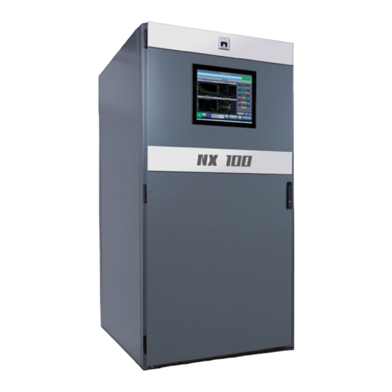
- Page 1 NX100 Transmitter Installation Manual Document: NHB-NX100-INS Issue: 3.2 2017-03-31 Status: Standard...
- Page 3 The comparisons and other information provided in this document have been prepared in good faith based on publicly available information. The reader is encouraged to consult the respective manufacturer's most recent published data for verification. © Copyright 2017 NAUTEL. All rights reserved.
-
Page 5: Table Of Contents
NX100 Installation Manual Table of contents Contents Release control record Preparing for installation Unpacking and positioning Connecting transformer taps/load wiring Connecting the station reference ground Connecting ac power Adjusting the spark gap Installing audio inputs Planning complete? Routing cables Setting Exgine audio parameters... - Page 6 NX100 Installation Manual Table of contents Parts and tools 10-1 Contacting Nautel 10-1 Parts supplied by Nautel 10-1 Parts not supplied by Nautel 10-2 Parts ordering 10-2 Module replacement program 10-2 Tools for installation 10-3 Pre-installation / Installation assistance 11-1...
-
Page 7: Release Control Record
NX100 Installation Manual Release control record Issue Date Reason 2012-11-01 Release 3 of product (NARA52B) 2016-02-08 Section 9, sub-paragraph Turning on the Transmitter: improved and added various steps. Section 9, sub-paragraph Modulation Checks: added NOTE after step 4 to maintain positive and negative modulation peaks within specification. - Page 8 NX100 Installation Manual Page viii Issue 3.2 2017-03-31...
-
Page 9: Preparing For Installation
8. Gather the parts and tools you will need for installation. For a list of required tools, see “Parts and tools” on page 10-1. 9. When you are ready to install the NX100 transmitter, follow the steps shown in Figure 1.1 on page 1-2. -
Page 10: Unpacking And Positioning
NX100 Installation Manual Preparing for installation Figure 1.1: Flowchart - Installing the transmitter Unpacking and positioning - see page 2-1 Connecting transformer taps/load wiring - see page 3-1 Connecting the station reference ground - see page 4-1 Connecting ac power - see page 5-1... -
Page 11: Unpacking And Positioning
To install an NX100 transmitter, perform the following tasks: 1. Lift and slide the transmitter cabinets off the base of their crates. The NX100 contains two main crates - a control cabinet and a transformer cabinet. Crated and uncrated cabinet... - Page 12 (see the NX100 Pre-Installation Manual for details), follow the installation steps below: • Obtain the cover plate (Nautel Part # 207-8211) packed with the NX100 ancillaries. • Remove the nine (9) M4 screws that secure the filter brackets to the rear door and remove the air filter and brackets (see Figure 2.2 on page...
- Page 13 Unpacking and positioning 6. Install the antenna ground switch on top of the transmitter cabinet as follows: • Locate the antenna ground switch (Nautel Part # 207-8320-04) that was packed with the ancillary crate for shipping. • Open the front door of the transmitter and unlock and open the filter door to gain access to the inside of the transmitter cabinet.
- Page 14 NX100 Installation Manual Unpacking and positioning 11. Obtain four stiffener brackets [Nautel Part # 207-8296 (qty 1), 207-8296-01 (qty 1) and 207-8296-02 (qty 2)] for each transmitter cabinet from the ancillary kit. Install them on the top of each cabinet as shown in Figure 2.5 on page...
- Page 15 NX100 Installation Manual Unpacking and positioning Figure 2.2: Installing Rear Plate and Removing Top Cover Plate - Closed Air Cooling Partial Rear View Remove the 9 M4 screws that secure the filter bracket. Use same holes and hardware to install cover plate.
- Page 16 NX100 Installation Manual Unpacking and positioning Figure 2.3: Installing Antenna Ground Switch Antenna Ground Switch (Nautel Part # 213-8320-04) Four sets of M4 hardware (packed with antenna ground switch) Aluminum Rod (secure to probe bracket with M8 hardware, packed with...
- Page 17 NX100 Installation Manual Unpacking and positioning Figure 2.4: Location of Arc Detector Assembly Arc Detector Assembly (A71) Partial Rear View; Rear Door Removed for Clarity Issue 3.2 2017-03-31 Page 2-7...
- Page 18 NX100 Installation Manual Unpacking and positioning Figure 2.5: Installing Stiffener Brackets Install stiffener brackets to create a frame as shown. Remove and re-use the hardware securing the exhaust duct grill to secure the brackets. Single-cabinet transmitter shown. For multi-cabinet transmitters, repeat installation for each cabinet.
-
Page 19: Connecting Transformer Taps/Load Wiring
It is important to choose the correct tap based on the loaded line-to-line voltage (i.e., the line voltage present when the NX100 is operating at full power and full modulation) for maximum peak modulation capability and maximum efficiency. If the loaded line-to-line voltage falls between two tap settings, choose the higher voltage tap (this will maximize the NX100‘s power factor). - Page 20 NX100 Installation Manual Connecting transformer taps/load wiring Figure 3.1: NX100 power transformer line voltage tap layout Figure 3.2: Phase connection to transformer tap PHASE CONNECTION (FOUR COPPER STRAPS) Page 3-2 Issue 3.2 2017-03-31...
- Page 21 This wiring may be supplied by Nautel and packed in the main cabinet or packed in the ancillary crate. If it is not provided by Nautel, it must be obtained by the user. In this case, select the wiring based on the recommendations in the Electrical Requirements section of the NX100 Pre-installation Manual.
- Page 22 NX100 Installation Manual Connecting transformer taps/load wiring Figure 3.3: NX100 Ac Power Connections to Cabinet AC CABLE ENTRY AC CABLE DUCT TO TOP OF TRANS- MITTER Xo STANDOFF TERMINAL AC TERMINALS AC1/AC2/AC3 (PROTECTIVE LEXAN COVER NOT SHOWN) REAR/SIDE VIEW WITH...
- Page 23 NX100 Installation Manual Connecting transformer taps/load wiring Figure 3.4: Installing Cytolok Cable Connectors TWO SIZES USED: Nautel Part # JA92 for 1/0 AWG wire Nautel Part # JA93 for 535 MCM wire (NOTE: JA93 can be used for 500-600 MCM) WIRE Cytoloks connectors can be found in the ancillary kit.
- Page 24 NX100 Installation Manual Connecting transformer taps/load wiring Page 3-6 Issue 3.2 2017-03-31...
-
Page 25: Connecting The Station Reference Ground
Note: Proper grounding configuration is critical for protecting transmitter circuitry from lightning strikes. See the Electrical Requirements section of the NX100 Pre- Installation Manual or the Recommendations for Transmitter Site Preparation Manual for information on proper grounding and lightning protection recommendation. - Page 26 NX100 Installation Manual Connecting the station reference ground Figure 4.1: Safety Ground Stud Assembly Detail INTERIOR EXTERIOR 1) M10 BRASS STUD 2) M10 NUT 3) M10 FLAT WASHER 4) M10 SPLIT WASHER 5) EXTERIOR REFERENCE GROUND CONDUCTOR 6) CABINET FRAME...
-
Page 27: Connecting Ac Power
Nautel may provide an EMERGENCY STOP switch. Close the ac power disconnect switch’s front door. 5. Route the load wiring from the ac power disconnect switch to the transformer cabinet, passing all the conductors, as a group, through a ferrite toroid (Nautel Part # LX63, provided in the ancillary kit).. Note: The preferred entry point for ac input wiring is through a hole in the primary side of the transformer cabinet. - Page 28 NX100 Installation Manual Connecting ac power 8. Connect the ac line input to the H1 (Line 1), H2 (Line 2) and H3 (Line 3) input terminals on the transformer (see Figure 4.1 on page 4-2). Connect the ac ground to the transformer’s ground stud.
-
Page 29: Adjusting The Spark Gap
Section 6: Adjusting the spark gap The NX100’s RF output filter contains a spark gap that must be adjusted - based on site altitude - to provide protection against excessive voltage (i.e., lightning) on the RF output. If the altitude of the transmitter site is known prior to transmitter delivery, then the spark gap is adjusted at Nautel. - Page 30 NX100 Installation Manual Adjusting the spark gap Figure 6.1: RF Output Spark Gap Location ACCESS SPARK GAP FROM FRONT OF TRANSMITTER SPARK GAP (E1) WITH FRONT DOOR AND FILTER DOOR OPEN Page 6-2 Issue 3.2 2017-03-31...
- Page 31 NX100 Installation Manual Adjusting the spark gap Table 6.1: Altitude Scale Factor Spark Gap Scale Factor Altitude (ft) (multiply gap by...) 1.00 1,000 1.05 2,000 1.10 3,000 1.15 4,000 1.20 5,000 1.26 6,000 1.32 7,000 1.39 8,000 1.46 9,000 1.54 10,000 1.62...
- Page 32 NX100 Installation Manual Adjusting the spark gap Page 6-4 Issue 3.2 2017-03-31...
-
Page 33: Installing Audio Inputs
1. Route all audio cables from their audio sources to the top of the transmitter. 2. Get two ferrite toroids (one each of Nautel Part # LXP44 and LP23) from the ancillary kit. 3. Pass all audio input cables through the ferrite toroids obtained in Step 2. - Page 34 NX100 Installation Manual Installing audio inputs Figure 7.1: Passing Audio Input Wiring Through Ferrite Toroids LXP44 & LP23 ferrite toroids Program Input Cable (to exciters panel) Figure 7.2: Audio Cable Entry AUDIO CABLE ENTRY Page 7-2 Issue 3.2 2017-03-31...
- Page 35 NX100 Installation Manual Installing audio inputs Figure 7.3: Audio Connections (Exciter Panel shown) BALANCED ANALOG 1 PPS ANALOG 10 MHz AES/EBU AES/EBU AUDIO SYNC SYNC CONTROL/INTERFACE PWB Issue 3.2 2017-03-31 Page 7-3...
-
Page 36: Setting Exgine Audio Parameters
Use the transmitter’s AUI to set and adjust Exgine audio parameters as follows (refer also to the Operating section of the NX100 Operations and Maintenance Manual): From the AUI select Menu -> User Settings -> Exgine Settings . The menu in Figure 7.4... - Page 37 NX100 Installation Manual Installing audio inputs Figure 7.5: Digital Settings menu Issue 3.2 2017-03-31 Page 7-5...
- Page 38 NX100 Installation Manual Installing audio inputs Page 7-6 Issue 3.2 2017-03-31...
-
Page 39: Installing Control/Monitor Wiring
Routing cables 1. Route all remote control/monitor cables to the top of the transmitter. 2. Get two (2) ferrite toroids (one each of Nautel Part # LXP44 and LP23) from the ancillary kit. 3. Pass all remote control/monitor cables through the ferrite toroids obtained in Step 2. - Page 40 ENTRY 7. Connect the appropriate control/monitor cable(s) to the connector(s) described in Section 8 of the NX100 Pre-installation Manual.. Secure wires to the existing cabling and to the panel using arrowhead tyraps provided in the ancillary kit (see Figure 8.3 on page 8-3 to locate tyrap anchor hole locations).
- Page 41 NX100 Installation Manual Installing control/monitor wiring Figure 8.3: Remote Interface Connections Digital Arrowhead tyrap Outputs anchor holes External +15V IN Analog Out- puts Digital Inputs A4 - REMOTE INTERFACE PWB External System Interlock and PDM Inhibit connections, as applicable Issue 3.2 2017-03-31...
- Page 42 NX100 Installation Manual Installing control/monitor wiring Figure 8.4: Web Interface Connection Secure to existing ETHERNET cable with tyraps Connect to left-hand (LAN1) connector Page 8-4 Issue 3.2 2017-03-31...
-
Page 43: Commissioning Tasks
4. Confirm that the taps are configured correctly. 5. Remove the rear filters from the transmitter and spray them with filter coat adhesive spray (Nautel Part # HQ59), located in the ancillary kit. Re-install the rear filters on the transmitter. - Page 44 NX100 Installation Manual Commissioning tasks 6. Terminate the transmitter's RF output into a precision, 50 , resistive dummy load that is able to dissipate the RF power being applied to it: 150 kW total required. 7. Verify that all panels are installed, and ensure that their attaching hardware is firmly tightened.
-
Page 45: Commissioning
NX100 Installation Manual Commissioning tasks Commissioning Turning on the transmitter 1. Switch on the ac power at the service entrance to turn on the transmitter. 2. Check the alarm and status indications on the control cabinet’s AUI using the Transmitter Status page of the AUI. - Page 46 Manual for detailed information set up preset modes. See the NX100 Operations and Maintenance Manual. 16. Set the time and date on the AUI display. See the NX100 Operations and Maintenance Manual. 17. Using a web browser go to ftp://www3.nautel.com/NX_Series/ to make sure your software version is the latest available.
- Page 47 NX100 Operations and Maintenance Manual for detailed information. 21. Use the local or remote AUI to configure your desired remote inputs and outputs. See the “Operating the Transmitter” section of the NX100 Operations and Maintenance Manual for detailed information.
-
Page 48: Going On-Air
2. Connect the transmitter's RF output to an antenna system (or verify that the current connection is intact). Ensure that a ferrite toroid (Nautel Part # LX63) is installed on the RF coaxial hardline at the transmitter’s output. 3. Turn the transmitter’s ac power back on. -
Page 49: Parts And Tools
Parts supplied by Nautel Ancillary parts kit An ancillary parts kit is shipped with the NX100. This kit contains hardware needed during the installation process. The kit includes toroids, spare fuses, screws and other miscellaneous hardware. Issue 3.2 2017-03-31... -
Page 50: Parts Not Supplied By Nautel
See “NX100 transmitter manuals” on page xii Parts not supplied by Nautel Some parts and materials required to complete installation are not supplied by Nautel. The parts you need vary with the installation requirements. The list of parts you normally provide yourself during installation include: A suitable 50 ... -
Page 51: Tools For Installation
NX100 Installation Manual Parts and tools Tools for installation The tools you need during transmitter installation include the following: • Digital voltmeter • Philips screwdrivers, sizes #1 and #2 • Pliers • Wire cutters • Slot screwdriver, 5 mm (3/16 inch) •... - Page 52 NX100 Installation Manual Parts and tools Page 10-4 Issue 3.2 2017-03-31...
-
Page 53: Pre-Installation / Installation Assistance
Pre-installation consulting Nautel field support specialists are available to answer questions and work with you to ensure that your site will be ready for the installation of your NX100 transmitter. For support, contact Nautel Customer Service and request assistance (“On-site support” on page... - Page 54 Ac power wiring for the transmitter has been installed and connected at the breaker panel or the building’s service entrance. If local electrical codes allow Nautel personnel to connect the transmitter to the ac supply, using the customer's cable, that task is included in this service.
-
Page 55: Online Documentation
Nautel training programs are made up of individual modules that can be 'mixed and matched' to meet the customer’s specific training needs. All Nautel training courses are available at the Nautel Training Center. -
Page 56: Standard Warranty
4. If the Buyer receives a replacement module, as part of Nautel's module exchange program, the old module must be returned to Nautel within 30 days of receipt of the new module, at the buyers expense. If the old module is not received after 30 days, the customer will be invoiced. The buyer is responsible for installing the replacement/repaired module in the transmitter. - Page 57 Buyer's expense. Where no-charge warranty replacements or repairs are provided under items 2, 3, 4, or 5, Nautel will pay that part of the shipping costs incurred in returning the part/assembly to the Buyer. Note: the Buyer is responsible for any and all import fees, duties or taxes.
- Page 58 Pre-installation / Installation assistance 13. Nautel provides telephone and email support for its products for the life of the product at no charge. After the warranty period, parts and on-site support for the equipment are offered at a rate to be determined upon request.
- Page 59 Pre-installation / Installation assistance Module exchange service In order to provide Nautel customers with a fast and efficient service in the event of a problem, Nautel operates a factory rebuilt, module exchange service which takes full advantage of the high degree of module redundancy in Nautel equipment.
-
Page 60: Extended Warranties
Extended warranties Nautel's standard four-year warranty provides excellent coverage and satisfies most customers’ needs. However, if you want extended coverage, Nautel offers one and two-year Extended Warranty Plans to cover electrical and mechanical repairs or replacements for all Nautel equipment. - Page 61 If Nautel’s service technicians are unable to solve the problem over the telephone, Nautel will give you an RMA number. You then return the module or circuit board to a Nautel service facility so that Nautel can provide a replacement. (Do not ship a component back to Nautel until you have an RMA number.)
- Page 62 NX100 Installation Manual Pre-installation / Installation assistance Page 11-10 Issue 3.2 2017-03-31...
-
Page 63: List Of Terms
NX100 Installation Manual List of terms Section 12: List of terms This section defines some of the terms that are used in Nautel documentation. ADC. Analog to Digital Converter. AES-EBU. Audio Engineering Society/European Broadcasting Union (AES/EBU) is the name of a digital audio transfer standard. - Page 64 A setting that controls power level, active exciter, and power scheduler status on a time-of- day and date basis. Exciters can be configured on a preset for a specific operating mode (for example, Exciter A - conventional AM, and Exciter B - IBOC). The NX100 allows you to pre-program multiple presets.
- Page 66 Phone: +1.902.823.3900 or Fax: +1.902.823.3183 Nautel Inc. 201 Target Industrial Circle Bangor, Maine USA 04401 Phone: +1.207.947.8200 Fax: +1.207.947.3693 Customer Service (24-hour support) +1.877.628.8353 (Canada & USA only) +1.902.823.5100 (International) Email: support@nautel.com Web: www.nautel.com © Copyright 2017 NAUTEL. All rights reserved.
Need help?
Do you have a question about the NX100 and is the answer not in the manual?
Questions and answers