Table of Contents
Advertisement
Quick Links
ACDEU
OM-04529-03
November 18, 2005
INSTALLATION, OPERATION,
AND MAINTENANCE MANUAL
WITH PARTS LIST
10 SERIES PUMPS
MODEL
14D1−GX390
THE GORMAN-RUPP COMPANY D MANSFIELD, OHIO
www.gormanrupp.com
D
GORMAN-RUPP OF CANADA LIMITED
ST. THOMAS, ONTARIO, CANADA
Printed in U.S.A.
e
Copyright by the Gorman-Rupp Company
Advertisement
Table of Contents

Related Manuals for GORMAN-RUPP PUMPS 14D1-GX390


Summary of Contents for GORMAN-RUPP PUMPS 14D1-GX390
- Page 1 ACDEU OM-04529-03 November 18, 2005 INSTALLATION, OPERATION, AND MAINTENANCE MANUAL WITH PARTS LIST 10 SERIES PUMPS MODEL 14D1−GX390 THE GORMAN-RUPP COMPANY D MANSFIELD, OHIO www.gormanrupp.com GORMAN-RUPP OF CANADA LIMITED ST. THOMAS, ONTARIO, CANADA Printed in U.S.A. Copyright by the Gorman-Rupp Company...
- Page 2 The engine exhaust from this product contains chemicals known to the State of California to cause cancer, birth defects or other reproductive harm.
-
Page 3: Table Of Contents
TABLE OF CONTENTS INTRODUCTION ..........PAGE I −... - Page 4 TABLE OF CONTENTS (continued) PARTS LISTS: Pump Model ............PAGE E −...
-
Page 5: Introduction
10 SERIES OM−04529 INTRODUCTION Thank You for purchasing a Gorman-Rupp pump. promised by the installation. Pumps and related Read this manual carefully to learn how to safely equipment must be installed and operated ac- install and operate your pump. Failure to do so cording to all national, local and industry stan- could result in personal injury or damage to the dards. -
Page 6: Safety - Section A
10 SERIES OM−04529 SAFETY − SECTION A This information applies to 10 Series en- gine driven pumps. Refer to the manual accompanying the engine before at- tempting to begin operation. This pump is designed to handle dirty water containing specified entrained This manual will alert personnel to solids. - Page 7 10 SERIES OM−04529 gaged to be ejected with great force. Al- low the pump to completely cool before servicing. Never tamper with the governor to gain more power. The governor establishes safe operating limits that should not be exceeded. The maximum continuous operating speed for this pump is 3100 Do not operate an internal combustion RPM.
-
Page 8: Installation − Section Bpage B
10 SERIES OM−04529 INSTALLATION − SECTION B Review all SAFETY information in Section A. specific application. Since the pressure supplied to the pump is critical to performance and safety, Since pump installations are seldom identical, this be sure to limit the incoming pressure to 50% of the section offers only general recommendations and maximum permissible operating pressure as practices required to inspect, position, and ar-... -
Page 9: Preinstallation Inspection
OM−04529 10 SERIES PREINSTALLATION INSPECTION piping must be removed from the pump before lifting. The pump assembly was inspected and tested be- Lifting fore shipment from the factory. Before installation, inspect the pump for damage which may have oc- Pump unit weights will vary depending on the curred during shipment. -
Page 10: Suction And Discharge Piping
10 SERIES OM−04529 suction and discharge ports and install the lines. SUCTION AND DISCHARGE PIPING Installation closer to the pump may result in erratic readings. Pump performance is adversely effected by in- SUCTION LINES creased suction lift, discharge elevation, and fric- tion losses. -
Page 11: Suction Lines In Sumps
OM−04529 10 SERIES Suction Lines In Sumps of one or both pumps. To avoid this, position the suction inlets so that they are separated by a dis- If a single suction line is installed in a sump, it tance equal to at least 3 times the diameter of the should be positioned away from the wall of the suction pipe. -
Page 12: Discharge Lines
10 SERIES OM−04529 DISCHARGE LINES Siphoning If the application involves a high discharge Do not terminate the discharge line at a level lower head, gradually close the discharge than that of the liquid being pumped unless a si- phon breaker is used in the line. Otherwise, a si- throttling valve before stopping the pump. -
Page 13: Operation − Section C
OM−04529 10 SERIES OPERATION − SECTION C Review all SAFETY information in Section A. Add liquid to the pump casing when: 1. The pump is being put into service for the Follow the instructions on all tags, labels and first time. decals attached to the pump. -
Page 14: Lines Without A Bypass
OM−04529 10 SERIES line. Air from the suction line will be discharged through the bypass line back to the wet well during the priming cycle. When the pump is fully primed and liquid is flowing steadily from the bypass line, Do not remove plates, covers, gauges, open the discharge throttling valve. -
Page 15: Cold Weather Preservation
OM−04529 10 SERIES shock waves can be transmitted to the pump and Cold Weather Preservation piping system. Close all connecting valves slowly. In below freezing conditions, drain the pump to On engine driven pumps, reduce the throttle prevent damage from freezing. Also, clean out any speed slowly and allow the engine to idle briefly be- fore stopping. -
Page 16: Troubleshooting − Section D
10 SERIES OM−04529 TROUBLESHOOTING − SECTION D Review all SAFETY information in Section A. Before attempting to open or service the pump: 1. Familiarize yourself with this manual. 2. Shut down the engine and take pre- cautions to ensure that the pump will remain inoperative. - Page 17 OM−04529 10 SERIES TROUBLE POSSIBLE CAUSE PROBABLE REMEDY PUMP STOPS OR Air leak in suction line. Correct leak. FAILS TO DELIVER Lining of suction hose collapsed. Replace suction hose. RATED FLOW OR PRESSURE Leaking or worn seal or pump gasket. Check pump vacuum.
-
Page 18: Preventive Maintenance
10 SERIES OM−04529 equipped) between regularly scheduled inspec- PREVENTIVE MAINTENANCE tions can indicate problems that can be corrected Since pump applications are seldom identical, and before system damage or catastrophic failure oc- pump wear is directly affected by such things as curs. -
Page 19: Pump Maintenance And Repair - Section E
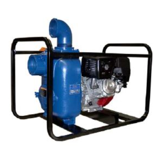
10 SERIES OM−04529 PUMP MAINTENANCE AND REPAIR - SECTION E MAINTENANCE AND REPAIR OF THE WEARING PARTS OF THE PUMP WILL MAINTAIN PEAK OPERATING PERFORMANCE. STANDARD PERFORMANCE FOR PUMP MODELS 14D1−GX390 Based on 70_ F (21_ C) clear water at sea level with minimum suction lift. - Page 20 OM−04529 10 SERIES SECTION DRAWING PARTS PAGE Figure 1. Pump Model 14D1−GX390 PAGE E − 2 MAINTENANCE & REPAIR...
- Page 21 10 SERIES OM−04529 PARTS LIST Pump Models 14D1−GX390 (From S/N 1325668 up) If your pump serial number is followed by an N", your pump is NOT a standard production model. Contact the Gorman-Rupp Company to verify part numbers. ITEM PART MAT’L PART NAME NUMBER...
- Page 22 OM−04529 10 SERIES SECTION DRAWING Figure 2. Pump End Assembly 14D1−(GX390) PAGE E − 4 MAINTENANCE & REPAIR...
- Page 23 10 SERIES OM−04529 PARTS LIST Pump End Assembly 14D1−(GX390) ITEM PART MAT’L PART NAME NUMBER CODE PUMP CASING 38224−505 13040 IMPELLER 38615−011 10010 MECH SEAL ASSY 25285−855 −−− FILL PLUG ASSY 48271−065 −−− GASKET 38687−009 20000 HEX HD CAPSCREW B1005 15991 DISCHARGE FLANGE 38644−506...
- Page 24 OM−04529 10 SERIES PUMP AND SEAL DISASSEMBLY 3. Allow the pump to completely cool AND REASSEMBLY if overheated. 4. Check the temperature before opening any covers, plates, or Review all SAFETY information in Section A. plugs. 5. Close the suction and discharge Follow the instructions on all tags, label and de- cals attached to the pump.
- Page 25 10 SERIES OM−04529 Inspect the wear plate and, if replacement is re- under the rubber bellows. Slide the rotating portion quired, remove the hardware (16 and 17) securing of the seal off the shaft sleeve. it to the back cover. Remove the hardware (10 and 11) and carefully slide the intermediate (12) and stationary portion of Pump Casing Removal...
- Page 26 OM−04529 10 SERIES age. Clean and polish the shaft sleeve, or replace it faces to ensure that they are free of any foreign if there are nicks or cuts on either end. If any com- matter. ponents are worn, replace the complete seal; To ease installation of the seal, lubricate the O- never mix old and new seal parts.
- Page 27 10 SERIES OM−04529 the sleeve (37) until the rotating element is just casing gaskets accordingly. flush with the chamfered end of the sleeve. See Figure 1 and secure the pump casing to the Slide the sleeve and assembled rotating portion of rollover base (4) with the hardware (13, 14 and 15).
- Page 28 OM−04529 10 SERIES Final Pump Assembly Refer to OPERATION, Section C, before putting the pump back into service. (Figure 1) Be sure the pump and engine are securely mounted to the base. LUBRICATION Apply Loctite Pipe Sealand with Teflon" or equiva- lent compound to the threads of the discharge el- bow (2) and screw the elbow into the pump dis- Seal Assembly...
- Page 29 For U.S. and International Warranty Information, Please Visit www.grpumps.com/warranty or call: U.S.: 419−755−1280 International: +1−419−755−1352 For Canadian Warranty Information, Please Visit www.grcanada.com/warranty or call: 519−631−2870 THE GORMAN-RUPP COMPANY D MANSFIELD, OHIO GORMAN-RUPP OF CANADA LIMITED ST. THOMAS, ONTARIO, CANADA...
Need help?
Do you have a question about the 14D1-GX390 and is the answer not in the manual?
Questions and answers