Table of Contents
Advertisement
www.proform.com
USER'S MANUAL
Model No. PFEL06916.0
Serial No.
Write the serial number in the space
above for reference.
Serial Number
Decal
ACTIVATE YOUR
WARRANTY
To register your product and
activate your warranty today,
go to www.proformservice.com/
registration.
CUSTOMER CARE
For service at any time, go to
www.proformservice.com.
Or call 1-888-533-1333
Mon.–Fri. 6 a.m.–6 p.m. MT
Sat. 8 a.m.–12 p.m. MT
Please do not contact the store.
CAUTION
Read all precautions and
instructions in this manual before
using this equipment. Keep this
manual for future reference.
Advertisement
Table of Contents

Related Manuals for Pro-Form SMART STRIDER 695 CSE


Summary of Contents for Pro-Form SMART STRIDER 695 CSE
- Page 1 www.proform.com USER’S MANUAL Model No. PFEL06916.0 Serial No. Write the serial number in the space above for reference. Serial Number Decal ACTIVATE YOUR WARRANTY To register your product and activate your warranty today, go to www.proformservice.com/ registration. CUSTOMER CARE For service at any time, go to www.proformservice.com.
-
Page 2: Table Of Contents
TABLE OF CONTENTS WARNING DECAL PLACEMENT ............. . .2 IMPORTANT PRECAUTIONS . -
Page 3: Important Precautions
IMPORTANT PRECAUTIONS WARNING: To reduce the risk of burns, fire, electric shock, or injury to persons, read all important precautions and instructions in this manual and all warnings on your elliptical before using your elliptical. ICON assumes no responsibility for personal injury or property damage sus- tained by or through the use of this product. - Page 4 18. The heart rate monitor is not a medical 20. Keep your back straight while using the device. Various factors may affect the accu- elliptical; do not arch your back. racy of heart rate readings. The heart rate monitor is intended only as an exercise aid 21.
- Page 5 STANDARD SERVICE PLANS...
-
Page 6: Before You Begin
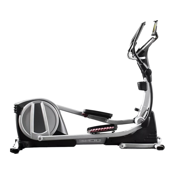
Thank you for selecting the revolutionary PROFORM reading this manual, please see the front cover of this ® SMART STRIDER 695 CSE elliptical. The SMART manual. To help us assist you, note the product model STRIDER 695 CSE elliptical provides an impressive number and serial number before contacting us. -
Page 7: Assembly
ASSEMBLY • To hire an authorized service technician to • In addition to the included tool(s), assembly assemble this product, call 1-800-445-2480. requires the following tool(s): one Phillips screwdriver • Assembly requires two persons. Assembly may be easier if you have a set of •... - Page 8 3. With the help of another person, place some sturdy packing materials under the front of the Frame (1). Have the other person hold the elliptical to prevent it from tipping. If there are shipping supports attached to the front of the Frame (1), remove the screws attach- ing the shipping supports.
- Page 9 5. Rotate the Right Upper Body Arm (9) to the position shown. Attach the Right Upper Body Arm (9) to the Right Upper Body Leg (6) with an M10 x 50mm Screw (95). IMPORTANT: Tighten the indicated M10 x 45mm Hex Screw (78). Press the Upper Body Arm Cover (20) downward and turn it so that it is flush with the Right Leg Front and Rear Covers (11, 15).
-
Page 10: How To Use The Elliptical
HOW TO USE THE ELLIPTICAL HOW TO PLUG IN THE POWER CORD A temporary adapter may 2-pole Receptacle This product must be grounded. If it should malfunc- be used to tion or break down, grounding provides a path of least connect the Adapter resistance for electric current to reduce the risk of elec-... - Page 11 HOW TO MOVE THE ELLIPTICAL HOW TO ADJUST THE POSITIONS OF THE PEDALS Due to the size and weight of the elliptical, moving it requires two persons. Each pedal can be adjusted to First, loosen the several positions. upright knob. To adjust each Next, pull the pedal, simply pull...
- Page 12 HOW TO EXERCISE ON THE ELLIPTICAL See HOW TO MOVE THE ELLIPTICAL on page 11 and lower the upright to the folded position. To mount the elliptical, hold the handlebars or the upper body arms and step onto the pedal that is in the Next, hold the handle (not shown) on the front stabi- lower position.
- Page 13 CONSOLE DIAGRAM FEATURES OF THE CONSOLE The advanced console offers an array of features designed to make your workouts more effective and enjoyable. When you use the manual mode of the console, you can change the resistance of the pedals with the touch of a button.
- Page 14 HOW TO TURN ON THE POWER HOW TO USE THE MANUAL MODE IMPORTANT: If the elliptical has been exposed to 1. Begin pedaling or press any button on the cold temperatures, allow it to warm to room tem- console to turn on the console. perature before you turn on the power.
- Page 15 To set a power output target, press the Watts To vary the motion of the pedals, you can change the incline of the frame. To change the incline, increase and decrease buttons until the desired press the Incline increase and decrease buttons. power output target appears in the display.
- Page 16 7. Follow your progress with the display. Change the volume level of the console by pressing the Vol The display can show the following workout increase and decrease buttons. information: Calories (CALS)—The approximate number of calories you have burned. To pause the console, simply stop pedaling. When the console is paused, the time will flash in the Distance (MI or KI)—The distance that you have display.
- Page 17 10. When you are finished exercising, unplug the When your pulse is detected, your heart rate will be shown in the display. For the most accurate heart power cord. rate reading, hold the contacts for at least 15 seconds. If the pedals do not move for several seconds, a series of tones will sound, the console will pause, If the display does not show your heart rate, make and the display will pause.
- Page 18 HOW TO USE AN ONBOARD WORKOUT At the end of each segment of the workout, a series of tones will sound. The resistance level 1. Begin pedaling or press any button on the for the next segment will appear in the display for console to turn on the console.
- Page 19 5. Follow your progress with the display. THE OPTIONAL CHEST HEART RATE MONITOR See step 7 on page 16. Whether your goal is to 6. Measure your heart rate if desired. burn fat or to strengthen your See step 8 on page 16. cardiovascular system, the key 7.
- Page 20 HOW TO CONNECT YOUR TABLET TO THE 5. Disconnect your tablet from the console if CONSOLE desired. The console supports BLUETOOTH connections to To disconnect your tablet from the console, first tablets via the iFit Bluetooth Tablet app and to compat- select the disconnect option in the iFit Bluetooth ible heart rate monitors.
-
Page 21: Fcc Information
THE SETTINGS MODE Press the Tempo Apps button repeatedly until the console usage information appears in the display. The console features a settings mode that allows you to select a unit of measurement for the console and to The display will alternate view console usage information. -
Page 22: Maintenance And Troubleshooting
MAINTENANCE AND TROUBLESHOOTING MAINTENANCE HOW TO CALIBRATE THE INCLINE SYSTEM Regular maintenance is important for optimal If the incline system is not functioning properly, it may performance and to reduce wear. Inspect and properly need to be calibrated. To calibrate the incline system, tighten all parts each time the elliptical is used. - Page 23 HOW TO ADJUST THE REED SWITCH If the console does not display correct feedback, the reed switch should be adjusted. To adjust the reed switch, first press the power switch to the off posi- tion and unplug the power cord. Next, remove the four M4 x 16mm Screws (not...
- Page 24 HOW TO ADJUST THE DRIVE BELT Next, remove the four M4 x 16mm Screws (not shown) from the Large Storage Foot (27), and then remove If the pedals slip while you are pedaling, even while the the Large Storage Foot. Remove the two M4 x 16mm resistance is adjusted to the highest setting, the drive Screws (not shown) from the Top Shield (37), and use belt may need to be adjusted.
-
Page 25: Exercise Guidelines
EXERCISE GUIDELINES Burning Fat—To burn fat effectively, you must exer- WARNING: cise at a low intensity level for a sustained period of Before beginning this time. During the first few minutes of exercise, your or any exercise program, consult your physi- body uses carbohydrate calories for energy. - Page 26 SUGGESTED STRETCHES The correct form for several basic stretches is shown at the right. Move slowly as you stretch; never bounce. 1. Toe Touch Stretch Stand with your knees bent slightly and slowly bend forward from your hips. Allow your back and shoulders to relax as you reach down toward your toes as far as possible.
-
Page 27: Part List
PART LIST Model No. PFEL06916.0 R1016A Key No. Qty. Description Key No. Qty. Description Frame Small Storage Foot Upright Idler Rear Upright Cover Small Spacer Console Resistance Motor Accessory Tray Axle Cover Right Upper Body Leg M4 x 12mm Washer Head Screw Eddy Mechanism Clamp Left Upper Body Arm... - Page 28 Key No. Qty. Description Key No. Qty. Description Left Upper Body Leg M6 x 16mm Screw Upright Axle Right Pedal Pad M8 x 20mm Hex Bolt Left Pedal Pad Incline Frame Right Pedal Handle Lift Motor Left Pedal Handle Control Board Right Pedal Plate Control Board Bracket Left Pedal Plate...
-
Page 29: Exploded Drawing
EXPLODED DRAWING A Model No. PFEL06916.0 R1016A... - Page 30 EXPLODED DRAWING B Model No. PFEL06916.0 R1016A...
- Page 31 EXPLODED DRAWING C Model No. PFEL06916.0 R1016A...
-
Page 32: Ordering Replacement Parts
ORDERING REPLACEMENT PARTS To order replacement parts, see the front cover of this manual. To help us assist you, please be prepared to provide the following information when contacting us: • the model number and serial number of the product (see the front cover of this manual) •...
Need help?
Do you have a question about the SMART STRIDER 695 CSE and is the answer not in the manual?
Questions and answers