Advertisement
Quick Links
XLT50-D/XLT50-S 3-Axis Stepper Drive
General Description
Based upon the XL50 single axis drive, the XLT50-D/-S offers a cost-effective 3-axis drive
solution in a single open-frame package. The XLT50-D/-S offers the following benefits:
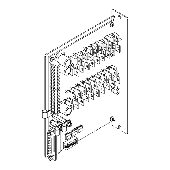
Physical Appearance
The drive is contained within an open-frame aluminium case as shown in Figure A-1.
Mounting holes allow it to be attached to a panel using two 4mm screws.
1600.322.01 April 2003
XLT50-D/XLT50-S 3-AXIS STEPPER DRIVE
•
Reliable design based upon the XL50
•
Cost-effective solution for 3-axis application
•
Available with differential (-D) or single-ended (-S) inputs
Figure A-1. XTL50 Drive
1
Advertisement

Related Manuals for Parker XLT50-D


Summary of Contents for Parker XLT50-D
- Page 1 XLT50-D/XLT50-S 3-AXIS STEPPER DRIVE XLT50-D/XLT50-S 3-Axis Stepper Drive General Description Based upon the XL50 single axis drive, the XLT50-D/-S offers a cost-effective 3-axis drive solution in a single open-frame package. The XLT50-D/-S offers the following benefits: • Reliable design based upon the XL50 •...
- Page 2 XLT50-D/XLT50-S 3-AXIS STEPPER DRIVE Dimensions The overall dimensions of the drive are 141mm deep, 40mm wide (including P-clips) and 172mm high. The distance between centre fixings is 185mm and the overall height of the flange mount is 195mm. Mounting Information Mount the drive vertically.
- Page 3 XLT50-D/XLT50-S 3-AXIS STEPPER DRIVE Drive Layout & Connector Positions Figure A2 shows the location of connectors X1, X4/5 and the bit switch, together with the solder bridge contacts and LED. Pin 1 X4/5 Surface mount bi-coloured LED Pin 16 1 2 3 4 5 6 1 2 3 4 5 6 Figure A-2.
-
Page 4: Power And Motor Connections
XLT50-D/XLT50-S 3-AXIS STEPPER DRIVE Power and Motor Connections Make all DC input connections to the upper part of X4/5, the lower screw connections are used for motor outputs, detailed in Table A-1. Pin N of X4/X5 Function HV (24-85V) 0V (return for HV) - Page 5 XLT50-D/XLT50-S 3-AXIS STEPPER DRIVE Motor Connections (at the motor) Make motor connections directly between the drive and motor, do not use any switching devices, such as a contactor, in the motor supply cables. The majority of applications use an eight-lead motor with the windings connected in parallel or series, as shown in Figure A-3.
-
Page 6: Input Configuration
Control XLT50 Drive Input Configuration The XLT50 drive is available in two versions: • XLT50-D Differential step/direction inputs • XLT50-S Single-ended step/direction inputs The use of differential inputs gives the option of good electrical noise immunity and finds greatest use where control signals have to be routed long distances in electrically noisy environments. - Page 7 XLT50-D/XLT50-S 3-AXIS STEPPER DRIVE Table A-3 lists the signal functionality for a single-ended input drive. Function (differential input) Function (differential input) Step 1- Direction 1- Step 2- Direction 2- Step 3- Direction 3- Shutdown (bar) 1 Shutdown (bar) 2 Shutdown (bar) 3...
- Page 8 XLT50-D/XLT50-S 3-AXIS STEPPER DRIVE Drive Shutdown 10nF Figure A-6. Shutdown Input Circuit Configuration The Shutdown input circuit forms a filter that introduces an approximate 1mS delay, which reduces the chances of false triggering of the Shutdown input. Fault Ouputs The individual Fault 1, 2 & 3 outputs indicate an over-current fault has occurred on a particular axis (1, 2 or 3).
-
Page 9: Bit Switch Settings
XLT50-D/XLT50-S 3-AXIS STEPPER DRIVE Bit Switch Settings The bit switch mounted behind connector X1 controls the resolution of the drive in steps/rev. The switch also controls the current level settings of the individual axes as a percentage of the full output current obtainable. Resolution is set using bit switches 1 and 2, as indicated in Table A-5. - Page 10 XLT50-D/XLT50-S 3-AXIS STEPPER DRIVE Solder Bridge Pads Next to the bit-switch are six solder bridge pads numbered 1 to 6. By bridging the pad with solder the functionality of each axis can be adjusted, as follows: CAUTION – Risk of equipment damage You must observe electrostatic precautions before attempting to make any changes to the drive.
-
Page 11: Functional Specification
XLT50-D/XLT50-S 3-AXIS STEPPER DRIVE Functional Specification Parameter Value Amplifier type MOSFET chopper Motor resolution 400, 800, 2000, 4000 steps/rev Maximum stepping rate 200kHz at 4000 steps/rev Nominal chopping frequency 20kHz (XLT50) Protection circuits Short circuit (phase-to-phase, across phases and phase to ground), motor overcurrent,... - Page 12 XLT50-D/XLT50-S 3-AXIS STEPPER DRIVE Drive Environment Specification Parameters All drive types Environment Pollution degree 2, Installation category II Operating temperature range 0 to 50°C ambient Storage temperature range -20 to 70°C Humidity 5 to 95% non-condensing Cooling Natural convection Housing...
Need help?
Do you have a question about the XLT50-D and is the answer not in the manual?
Questions and answers