Advertisement
Quick Links
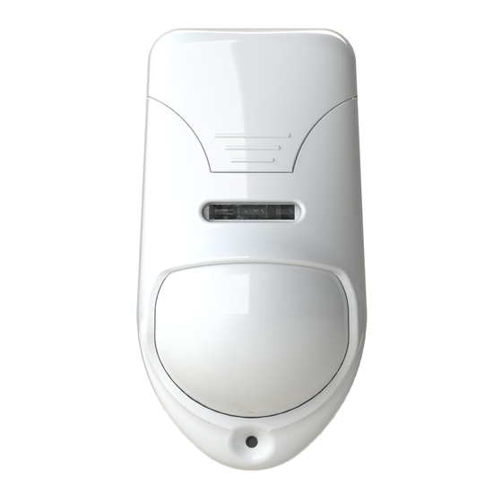
SECURITY COMBINED PIR +
General Information
Security combined detector «Pyrone-7» (hereinafter, the Detector)
is designed for application as a component of security systems.
The Detector has the following two independent detection channels:
- Glass break channel (hereinafter, GB channel);
- Passive infrared channel (hereinafter, PIR channel).
GB channel is intended for detecting destruction of engineering
structures made of plate glasses as well as glass bricks.
PIR channel is assigned for detecting intrusion into protected area
of closed premises.
The Detector is resistant to the impacts of ambient light, radio noise,
as well as disturbance from small animals: mice, rats, birds in cages
if a distance to them is not less than 2,5 m.
The Detector can be installed on the wall or in the corner of the room.
Features
- Sensing element of detection channels:
PIR channel - dual-element pyrodetector;
GB channel - microphone.
- Spherical lens provides high detectability.
- Microprocessor-based signal processing.
- Self-test mode.
- Possibility of PIR and GB channels sensitivity modes changing.
- Protection against ingress of insects to the pyrodetector.
Specifications
Table 1
Parameter
PIR channel detection zone
Maximum detection range
- GB channel
- PIR channel
Output PIR and GB relay contacts
Power supply voltage
Current in standby mode, not more than
Sensitivity of:
- GB channel (high frequency)
- PIR channel
Minimum controlled glass area
Warm-up time after switching on, not
more than
Operating temperature
Relative humidity at +25 °C without
moisture condensation
IP rating
Dimensions, max
Weight, not more
Service life
PIR channel detection zone pattern is shown in Figure 1.
GB channel detection zone pattern is shown in Figure 2.
The Detector ensures safe operation under the impact of sinusoidal
vibration with acceleration of 0,981 m/s
range 10 – 55 Hz.
12 m
Figure 1 – PIR channel detection zone pattern
GLASS BREAK DETECTOR
«Pyrone-7»
Installation Guide
Value
12 х 10 m
6 m
12 m
voltage up to 42 V,
current up to 30 mA
9 ...17 V
35 mА
select:
minimal/+12 dB
high/norm
0,1 m
2
60 s
from minus 20 °С up to +45 °С
90 %
IP30
110 х 58 х 45 mm
0,1 kg
8 years
2
(0,1 g) within the frequency
12 m
Structure of any
sensing zone
180
о
Microphone
6 m
orientation
R
Reliable-detection
top view
Figure 2 – GB channel detection zone pattern
Scope of Delivery
Each Detector unit package contains the items listed in Table 2.
Table 2
Name
Security combined detector "Pyrone-7"
Security combined detector "Pyrone-7". Installation Guide
LED Indication
LED indicators on the front cover are used for the Detector state
displaying. Messages indication is fulfilled in accordance with the Table 3.
Table 3
LED
Detector
state
Red
Yellow
Norm
OFF
OFF
ON
-
Switching ON
50 s
ALARM GB
ON
ON
ALARM PIR
ON
-
Power supply
Blinking
Blinking
voltage drop
1 Hz
1 Hz
Interfering
signal at 1
-
ON
frequency
Interfering
signal at 2
-
-
frequency
Choosing Place of Installation
When choosing the Detector installation place, it is advisable to
take note of the fact that the detection zone may be limited by non-
transparent objects (curtains, houseplants, cabinets, bookcases,
etc.), as well as by glass and mesh partitions. There must be no
windows, air conditioners, space heaters or heating radiators in the
PIR detection zone.
Distance between the Detector and the farthest point of the
monitored glass should not exceed 6 m. The Detector microphone
should be oriented strictly towards the protected surface of a glass
construction.
In case of 1 m
area monitoring maximal distance to the Detector
2
should be increased up to 9 m. Recommended installation height is
2,3 m.
The Detector wires should be laid at a distance not less than 0,5 m
from power supply cables.
Installation of the Detector
- Put off access hole of the Detector (2);
- Remove cover with the printed circuit board (PCB) (4,3) from the
base (1) by pulling towards yourself and downward;
- Open the holes in the base for the Detector wiring and fastening
the base;
- Choose the place of installation, mark the places for mounting holes
with regard to the openings on the detector base, drill holes in the place
of installation;
- Pass the wire through the mounting holes in the base, leaving enough
length of the wire for hooking up to the Detector terminals;
- Fix the base of the detector on the chosen place;
- Install cover with PCB to the base.
2
1
5
Figure 3 – Design of the Detector
6 m
R
90
о
area
side view
Relay
Green
AL1
OFF
Closed
Opened for not
Opened for not
ON 3 s
less than 3 s
less than 50 s
Opened for not
ON
less than 2 s
Opened for not
-
-
less than 2 s
Blinking
Opened for not
Opened for not
1 Hz
less than 2 s
less than 2 s
-
-
ON
-
3
4
Qnt
1 pc.
1 copy
AL2
Closed
-
-
-
Advertisement

Related Manuals for Rielta Pyrone-7


Summary of Contents for Rielta Pyrone-7
- Page 1 Each Detector unit package contains the items listed in Table 2. General Information Table 2 Security combined detector «Pyrone-7» (hereinafter, the Detector) is designed for application as a component of security systems. Name The Detector has the following two independent detection channels: Security combined detector ”Pyrone-7”...
- Page 2 «SENS GB» DIP-switch applying and repeat of GB testing procedure. Rev. 4 of 29.03.17 Made in Russia №Э00291 «RIELTA» JSC, www.rielta.ru Chapaeva Str. 17, Saint Petersburg Russian Federation 197101, rielta@rielta.ru Tel./fax: +7 (812) 233-0302, 703-1360, Technical support, tel. +7 (812) 233-29-53, 703-13-57, support@rielta.ru...
Need help?
Do you have a question about the Pyrone-7 and is the answer not in the manual?
Questions and answers