TYAN Transport GX18 Service Engineer's Manual
Hide thumbs
Also See for Transport GX18:
- Specification (2 pages) ,
- Quick installation manual (2 pages) ,
- Service engineer's manual (33 pages)
Table of Contents
Advertisement
Quick Links
Advertisement
Table of Contents

Related Manuals for TYAN Transport GX18


Summary of Contents for TYAN Transport GX18
- Page 1 Transport GX18/Trophy NR18 B5365N18P3 B5365GR18S2 Service Engineer’s Manual...
- Page 3 TYAN retains the right to make changes to product descriptions and/or specifications at any time, without notice. In no event will TYAN be held liable for any direct or indirect, incidental or consequential damage, loss of use, loss of data or other malady resulting from errors or inaccuracies of information contained in this document.
- Page 4 Federal Communications Commission (FCC) Notice for the USA Compliance Information State- ment (Declaration of Conformity Procedure) DoC FCC Part 15: This device complies with part 15 of the FCC Rules Operation is subject to the following conditions: 1) This device may not cause harmful interference, and 2) This device must accept any interference received including inter- ference that may cause undesired operation.
- Page 5 About this Manual This manual provides you with instructions on installing your Transport GX18/Trophy NR18. This manual is intended for experi- enced users and integrators with hardware knowledge of personal computers. This manual consists of the following parts Chapter 1:...
- Page 6 SAFETY INFORMATION Before installing and using the Transport GX18/Trophy NR18, take note of the following precautions: – Read all instructions carefully. – Do not place the unit on an unstable surface, cart, or stand. – Do not block the slots and opening on the unit, which are pro- vided for ventilation.
-
Page 7: Table Of Contents
Chapter 1:Overview 1.1 About the Transport GX18/Trophy NR18 B5365 ... . . 1 1.2 Features ..........2 1.2.1 Box Contents . -
Page 9: Chapter 1:Overview
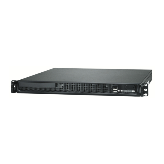
Chapter 1: Overview About the Transport GX18/Trophy NR18 B5365 Congratulations on your purchase of the TYAN Transport GX18/Trophy NR18 (B5365), a highly-optimized rack- mountable barebone system. The Transport GX18/Tro- NR18 (B5365) offers the latest processor server sys- tem, providing a rich feature set and incredible performance. -
Page 10: Features
3.5” SATA or • D-Sub 15-pin VGA port x1 (B5365N18P3) HDD x1 • Two USB 2.0 ports with a dual- stacked USB connector + RJ-45 x1 Transport GX18 2.5” SATA • RJ-45 LAN connector includes (B5365GR18S2) HDD x2 only Transformer & LED x2 (Dual... - Page 11 • Full-loading: under 45dB (measure • Power Cord x1 point: 100cm away from IO) • Extending Mounting Plate • Cable kit: Trophy NR18 Transport GX18 40-pin IDE cable x1 40-pin IDE cable x1 (for IDE HDD) (for CD-ROM) SATA cable x1...
-
Page 12: Box Contents
1.2.1 Box Contents The box includes the following main units. Transport GX18 Trophy NR18 Heatsink x2 Heatsink x2 Power Cord (US type) Power Cord (US type) 1 x Driver CD 1 x Driver CD S5365/B5365 User’s Manual S5365/B5365 User’s Manual... - Page 13 Transport GX18 Trophy NR18 Slim-type CD-ROM Cable IDE Cable for 3.5” HDD SATA Power Cable Slim CD-ROM IDE Board & Screws PCI-E 8X Riser Card PCI-E 8X Riser Card Screw Kit for 3.5” HDD Screw Kit for 2.5” HDD Extending Mounting Plate &...
-
Page 14: About The Product
About the Product 1.3.1 Front View B5365GR18S2 (Transport GX18) USB x 2 Power on Swtich Reset Button LAN2 LED LAN1 LED Alarm Mute Button CD-ROM Drive HDD Activity LED Fan Failure LED Power LED B5365N18P3 (Trophy NR18) USB x 2... -
Page 15: Rear View
1.3.2 Rear View B5365GR18S2 (Transport GX18) Power Supply Socket PS/2 MS/KB PCI-E Slot Power Switch LAN Port + USB x 2 Serial Port VGA Port LAN Port x 2 B5365N18P3 (Trophy NR18) Power Supply Socket Power Switch FAN x 3... -
Page 16: Internal View
1.3.3 Internal View Trophy NR18 1. EPS 12V Power Supply 2. System Fans 3. 3.5” HDD Bay 4. CPU Sockets 5. PCI-E 8X Slot 6. PCI-E 8X Card Holder 7. Memory Slots 8. Front Panel LED Board Chapter 1: Overview... - Page 17 Transport GX18 1. PCI-E 8X Slot 2. Memory Slots 3. EPS 12V Power Supply 4. CPU Socket 5. Front Panel LED Board 6. System Fans 7. 2.5” HDD + Slim CD-ROM 8. PCI-E 8X Card Holder Chapter 1: Overview...
-
Page 18: Mainboard Block Diagram
1.3.4 Mainboard Block Diagram Chapter 1: Overview... -
Page 19: Mainboard Layout
1.3.5 Motherboard Layout DDRII A1 DDRII B1 DDRII A2 DDRII B2 DDRII A3 CPU1 DDRII B3 VGA1 DDRII A4 DDRII B4 CPU2 CPU2 E7520 LAN1 PCIE PCIE PCI 33 6300ESB PCI 33 PCI X BIOS IDE1 PCI X LPC1 FDD1 LPT1 Chapter 1: Overview... - Page 20 Serial Port Keyboard & Mouse Connectors IPMB Connector LAN Connectors J5/J14/J18 Chassis Fan Connectors SMDC Connector Tyan TARO Connector COM2 Connector J16/J22 CPU Fan Connector Front Panel 1 Connector (refer to S5365 user’s manual) Front Panel 2 Connector (refer to S5365 user’s manual) USB 2.0 Connector...
-
Page 21: Chapter 2:Setting Up
Chapter 2: Setting Up 2.0.1 Before You Begin This chapter explains how to install the CPU, CPU heatsink, memory modules, and hard drives. Instructions on inserting a PCI-E card are also given. Take note of the precautions mentioned in this section when installing your system. -
Page 22: Precautions
2.0.4 Precautions Components and electronic circuit boards can be damaged by discharges of static electricity. Working on a system that is connected to a power supply can be extremely dangerous. Follow the guidelines below to avoid damage to the Transport GX18 / Trophy NR18 or injury to yourself. -
Page 23: Rack Mounting
Extending Mounting Plate Screws Kit 2.1.1 Installing the Server in a Rack Follow these instructions to mount the Transport GX18/Tro- phy NR18 into an industry standard 19" rack. 1. Measure the distance of inner side between the front and rear mounting brackets in the rack. - Page 24 3. With the other person’s help, lift and mount the chassis into the rack. Then, secure the chassis with two screws onto each side of the rack. 4. Secure the mounting plate onto the chassis with two screws from each side. 5.
-
Page 25: Installing Motherboard Components
Installing Motherboard Components This section describes how to install components onto the motherboard, including CPU, memory modules and PCI-E card. 2.2.1 Removing the Chassis Cover Before installing any components, you must remove the chassis cover. 1. Use your two hands to push the cover in the directions and then take off the cover. -
Page 26: Installing The Cpu, Heatsink And Air Duct
2.2.2 Installing the CPU, Heatsink and Air Duct Follow these instructions to install the CPU and CPU heat- sink. 1. After removing the chassis cover, locate the CPU socket. CPU Socket 2. Use a flat screw driver to lock the CPU after installation. Refer to the picture below for the direction of locking and unlocking. - Page 27 3. Install the retention module into the CPU socket from the reverse of motherboard. Tear off the stick on the reten- tion module before installing. 4. Place the heatsink on the CPU. Use a screw driver to fix the installation of heatsink. Chapter 2: Setting Up...
- Page 28 5. Follow the direction suggested as below to finish the installation. 6. Follow the directions below to put the air duct onto the CPU sockets. Chapter 2: Setting Up...
-
Page 29: Installing The Memory
2.2.3 Installing the Memory Follow these instructions to install the memory modules on the motherboard. 1. Locate the memory slots on the motherboard. Memory Slots 2. Press the memory slot locking levers in the direction of the arrows as shown in the following illustration. 3. -
Page 30: Installing A Pci-E Card
2.2.4 Installing the PCI-E Card Follow these instructions to install a PCI-E card. 1. Use a screw driver to release the screw securing the bracket. 2. Follow the directions below to take off the bracket (A). 3. Install the PCI-E riser card into the PCI-E 8X slot (B). 4. -
Page 31: Installing The 2.5" Hard Drive & Slim Cd-Rom
Installing the 2.5” Hard Drive & Slim CD-ROM (for Transport GX18) The Transport GX18 barebone system supports two (2) 2.5” SATA hard drives and one slim CD-ROM. Follow these instructions to install a SATA hard drive and a slim CD-ROM. - Page 32 4. Using 4 HDD screws to secure the HDD. 5. Follow the directions below (1 & 2) to install the HDD bay (A), then secure the HDD bay with two screws (B). 6. After installing the 2.5” hard drive, then you can start to install the slim CD-ROM.
- Page 33 7. Install the CD-ROM into the HDD bay. 8. Connect the power cable of 2.5” hard drive. 9. Connect the power cable of CD-ROM. 10. Connect the data cable of CD-ROM. Chapter 2: Setting Up...
-
Page 34: Installing The 3.5" Hdd
Installing the 3.5” HDD (for Trophy NR18) The Trophy NR18 barebone system supports one (1) 3.5” SATA or IDE hard drive. Follow these instructions to install a SATA or IDE hard drive 1. Release the screw to take off the HDD bay. 2. - Page 35 4. Install the HDD bay into the chassis following the direc- tions below and then secure the HDD bay with one (1) screw. 5. Connect the HDD power cable as illustrated. Chapter 2: Setting Up...
- Page 36 Memo Chapter 2: Setting Up...
-
Page 37: Chapter 3:Replacing Pre-Installed Components
Chapter 3: Replacing Pre-Installed Components Introduction This chapter explains how to replace pre installed compo- nents including the motherboard, LED board, Fan, and power supply. Take note of the precautions in this section when installing your system. 3.1.1 Work Area Make sure you have a stable, clean working environment. -
Page 38: Precautions
3.1.3 Precautions Components and electronic circuit boards can be damaged by static electricity. Working on a system that is connected to a power supply can be extremely dangerous. Follow the guidelines below to avoid damage to the Transport GX18/Trophy NR18 or injury to yourself. •... -
Page 39: Removing The Cover
Removing the Chassis Cover Before replacing any parts you must remove the chassis cover. 1. Use your two hands to push the cover in the directions and then take off the cover. Chapter 3: Replacing Pre-Installed Components... -
Page 40: Replacing Mainboard Components
Replacing Mainboard Components Follow these instructions to replace motherboard compo- nents, including the motherboard. 3.3.1 Replacing the Mainboard Before replacing the motherboard or certain components, remove cables connected to the motherboard. 1. Disconnect the power cables. 2. Disconnect the cables of LED board, USB and Fan con- nectors. -
Page 41: Replacing The Led Control Board
3.3.2 Replacing the LED Control Board Follow these instructions to replace the LED board. 1. Remove all the cables connected to the LED board, including USB, LED board, and LED board power cables (1: LED board power cable, 2 & 3: LED board cable, 4: USB cable 2. -
Page 42: Replacing The Cooling Fan
3.3.3 Replacing the Cooling Fan Follow these instructions to replace the cooling fans in your system. 1. Release the two screws and disconnect the power cables. 2. Take the cable tie off, 3. Disconnect the screws as illustrated to replace the cool- ing fan. -
Page 43: Replacing The Power Supply
3.3.4 Replacing the Power Supply 1. Disconnect the power cables (A). Before disconnecting the power cables, press the connector as illutrated (B) to release the cables. 2. Remove the two screws from the back I/O. 3. Remove the two screws securing the power supply from the chassis cover. -
Page 44: Technical Support
(which can have expensive consequences). If these options are not available for you then Tyan Computer Corporation can help.Besides designing innovative and qual- ity products for over a decade, Tyan has continuously offered customers service beyond their expectations. - Page 45 RMA number should be prominently displayed on the outside of the shipping carton and the package should be mailed pre- paid. TYAN will pay to have the board shipped back to you. B5365, Service Engineer’s Manual v1.0 Document part No. D1770-100...
- Page 46 Chapter 3: Replacing Pre-Installed Components...
Need help?
Do you have a question about the Transport GX18 and is the answer not in the manual?
Questions and answers