Table of Contents
Advertisement
Quick Links
Advertisement
Table of Contents

Related Manuals for TYAN Tank GT20


Summary of Contents for TYAN Tank GT20
- Page 1 Tank GT20 B5191 Service Engineer’s Manual...
- Page 3 TYAN retains the right to make changes to product descriptions and/or specifications at any time, without notice. In no event will TYAN be held liable for any direct or indirect, incidental or consequential damage, loss of use, loss of data or other malady resulting from errors or inaccuracies of information contained in this document.
- Page 4 Federal Communications Commission (FCC) Notice for the USA Compliance Information State- ment (Declaration of Conformity Procedure) DoC FCC Part 15: This device complies with part 15 of the FCC Rules Operation is subject to the following conditions: 1) This device may not cause harmful interference, and 2) This device must accept any interference received including inter- ference that may cause undesired operation.
- Page 5 About this Manual This manual provides you with instructions on installing your Tank GT20. This manual is intended for experienced users and inte- grators with hardware knowledge of personal computers. This manual consists of the following parts: Chapter 1: Provides an Introduction to the Tank GT20 B5191...
- Page 6 SAFETY INFORMATION Before installing and using the Tank GT20, take note of the following precautions: – Read all instructions carefully. – Do not place the unit on an unstable surface, cart, or stand. – Do not block the slots and opening on the unit, which are pro- vided for ventilation.
-
Page 7: Table Of Contents
Chapter 1:Overview 1.1 About the Tank GT20 B5191 ......1 1.2 Features ..........2 1.3 Unpacking . - Page 8 3.6 Replacing the M1012 Adapter Board ..... . 41 3.6.1 M1012 Adapter Board Features..... 43 3.6.2 M1012 Adapter Board Connector Pin Definition .
-
Page 9: Chapter 1:Overview
® formance. Leveraging advanced technology from Intel , the Tank GT20 (B5191) server system is capable of offering scal- able 32- or 64- bit computing, high-bandwidth memory design, and a lightning-fast PCI-Express bus implementation. The Tank GT20 (B5191) not only empowers your company in today’s demanding IT environment but also offers a... -
Page 10: Features
244m) pre-installed riser card (riser card BIOS model: M2055) • Phoenix BIOS on 8Mbit LPC Flash • (1) Tyan “TARO” SO-DIMM socket Back I/O Ports • Serial Console Redirect • Stacked PS/2 mouse & keyboard • USB boot supported ports •... - Page 11 System Cooling Environment Temperature • (5) Sunon 40*40*28mm 14500rpm • Operating temperature 5 C~35 heavy-duty fans • Non-operating temperature -40 • (1) passive CPU heatsink Regulatory • FCC Class B (Declaration of Con- formity) • CE (Declaration of Conformity) Chapter 1: Overview...
-
Page 12: Unpacking
Unpacking 1.3.1 Opening the Box Open the box carefully and ensure that all components are present and undamaged. The product should arrive pack- aged as illustrated below. Packaged box contents Packaged accessories Contact your distributor if anything is missing or appears damaged. -
Page 13: Accessories
1.3.2 Accessories If any items are missing or appear damaged, contact your retailer or browse to Tyan’s Web site for service. Power Cords 1 x Tyan driver CD Left to right: Europe, US HDD Screws Heatsink x 1 Mounting Ears & Screws... - Page 14 FDD Kit FDD Cable FDD Rails & Screws FDD Backplane Cable Rail Kit Front Rear Sliding Brackets Front L-Bracket x 2 Mounting Bracket x 4 Rear L-Bracket x 2 Screws Kit Sliding Rails x 2 Chapter 1: Overview...
-
Page 15: About The Product
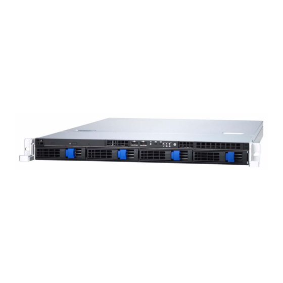
About the Product The following views show you the product. 1.4.1 Front View Reset NMI Switch Switch ID Switch Warning LED HDD Activity LED Power LED USB Ports CD-ROM Drive ID LED Power Switch 2x LAN LEDs Hard Drive Bay x 4 1.4.2 Rear View Power Supply Socket PS/2 Mouse/Keyboard Ports... -
Page 16: Led Definition
1.4.3 LED Definition Front Pane Color State Description Power Green Power ON Power OFF HDD Activity Amber Random Blink HDD access activity No disk activity LAN1/LAN2 Activity Green LAN linked Green Blinking LAN accessing No LAN linked Warning Fan fails Normal ID LED Blue... - Page 17 Rear I/O LED Color State Description RJ45 NIC1 Linkage Green LAN linked (Left Side) Green Blinking LAN accessing No LAN linked RJ45 NIC1 Mode Amber Gigabit mode (Right Side) Green 100M mode 10M mode RJ45 NIC2 Linkage Green LAN linked (Left Side) Green Blinking...
-
Page 18: Internal View
1.4.4 Internal View 1. PCI-X Slot 9. LED Control Board Cable 2. Link Bar 10. Four SATA HDDs 3. Memory Slots 11. Slim CD-ROM 4. EPS 12V Power Supply 12. CD-ROM Cable 5. CPU Socket 13. SATA Cables 6. System Fans (Left to right: FAN5, FAN4, FAN3, FAN2, FAN1) 7. -
Page 19: Motherboard (S5191) Block Diagram
1.4.5 Motherboard (S5191) Block Diagram Chapter 1: Overview... -
Page 20: Motherboard Layout
1.4.6 Motherboard Layout USBx2 LAN3 INTEL COM1 E7230 DDRII 4 LAN1 DDRII 3 DDRII 2 LAN2 DDRII 1 PCIX-E1 PCIX-E1 PCIX-P1 PCIX-P1 JP15 BIOS J 13 J 11 J 12 J 10 SMDC COM2 JP14 Chapter 1: Overview... - Page 21 Jumpers & Connectors Jumper Function /Connector COM2 Header J7/J9 Chassis Fan Connector SO-DIMM Socket J13/J14/J18 Front Fan Connector CPU Fan Connector J21/J22/J24/J25 Serial ATA RAID Connector JP1/JP2 SMDC/ASF2.0 Select Header LAN3 Enable/Disable Jumper PCI-X Speed Select Header JP7/JP9 Front Panel USB2.0 Connector JP14 SMDC Connector JP15...
- Page 22 Chapter 1: Overview...
-
Page 23: Chapter 2:Setting Up
Chapter 2: Setting Up 2.0.1 Before You Begin This chapter explains how to install the CPU, CPU heatsink, memory modules, and hard drives. Instructions on inserting a PCI-E card are also given. Take note of the precautions mentioned in this section when installing your system. -
Page 24: Precautions
Working on a system that is connected to a power supply can be extremely dangerous. Follow the guidelines below to avoid damage to the Tank GT20 or injury to yourself. • Ground yourself properly before removing the top cover of the system. -
Page 25: Rack Mounting
2.1.1 Installing the Server in a Rack Follow these instructions to mount the Tank GT20 into an industry standard 19" rack. NOTE: Before mounting the Tank GT20 in a rack, ensure that all internal components have been installed and that the unit has been fully tested. - Page 26 Installing the Inner Rails to Chassis 1. Screw the mounting ear to each side of Tank GT20 as shown using 2 screws from the supplied screws kit. Mounting Ears 2. Draw out the inner rails from rail assembly. Install inner rails to left and right sides of chassis using 2 M4-5L(D) screws for each side.
- Page 27 4. Locate the front and rear brackets. Rear Bracket x2 Front Bracket x2 5. Reserve 40mm on the front bracket. Secure the front bracket to outer rail with 2 M4-4L(C) screws. Chapter 2: Setting Up...
- Page 28 6. Reserve the distance same as in Step 2 on rear bracket. Secure the rear bracket to outer rail with 2 M4-4L(C) screws. 7. Secure the outer rail to the rack using 2 brackets and 4 M4-8L(E) screws for each side (A). Secure the mounting brackets from inside, not outside, of the rack (B).
- Page 29 Rackmounting the Server 8. Draw out the middle rail to the latch position. 9. Lift the chassis and then insert the inner slide rails into the middle rails. 10. Push the chassis in and press the latch key (A). Then push the whole system into the rack (B).
- Page 30 11. Secure the mounting ears of chassis to the rack with 2 M4-15L(F) screws. NOTE: To avoid injury, it is strongly recommended that two people lift the Tank GT20 into the place while a third person screws it to the rack. Chapter 2: Setting Up...
-
Page 31: Installing Motherboard Components
CPU, memory modules, and PCI card. 2.2.1 Removing the Chassis Cover Follow these instructions to remove the Tank GT20 chassis cover. 1. Release the screw on the back side. Then slide the chas- sis cover in the direction of arrow. -
Page 32: Installing The Cpu, Heatsink, And Air Duct
2.2.2 Installing the CPU, Heatsink, and Air Duct Follow these instructions to install the CPU, CPU heatsink, and air duct. 1. Release the pre-installed air duct. Locate the CPU socket. CPU socket 2. Remove the cover on the CPU socket cap. 3. - Page 33 4. Press and pull the lever in the direction as illustrated. 5. Open the socket in the direction as illustrated. 6. Place CPU on the socket, ensuring that the edge with tri- angle mark aims at the edge of socket with triangle mark. Chapter 2: Setting Up...
- Page 34 7. Close the cover and secure the CPU socket in the direc- tion shown. 8. Secure the heatsink with 4 screws. NOTE: Remember to install the washer and nut while install- ing the screws. 9. Secure the air duct with 2 screws. Chapter 2: Setting Up...
-
Page 35: Installing The Memory
2.2.3 Installing the Memory Follow these instructions to install the memory modules on the motherboard. 1. Locate the memory slots on the motherboard. 2. Press the memory slot locking levers in the direction of the arrows as shown in the following illustration. 3. -
Page 36: Installing The Pci Card
2.2.4 Installing the PCI Card Follow these instructions to install a PCI card. 1. Push the tab of PCI slot on the rear panel in the direction as shown to release the bracket. 2. Move the bracket to right as shown and then take off the bracket (A). -
Page 37: Installing The Hard Drive
Installing the Hard Drive The Tank GT20 barebone system supports Serial ATA hard drives. Follow these instructions to install a SATA hard drive. 1. Press the locking lever latch in the direction of arrow (A) and then pull the locking lever open (B). - Page 38 4. Using 4 HDD screws to secure the HDD. 5. Reinsert the drive tray into the chassis (A), ensuring that the drive tray is completely inserted into the chassis (B). 6. Pressing the locking lever to secure the hard drive tray. Chapter 2: Setting Up...
-
Page 39: Installing The Slim Fdd (Option)
Installing the Slim FDD (Option) 1. Locate the two FDD rails and screws from the FDD kit. Secure the two rails to FDD using four screws. FDD Rails & Screws 2. Connect the FFC cable to FDD. 3. Use a screw driver to take off the door of FDD tray. 4. - Page 40 5. Connect the FFC cable to the FDD connector on M1012 adapter board. 6. Locate the FDD cable from FDD kit. Connect the wrinkle side to the connector on M1012 adapter board. Refer to the picture below for the correct direction. For Mainboard For M1012 7.
-
Page 41: Chapter 3:Replacing Pre-Installed Components
Chapter 3: Replacing Pre-Installed Components Introduction This chapter explains how to replace pre installed compo- nents including the motherboard, LED control board, HDD, and CD-ROM drive. Take note of the precautions in this section when installing your system. 3.1.1 Work Area Make sure you have a stable, clean working environment. -
Page 42: Precautions
Components and electronic circuit boards can be damaged by static electricity. Working on a system that is connected to a power supply can be extremely dangerous. Follow the guidelines below to avoid damage to the Tank GT20 or injury to yourself. •... -
Page 43: Disassembly Flowchart
Disassembly Flowchart The following flowchart outlines the disassembly procedure. Rear Components DIMMs Chassis rear cover CPU/heatsink assembly Air duct PCI card Mainboard Mainboard Power supply Front Components Chassis rear cover PCBs CD-ROM M1012 Control Adapter Board Board Backplane Chapter 3: Replacing Pre-Installed Components... -
Page 44: Removing The Cover
Removing the Cover Before replacing any parts you must remove the chassis cover. Follow these instructions to remove the Tank GT20 chassis cover. 1. Release the screw on the back side. Then slide the chas- sis cover in the direction of arrow. -
Page 45: Replacing Motherboard Components
Replacing Motherboard Components Follow these instructions to replace motherboard compo- nents, including the motherboard. 3.4.1 Disconnecting All Motherboard Cables Before replacing the motherboard or certain components, remove cables connected to the motherboard. Follow these instructions to remove all motherboard cabling. 1. -
Page 46: Removing The Motherboard
3.4.2 Removing the Motherboard Follow these instructions to remove the motherboard from the chassis when all add-on components have been removed. 1. Release the two screws securing the link bar. 2. Remove the link bar. 3. Remove the eleven screws securing the motherboard to the chassis. -
Page 47: Replacing The Led Control Board
Replacing the LED Control Board Follow these instructions to remove the LED control board. 1. Remove the 2 screws securing the LED control board to the chassis. 2. Pull the LED control board free from the chassis and unplug the ribbon and USB cables from the connector. 3. - Page 48 4. Release the LED control board from the chassis. After replacement, insert and secure the unit to the chassis fol- lowing the reverse procedures from step 1~3. Chapter 3: Replacing Pre-Installed Components...
-
Page 49: Replacing The M1012 Adapter Board
Replacing the M1012 Adapter Board 1. Before replacing M1012 adapter board, you must discon- nect the four SATA cables connected to the SATA back- plane. After that, disconnect all the cables connected to the M1012 adapter board. CD-ROM Power Cable SATA Cables 2. - Page 50 4. Remove one power cable connected to M1012 adapter board and two power cables connected to SATA back- plane. 2x power cables on SATA backplane 1x power cable on M1012 5. Remove the 6 screws securing the M1012 adapter board. After that, you can release the M1012 adapter board from the chassis.
-
Page 51: M1012 Adapter Board Features
3.6.1 M1012 Adapter Board Features J1: Front Panel Connector J16: LCM Connector FDD1: Standard J14: Fan Tach Connector Floppy Connector J7:Fan Tach & PWM Connector J3: LAN/ID LED Connector JP1: Fan Input Select Connector J19: CD-ROM Power Connector J5: Fan Connector J9: Fan Connector J11: Fan Connector J10: Fan Connector... -
Page 52: M1012 Adapter Board Connector Pin Definition
3.6.2 M1012 Adapter Board Connector Pin Definition J1 TYFP Front Panel Connector HDLED+ PW_LED+ HDLED- PW_LED - RESET- PWR_SW+ RESET+ PWR_SW - VOLTAGE5 WLED+ EXT_INT WLED- V5SB KEY PIN ICH_SMBDAT ICH_SMBCLK INTRU# J2 Front Panel Connector HDLED+ HDLED- RESET+ RESET- PW_LED+ PW_LED- WLED+... - Page 53 J3 LAN/ID LED Connector LAN1_LED+ LAN1_LED- LAN2_LED+ LAN2_LED- LAN3_LED+ LAN3_LED- ID_LED+ ID_LED- ID_SW+ ID_SW- KEY PIN FAN Signal Related Connector Pin Definition NOTE: The FAN signal naming is based on HW circuit design only. It might be different from the system fan naming. J4 Fan TACH &...
- Page 54 J13 Fan TACH Connector FAN1_TACH FAN2_TACH FAN3_TACH KEY PIN J14 Fan TACH Connector FAN1_TACH FAN2_TACH FAN3_TACH FAN4_TACH FAN5_TACH FAN6_TACH FAN7_TACH FAN8_TACH FAN9_TACH FAN10_TACH KEY PIN J6 Fan Connector FAN1_12VPWM FAN1_TACH FAN2_TACH FAN2_12VPWM Chapter 3: Replacing Pre-Installed Components...
- Page 55 J10 Fan Connector FAN3_12VPWM FAN3_TACH FAN4_TACH FAN4_12VPWM J11 Fan Connector FAN5_12VPWM FAN5_TACH FAN6_TACH FAN6_12VPWM J9 Fan Connector FAN7_12VPWM FAN7_TACH FAN8_TACH FAN8_12VPWM Chapter 3: Replacing Pre-Installed Components...
- Page 56 J5 Fan Connector FAN9_12VPWM FAN9_TACH FAN10_TACH FAN10_12VPWM J15 & J16 LCM Connectors LCM_+5V LCM_SIN KEY PIN LCM_+5VSB LCM_SOUT JP1 Fan Input Select Connector Pin1 & Pin2 Close Fan PWM signal from J8 Pin2 & Pin3 Close Fan PWM signal from J4, J7 &...
-
Page 57: Replacing The Sata Backplane
Replacing the SATA Backplane 1. After removing the M1012 adapter board, you can easily grab the two lables to lift the SATA backplane. 2. Remove the ten screws that secure the bracket to the backplane. 3. Release the backplane free from the bracket. 4. -
Page 58: S-Ata Backplane (M1208) Features
3.7.1 S-ATA Backplane (M1208) Features U4, SATA 4 Connector U3, SATA 3 Connector U2, SATA 2 Connector HDD Power LED HDD Active LED U1, SATA 1 Connector Chapter 3: Replacing Pre-Installed Components... - Page 59 PW1 Power Connector PW2 Power Connector J4, SATA 4 Connector J3, SATA 3 Connector J2, SATA 2 Connector J1, SATA 1 Connector Chapter 3: Replacing Pre-Installed Components...
-
Page 60: Replacing The Cooling Fan
Replacing the Cooling Fan Follow these instructions to replace the cooling fans in your system. 1. Locate the fan connector on the motherboard and unplug the fan cable. 2. Take the fan away from the chassis. 3. Replace the fan into the chassis following the reverse procedures from 1 to 2 after done. -
Page 61: Replacing The Power Supply
Replacing the Power Supply 1. Remove the two screws that secure the power supply to the chassis. 2. Remove the screw that secure the fan assembly to the chassis Chapter 3: Replacing Pre-Installed Components... - Page 62 Chapter 3: Replacing Pre-Installed Components...
-
Page 63: Appendix I: Bios Differences
Appendix I: BIOS Differences The BIOS of B5191 is similar to S5191 while there are some menus different. The following table displays the differences in BIOS between B5191 and S5191. For a complete review of S5191 BIOS, refer to the motherboard manual. Difference 1: S5191 Advanced/Hardware Monitoring PhoenixBIOS Setup Utility... - Page 64 Difference 2: S5191 Advanced/Hardware Monitoring/FAN Control PhoenixBIOS Setup Utility Advanced FAN Control Sub-Menu Item Specific Help Auto Fan Control [Disabled] Auto Mode Fan Control Parameters CPU FAN Input type select [4 PIN] FAN1 Input type select [4 PIN] FAN2 Input type select [4 PIN] FAN3 Input type select [4 PIN]...
-
Page 65: Appendix Ii: Cable Connection Tables
Appendix II: Cable Connection Tables SATA Cable Table 1: B5191G20S4H Model M1208 SATA Backplane Connect to Motherboard SATA 1 SATA 1 (J21) SATA 2 SATA 2 (J24) SATA 3 SATA 3 (J22) SATA 4 SATA 4 (J25) FAN Cable Table 2: System Fan to M1012 Adapter Board System Fan Connect to M1012... - Page 66 Power Supply Cable Table 4: Power Supply to Motherboard Power Supply Connect to Motherboard P1 24-pin power cable PW1 24-pin connector P2 8-pin power cable PW2 8-pin connector Table 5: Power Supply to M1012 Adapter Board Power Supply Connect to M1012 P3 4-pin power cable PW2 4-pin connector...
- Page 67 Table 10: Chassis Intrusion Cable Chassis intrusion switch Motherboard JP15 Pin 16 & Pin 18 Table 11: FDD Related Cable (Option) M1012 FDD1 connector Motherboard J5 FDD M1012 FDD2 connector Slim FDD drive...
-
Page 68: Appendix Iii: Installing Smdc Cards
Appendix III: Installing SMDC Cards The following provides you with the information on installing SMDC cards. You may refer to the following for installing M3289 or M3290 into HDD tray or chassis. Screws List (including screws for Rail) A: Flat 6#-32 x4~x16 B: B-type 6#-32 x4 C: M4-4L x8 D: M4-5L x4... - Page 69 Installing M3289 into HDD Tray 1. Fold up the cable. 2. a: Choose a HDD tray. b: Insert the cable into the rear of HDD tray. c: Pull the cable out. 3. Connect the cable to M3289.
- Page 70 4. Align M3289 in reverse with 4 “M1” stand-offs. Secure the SMDC with 4 screws as illustrated. 5. Secure M3289 onto HDD tray as illustrated. 6. Insert and secure the HDD tray. NOTE: For internal or dummy HDD tray, secure the HDD tray with 1 or 2 screws.
- Page 71 Installing M3290/M3291 into HDD tray 1. Secure a removable stand-off of 13.5mm to the location of “M2” stand-off as illustrated on SMDC bracket. 2. Secure M3290 in reverse to 4 “M2” stand-offs on bracket. 3. a: Choose a HDD tray. NOTE: Refer to the location of SMDC connector on mainboard for choosing a HDD tray.
- Page 72 4. a: Inset the cable into the rear of HDD tray. b: Connect the cable to M3290. c: Insert and secure HDD tray. 5. Arrange and connect the cable to SMDC connector on mainboard. Be careful not to block the air flow. Installing M3290/M3291 into GT20 Chassis NOTE: The products produced now may not support the pro- cedures below.
- Page 73 3. Align M3290 with 4 “M2” PC stand-offs. Secure M3290 to mainboard with 4 screws. 4. Connect the cable to M3290. Arrange and connect the cable to SMDC connector on mainboard. Be careful not to block the air flow. 5. Reconnect the power connectors on HDD backplane and M1012.
-
Page 74: Technical Support
(which can have expensive consequences). If these options are not available for you then Tyan Computer Corporation can help.Besides designing innovative and qual- ity products for over a decade, Tyan has continuously offered customers service beyond their expectations. - Page 75 RMA number should be prominently displayed on the outside of the shipping carton and the package should be mailed pre- paid. TYAN will pay to have the board shipped back to you. B5191, Service Engineer’s Manual v1.0 Document part No. D1755-100...
Need help?
Do you have a question about the Tank GT20 and is the answer not in the manual?
Questions and answers