
Related Manuals for Grunbeck desaliQ


Summary of Contents for Grunbeck desaliQ
- Page 1 We understand water. Heating water treatment system | desaliQ inline control module Operation manual...
- Page 2 General Contact Germany Phone +49 9074 41-0 Fax +49 9074 41-120 Availability Monday to Thursday 7:00 am - 6:00 pm Friday 7:00 am - 12:00 We reserve the right to technical modifications. © by Grünbeck Wasseraufbereitung GmbH Original operation manual Edition: July 2022 Order-no.: 100093670000_en_065...
-
Page 3: Table Of Contents
Table of contents Table of contents Operation/handling ......42 Table of contents ........... 3 Operation of the control unit ....42 Introduction .......... 4 Program selection and sequence ..46 Resetting the water meter ....55 Validity of the manual ......4 Changing the basic settings .... -
Page 4: Introduction
1.1 Validity of the manual This manual applies to the products below: ● desaliQ inline control module ● desaliQ inline control module (country-specific version for Switzerland, Denmark and Uruguay) 1.2 Other applicable documents ● Operation manual of mixed bed cartridge desaliQ:MB9 ●... -
Page 5: Product Identification
Introduction 1.3 Product identification You can identify your product based on the product designation and the order no. shown on the type plate. ► Check whether the products given in chapter 1.1 corre- spond to your product. The type plate is located on the device. Item Designation Item... -
Page 6: Symbols Used
Introduction 1.4 Symbols used Symbol Meaning Danger and risk Important information or requirement Useful information or tip Written documentation required Reference to further documents Work that must be carried out by qualified special- ists only Work that must be carried out by qualified electri- cians only Work that must be carried out by technical service personnel only... -
Page 7: Demands On Personnel
Introduction The following signal words are defined subject to the degree of danger and might be used in the present document: Warning symbol Consequences if the infor- and signal word mation/instructions are ignored DANGER Death or serious injuries Possible death or serious WARNING injuries Possible moderate or minor... - Page 8 Introduction 1.6.1 Qualification of personnel Personnel Requirements • Operator/user No special expertise required • Knowledge of the tasks assigned • Knowledge of possible dangers in case of incorrect behaviour • Knowledge of necessary protective equipment and protective measures • Knowledge of residual risks •...
- Page 9 Introduction 1.6.2 Authorisations of personnel The table below specifies which tasks may be carried out by whom. Transport and storage Installation and mounting Start-up Operation and handling Cleaning Inspection Maintenance Troubleshooting Repair Decommissioning and restart/ recommissioning Dismantling and disposal 1.6.3 Personal protective equipment ►...
-
Page 10: Safety
Safety Safety 2.1 Safety measures ● Only use genuine spare parts for maintenance or repair. ● Risk of burns due to hot surfaces on lines and components as well as due to escaping heating water. Let the product cool down to at least 30 °C before carrying out any repair and maintenance work. - Page 11 Safety 2.1.2 Pressure-related hazards ● Components can be under pressure. There is a risk of inju- ries and damage to property due to escaping water and un- expected movement of components. ● Before starting repair and maintenance work, make sure that all affected components are depressurised.
-
Page 12: Product-Specific Safety Instructions
Safety 2.1.4 Groups of persons requiring protection ● This product is not designed to be used by persons (includ- ing children) with reduced capabilities, lack of experience or lack of knowledge. ● Children should be supervised to make sure that they do not play with the product. -
Page 13: Conduct In Emergencies
Safety NOTE Inhibitors contained in the heating circuit ● If inhibitors were added to the heating water, these will be removed by the resin of the softening or mixed bed car- tridge. ► Carry out the filter operation only. ► Check the concentration of the inhibitor during softening and demineralisation operation. -
Page 14: Product Description
3.1.1 Foreseeable misuse ● The desaliQ inline control module must not be used for the treatment of raw water that is to be used as drinking water. 14 | 80... -
Page 15: Product Components
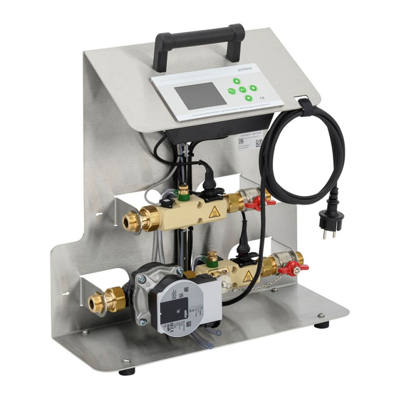
Product description 3.2 Product components Item Designation Item Designation Console Carrying handle Key-operated control panel Cable holder Mains cable with Schuko plug Conductivity sensor (pure water) Inlet shut-off valve Combined block of (pure water) sensor section Conductivity sensor Outlet shut-off valve (heating (heating water) water to mixed bed cartridge) Valve for venting/sampling... - Page 16 Product description 3.2.1 Version for Switzerland Instead of the Schuko mains plug, a country-specific mains plug is supplied. Illustration Product Mains plug for Switzerland 3.2.2 Version for Denmark Instead of the Schuko mains plug, a country-specific mains plug is supplied. Illustration Product Mains plug for Denmark...
-
Page 17: Functional Description
Product description 3.3 Functional description The function of the desaliQ inline control module is based on the well-proven processes of filtration and softening or demineralisa- tion. The desaliQ inline control module is integrated into the filled heat- ing or cooling circuit in the partial flow. Part of the circulation wa- ter permanently flows through the desaliQ inline control module. - Page 18 In combination with the desaliQ inline filter module, undissolved impurities such as rust and dirt particles are filtered from the heat- ing water. Demineralisation In combination with the desaliQ resin bags, the heating water is fully demineralised. Softening In combination with the softening cartridge decaliQ, the heating water is softened according to the ion exchange principle.
-
Page 19: Accessories
Product description 3.4 Accessories Your product can be retrofitted with accessories. Please contact your local Grünbeck representative or Grünbeck’s headquarters in Hoechstaedt/Germany for details. Illustration Product Order no. Hose kit DN 20, straight/straight 707 840 Consisting of: 2 hoses of 1.5 m in length with straight connections, 2 double nipples, including seals Hose kit DN 20, straight/90°... -
Page 20: Transport And Storage
Transport and storage Transport and storage 4.1 Transport ► Transport the product in its original packaging only. ► Do not discard the packaging. Use the packaging for transport between uses. NOTE Residual water in the device after use. ● In the event of frost, the remaining, freezing residual wa- ter in the device can damage the components beyond re- pair. -
Page 21: Installation
Item Designation Outlet of desaliQ:MB9 Mixed bed cartridge (filtered heating water) desaliQ:MB9 desaliQ resin bags desaliQ inline filter module Inlet to desaliQ:MB9 Connection from heating (heating water) circuit (pump section) Connection to heating circuit Return of heating circuit (sensor section) - Page 22 Safety device protectliQ Drinking water filter pureliQ Water softener softliQ System separator BA (filling group thermailQ:SB13) Treatment group thermaliQ filling pump for thermaliQ:HB2 dosing solution for heating protection GENO-therm sludge Mixed bed cartridge separator desaliQ:MB9 desaliQ inline control module 22 | 80...
- Page 23 Drinking water filter pureliQ Water softener softliQ System separator BA (filling group thermailQ:SB13) Treatment group thermaliQ filling pump for thermaliQ:HB2 dosing solution for heating with connection adapter protection GENO-therm sludge Mixed bed cartridge separator desaliQ:MB9 desaliQ inline control module 23 | 80...
- Page 24 Installation The desaliQ inline control module is integrated in the return of the heating circuit. In order to ensure the proper operation of the desaliQ inline control module, respect the points below: ● In order to be able to treat the entire content of the circuit, it must be completely circulated.
-
Page 25: Requirements For The Installation Site
Installation 5.1 Requirements for the installation site Obey the local installation directives, general guidelines and tech- nical specifications. ● The installation site must be frost-proof and protect the product from direct sunlight, chemicals, dyes, solvents and their vapours. ● The installation room must have a floor drain. If no floor drain is available, an appropriate safety device must be installed. -
Page 26: Checking The Scope Of Supply
The cardboard box simultaneously is intended for safe transport and proper storage between uses (refer to chapter 4) Item Designation Item Designation desaliQ inline control module Operation manual Seal kit Fastening material for wall (5x flat seal, 5x sieve seal) mounting ►... -
Page 27: Water Installation
Installation 5.3 Water installation Obey the operation manuals below: • Mixed bed cartridge desaliQ:MB9 • desaliQ inline filter module • Softening cartridge decaliQ The temperature range is subject to the maxi- NOTE mum admissible operating temperature of the cartridge. ● Risk of damaging the cartridge if the max. admissible op- erating temperature is exceeded. - Page 28 Installation Mixed bed cartridge desaliQ:MB9 Item Designation Item Designation Hose connection Mixed bed cartridge de- saliQ:MB9 Inlet (heating water) desaliQ inline filter module desaliQ resin bags Hose connection Outlet (pure water) 28 | 80...
- Page 29 Installation Softening cartridge decaliQ:BA12/BA16 VARIO mini Item Designation Item Designation Hose connection Softening cartridge decaliQ (decaliQ:BA12 or Inlet (heating water) decaliQ:BA16) Hose connection Outlet (softened heating water) In order to increase the demineralisation or softening capacity, several cartridges can be connected in series. 29 | 80...
- Page 30 Designation desaliQ inline control module mounted on the wall in a stationary position You can mount the console of the desaliQ inline control module on the wall using the fastening material supplied with the sys- tem. The fastening material supplied with the system is suitable for concrete and solid bricks.
- Page 31 Installation ► Mark the drill holes according to the drilling diagram below: 1. Drill the holes and insert the dowels. Item Designation Item Designation Spacers Hanger bolts M8x80 31 | 80...
- Page 32 Installation 2. Screw in the hanger bolts. 3. Slide the spacers onto the hanger bolts. 4. Hang the console on the hanger bolts. 5. Level the console with the help of a spirit level and fix it with the nuts. 6.
- Page 33 Installation 5.3.2 Installing the connection hoses The connection hoses must be selected and laid according to the respective situation on site (refer to chapter 3.4). All connec- tion hoses must be secured against water leaks by means of a seal. Sharp thread and pinching points on connec- CAUTION tions...
- Page 34 Installation 5.3.2.1 Connecting the mixed bed cartridge/softening cartridge Item Designation Item Designation Connection hose ¾" Connection hose ¾" to the cartridge from the cartridge 1. Mount the connection hoses on the connections: Inlet to cartridge and outlet from cartridge 2. Mount the connection hoses on the cartridge Obey the respective operation manual of the mixed bed car- tridge or the softening cartridge.
- Page 35 Installation 5.3.2.2 Connecting the heating circuit Item Designation Item Designation Connection hose ¾" Connection hose ¾" Inlet from the heating circuit Outlet to the heating circuit (pump section) (sensor section) Sieve seal ¾" (included in the seal kit) 1. Mount the connection hose on the inlet connection of the heating circuit.
- Page 36 Installation 5.3.2.3 Connecting the make-up water connection Via the make-up water connection, you can feed water into the heating system during circulation water treatment. System sep- aration according to DIN EN 1717 is required. Item Designation Item Designation Filling group ther- Connection of the drinking wa- maliQ:SB13 or Euro system ter supply line...
-
Page 37: Start-Up
Escaping hot circulation water in case of heating WARNING systems that are already in operation ● Scalding ► Do not vent the desaliQ inline control module under any circumstances by opening a screw connection. ► Use protective gloves. 6.1.1 Preliminary activities 1. - Page 38 Mains cable, 3 m in length bed cartridge 1. Open the on-site shut-off valve of the heating water inlet to the desaliQ inline control module. 2. Open the outlet shut-off valve (heating water). 3. Open the shut-off valve on the mixed bed cartridge.
- Page 39 Start-up 6.1.2 Venting Only a system that has been fully vented works without major noise emission. NOTE Escaping leakage or heating water. ● The circulation pump can be damaged. ► When venting, use a container to collect the escaping liq- uid.
- Page 40 Start-up 6.1.3 Checking for leaks 1. Visually check all connections on the device and on the en- tire system for leaks. » No leakage water must escape. 6.1.4 Starting up the product 1. Loosen the cable holder and unwind the mains cable. 2.
- Page 41 Start-up Setting the control unit 1. During the initial start-up, set the language and hardness unit in the control unit (refer to chapter 7.1). 2. Obey the instructions given in the control unit. 41 | 80...
-
Page 42: Operation/Handling
An acoustic buzzer is activated in the event of a success or fault signal. The respective signal is repeated three times at intervals. The signal intervals can be deactivated by confirming the signal. ► Obey the instructions in the display of the desaliQ inline control module. 42 | 80... - Page 43 Operation/handling 7.1.1 Control panel Designation Meaning/Function • To read off the current values Display • Going back Operating • Quitting the menu • Saving a parameter Operating • Aborting or confirming/starting a program step • Setting values • Decreasing the numerical value of a Operating parameter •...
- Page 44 Operation/handling 7.1.2 Display Designation Meaning/Function Home • Basic display for current values Menu display • Green = selectable, inactive level • Orange = active level Menu display Program selection Water meter • Current value Menu display • Resetting the meter Technical service Menu display •...
- Page 45 Operation/handling 7.1.3 Signals Illustration Meaning/Function Information (green) • Program completed successfully Information with exclamation mark (orange) • Program completed; goal not reached, however • Aborting program Warning signal (red) • Program interrupted Fault signal (red) • Program aborted 7.1.4 Basic display Home In the basic display Home, current values are displayed Item Designation...
-
Page 46: Program Selection And Sequence
Operation/handling 7.2 Program selection and sequence ► Select the required operating mode in the menu: ● Treatment (refer to chapter 7.2.1). • Filtration, demineralisation, softening ● Filling (refer to chapter 7.2.3). • Demineralisation, softening ► Follow the instructions in the control unit. The duration of the operation depends on the degree of impuri- ties, the volume and the hydraulic conditions in the heating circuit. - Page 47 Operation/handling You can manually abort a started program by pressing the enter In the event of a warning signal , you can continue or abort the program after the malfunction has been rectified. In case of a fault signal , you can interrupt or abort the pro- gram.
- Page 48 Designation Item Designation Treatment time desaliQ inline filter module 1. Set the Treatment time. 2. Start the filter operation. 3. Take samples from the heating circuit at regular intervals in order to check whether the filter operation can be termi- nated.
- Page 49 Operation/handling 7.2.1.2 Demineralisation Any inhibitors possibly present in the heating circuit can be re- moved by the resin of the cartridge. ► After the demineralisation operation, re-establish the re- quired inhibitor concentration. The duration of the demineralisation operation depends on the existing conductivity, the target conductivity, the volume and the hydraulic conditions in the heating circuit and in general takes a few hours up to several days.
- Page 50 Operation/handling 7.2.1.3 Softening Any inhibitors possibly present in the heating circuit can be re- moved by the resin of the cartridge. ► After the softening operation, re-establish the required in- hibitor concentration. The duration of the softening operation depends on the existing hardness, the target hardness, the volume and the hydraulic con- ditions in the heating circuit and in general takes a few hours up to several days.
- Page 51 Operation/handling 7.2.2 Taking samples As the desaliQ inline control module is connected in the partial flow, sampling must take place at regular intervals in order to check the progress of the treatment. During sampling, the entire system volume of the heating circuit must be in motion.
- Page 52 Operation/handling 5. Take the water sample at the pure water valve downstream of the cartridge. 6. Either measure the pH value and the hardness of the heat- ing water or the pH value and the conductivity. ► Compare the measured values with the requirements of VDI 2035 and the specifications of the manufacturers of the circuit components.
- Page 53 Operation/handling 7.2.3.1 Demineralisation Item Designation Item Designation Conductivity limit value at the Program symbol cartridge outlet Demineralisation 1. Close the shut-off valve for the heating circuit on the de- saliQ inline control module. 2. Reset the Water meter. 3. Set the Conductivity limit value at the cartridge outlet. 4.
- Page 54 Operation/handling 7.2.3.2 Softening Item Designation Item Designation Program symbol Softening Capacity figure of cartridge Raw water hardness 1. Close the shut-off valve for the heating circuit on the de- saliQ inline control module. 2. Reset the Water meter. 3. Set the Raw water hardness. 4.
-
Page 55: Resetting The Water Meter
Operation/handling 7.3 Resetting the water meter You can reset the water meter at any time, e.g. after the program has been completed. 1. Select the water meter menu » The current value is displayed. 2. Reset the meter with Yes. 7.4 Changing the basic settings In the code-protected area, you can change the basic settings. -
Page 56: Calibrating The Conductivity Sensors
Operation/handling 7.4.2 Code 245 ► Read the system information: ● Total water volume ● Temperature of circuit board 7.5 Calibrating the conductivity sensors The work below must be carried out by a qualified specialist only. In Code 121, you can recalibrate the temperature sensor, the conductivity sensor 1 and the conductivity sensor 2. - Page 57 Operation/handling NOTE Do not crush the cable ● When tilting the device, the cable may be crushed under the device and damaged. ► When tipping the device over, take care to guide the cable – do not place it under the console. ►...
- Page 58 Operation/handling Item Designation Item Designation Temperature sensor Conductivity sensor 1 (inlet) Calibration solution Conductivity sensor 2 Conductivity LF 1413 µS/cm (outlet) (order no. 203 624) ► Drain the device completely. ► Clean the conductivity sensor, if required (refer to chapter Fehler! Verweisquelle konnte nicht gefunden wer- den.).
- Page 59 Operation/handling 7.5.1.2 Calibrating the conductivity sensors You need two bottles of calibration solution (order no.: 203 624). The conductivity sensors 1 and 2 are calibrated in sequence. Conductivity sensor 1 (inlet) ► Tilt the device to the left. 1. Fill 1 bottle of calibration solution (50 ml) into the opening of the pump section –...
- Page 60 Operation/handling Conductivity sensor 2 (outlet) ► Tilt the device to the right. ► Close the ball valve of the sensor section. 1. Fill 1 bottle of calibration solution (50 ml) into the connec- tion flap opening of the sensor section. »...
- Page 61 Operation/handling Final work 1. Completely rinse the pump section and the sensor section with water. a Make sure the device is vented. 2. Check the conductivity value – it must match the flushing water. » The device is recalibrated. In case of wall mounting: 1.
-
Page 62: Maintenance And Repair
Maintenance and repair Maintenance and repair Maintenance and repair includes cleaning, inspection and mainte- nance of the product. The responsibility for inspection and maintenance is subject to local and national requirements. The owner/operating company is responsible for compliance with the prescribed maintenance and repair work. -
Page 63: Intervals
Maintenance and repair ► Wipe the surfaces with a damp cloth. ► Flush the device with clear water after every use (refer to chapter 10). 8.2 Intervals By way of regular inspections and maintenance, malfunctions can be detected in time and product failures might be pre- vented. -
Page 64: Inspection
Maintenance and repair 8.3 Inspection You as owner/operating company can do the regular inspections yourself. ► Carry out an inspection at least every 6 months and pro- ceed as follows to do so: 1. Check all water-carrying parts for leaks. 2. -
Page 65: Maintenance
Maintenance and repair 8.4 Maintenance In order to ensure the proper functioning of the product in the long term, certain tasks have to be performed at regular intervals. Life-threatening voltage on electrical compo- WARNING nents ● Severe burns, cardiovascular failure, fatal electric shock. ●... - Page 66 Maintenance and repair 8.4.1 Cleaning the conductivity sensors ► Proceed as follows to clean both of the conductivity sensors: Item Designation Item Designation Conductivity sensor Retaining clip 1. Pull out the retaining clip. 2. Pull out the conductivity sensor. 3. Clean the conductivity sensor with drinking water. a Dry the conductivity sensor.
-
Page 67: Spare Parts
Maintenance and repair 8.4.2 Checking the circulation pump 1. Clean the circulation pump with a dry cloth. 2. Check the circulation pump for function. 3. Check the plug for tight fit. ► Check all electric lines for damage. ► Replace damaged components. 8.5 Spare parts For an overview of the spare parts, refer to our spare parts cata- logue at www.gruenbeck.com. -
Page 68: Troubleshooting
Troubleshooting Troubleshooting 9.1 Messages 1. Eliminate the fault (refer to fault table). 2. Acknowledge the fault. 3. Monitor the display of the control unit. 4. If the malfunction reoccurs, compare the display message with the fault table below. Display Explanation Remedy ►... -
Page 69: Other Observations
Troubleshooting 9.2 Other observations Observation Explanation Remedy ► Check fuses Circulation pump does Electrical fuse defective not run with power on ► Contact technical service ► Eliminate voltage in- No voltage applied terruption ► Increase system Circulation pump makes Cavitation due to insuffi- noises cient supply pressure pressure within the... -
Page 70: Decommissioning
10 Decommissioning Between uses, the desaliQ inline control module must be taken out of operation and stored temporarily. ► Proceed as follows to take the desaliQ inline control mod- ule out of operation: 1. Flush the device with clear water. -
Page 71: Disposal
Disposal 11 Disposal ► Obey the applicable national regulations. Packaging ► Dispose of the packaging in an environmentally sound manner. Product If this symbol (crossed-out wheelie bin) is on the product the product or its electrical and electronic components must not be disposed of as household waste. -
Page 72: Technical Specifications
Technical specifications 12 Technical specifications Dimensions and weights Height Depth Width Connection height of pump section Connection height of sensor section Connection depth of pump and sensor section Weight ~ 9.3 72 | 80... - Page 73 230/50 - 60 Rated power (operation) Performance data Nominal pressure 1.5 – 4 Operating pressure (circuit) Flow at Δp 1 bar (in combination with desaliQ:MB9) Nominal flow (in combination with desaliQ:MB9) General data 5 – 80 Water temperature °C 5 – 40 Ambient temperature °C...
-
Page 74: Operation Log
Operation log 13 Operation log ► Document the initial start-up/commissioning and all maintenance activities. desaliQ inline control module Serial no.: ___________________ 13.1 Start-up/Commissioning log Customer Name: Address: Installation/Accessories Remarks Start-up Installer/Owner/Operating company: Company: Work time certificate (no.): Date/signature: 74 | 80... -
Page 75: Maintenance
Operation log 13.2 Maintenance Work performed ☐ Inspection ☐ Maintenance ☐ Repair Description Execution confirmed Company: Name: Date: Signature: Work performed ☐ Inspection ☐ Maintenance ☐ Repair Description Execution confirmed Company: Name: Date: Signature: 75 | 80... - Page 76 Operation log Work performed ☐ Inspection ☐ Maintenance ☐ Repair Description Execution confirmed Company: Name: Date: Signature: Work performed ☐ Inspection ☐ Maintenance ☐ Repair Description Execution confirmed Company: Name: Date: Signature: 76 | 80...
- Page 77 This certificate becomes void if the system is modified in any way not approved by us. Heating water treatment system desaliQ inline control module Serial no.: Refer to type plate The aforementioned system also complies with the directives and provisions below: •...
- Page 79 Publisher's information Technical documentation Should you have any questions or suggestions regarding this operation manual, please contact Grünbeck Wasseraufberei- tung GmbH’s Department for Technical Documentation directly. Email: dokumentation@gruenbeck.de...
- Page 80 Grünbeck Wasseraufbereitung GmbH Josef-Grünbeck-Str. 1 89420 Hoechstaedt GERMANY +49 9074 41-0 +49 9074 41-100 info@gruenbeck.com For more information go www.gruenbeck.com to www.gruenbeck.com...
Need help?
Do you have a question about the desaliQ and is the answer not in the manual?
Questions and answers