Advertisement
—— Installation and Safe Use Manual ——
SVB5000A, SVB5050A
Match Point Outdoor Volleyball Systems
P A R T S L I S T
Item
Qty
Description
A
1
Winch Standard
B
1
Non-Winch Standard
C
2
SVB210 Ground Socket (Optional)
D
1
VB1250KU Net (Order SVB1250K for 2x2 competition)
E
4
Rope Ratchet Tensioner
Inspect all contents prior to installation. Report any missing parts to dealer immediately.
¨
Read all instructions before proceeding.
¨
This system can be adjusted from 7' 11 5/8" men's volleyball height to 45" tennis height.
¨
1. Layout your court. See Figure 7.
2 For permanent installation dig two holes 12" in diameter,
52" - 56" below the finish playing surface and 37 feet
apart (32 feet apart for 2x2 Competition). You will need
8-10 1/3 cubic foot bags of pre-mix concrete for each
hole. Insert Winch Standards (A) and Non-Winch
Standards (B). with the slider bars facing the center of
the court. Fill holes with concrete. The top of the two
Standards (A) and (B) need to be approximately 100"
above the final playing surface. The top surface of the
concrete footing needs to be 4" - 6" below the playing
surface of the sand if installing a sand court. Angling the
poles outward 1 1/2 - 2 degrees will offset the bend
caused by tensioning the net. Brace poles while concrete
cures. Make sure concrete has cured at least 7 days
before continuing with the installation. See Figure 1.
3. For removable installation push back the sand (if a sand court) at each standard location enough to
facilitate digging a 12" minimum diameter hole that is at least 60" deep from the theoretical finish grade of
the sand playing surface.
4. Fill the bottom 10" - 12" of the hole with premixed concrete.
5. Center the SVB210 Ground Sockets (C) in the hole after making sure that the plastic bottom cap is securely
attached. Push the sleeve to the depth where the top of the sleeve will be below the theoretical finish grade
of the sand approximately 4" if installing a sand court. Failure to follow this instruction will leave a
dangerous protrusion from the sand if the posts are removed and the sand is used for other activities.
Implementation Date: 4/5/23
Rev: 7
N.J.C.
1
SVB500A
Item
Qty
Description
F
2
Height Label
G
2
Post Padding (SVB5000A only)
H
2
Antennae (SVB5000A only)
I
1
SVB500 Court Adder (optional)
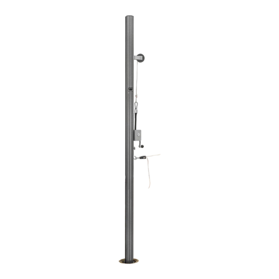
FIGURE 1
File: \96\SVB50A.pub
Customer Service
(800) 247-7668
Ref#: 960074
L.M.
Advertisement
Table of Contents

Subscribe to Our Youtube Channel
Related Manuals for Bison SVB5000A


Summary of Contents for Bison SVB5000A
- Page 1 Description Item Description Winch Standard Height Label Non-Winch Standard Post Padding (SVB5000A only) SVB210 Ground Socket (Optional) Antennae (SVB5000A only) VB1250KU Net (Order SVB1250K for 2x2 competition) SVB500 Court Adder (optional) Rope Ratchet Tensioner Inspect all contents prior to installation. Report any missing parts to dealer immediately.
- Page 2 Caution! The VB1250KU Net (D) is designed to fit Bison Match Point Systems by customizing the length of the top and bottom ropes. Tie a loop in one end of the top rope at a location that allows proper tensioning. Do Not cut the excess rope until you are confident you have the correct length.
- Page 3 FIGURE 4 17. Attach the preformed crimped loop on one end of the bottom rope to the hook on the bottom of the slider bar on the Non-Winch Standard (B). Attach the other end of the bottom rope with the spring hook on the rope ratchet to the Winch Standard (A).
- Page 4 FIGURE 6 FIGURE 7 VOLLEYBALL COURT LAYOUT...
Need help?
Do you have a question about the SVB5000A and is the answer not in the manual?
Questions and answers