Table of Contents
Advertisement
Quick Links
Product Manual
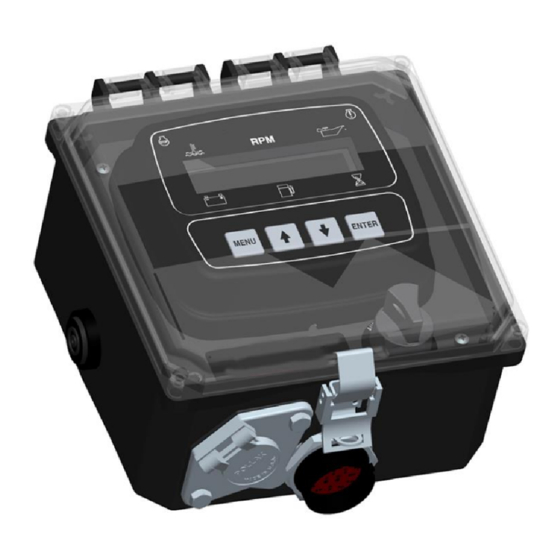
Engine Display & Control
Mechanical Engine
Part Number: C3M-2514-AS
Revision: 3.2
______________________________________________________________________________________________________________________________________
Copyright Controls, Inc.
P.O. Box 368 • Sharon Center, OH 44274
Phone 330.239.4345 • Fax 330.239.2845 • www.controlsinc.com
Advertisement
Table of Contents

Related Manuals for Controls C3M-2514-AS


Summary of Contents for Controls C3M-2514-AS
- Page 1 Product Manual Engine Display & Control Mechanical Engine Part Number: C3M-2514-AS Revision: 3.2 ______________________________________________________________________________________________________________________________________ Copyright Controls, Inc. P.O. Box 368 • Sharon Center, OH 44274 Phone 330.239.4345 • Fax 330.239.2845 • www.controlsinc.com...
-
Page 2: Table Of Contents
TABLE OF CONTENTS PANEL OPERATION …………….…………………………………………………………………………………….…………………………….………. MANUAL OPERATION AUTO START OPERATION MODULE CONNECTORS …………………………………………………………………………………………………….………………….………. PRIMARY 14 PIN MODULE CONNECTOR PANEL CONNECTOR ……...………………………………………………...……………………………………………………………………..………. 16 PIN ENGINE HARNESS CONNECTOR ENGINE ALARMS, CODES AND MESSAGES ……………………………………………………………………………..………... WARNINGS & ALARMS ALARM EVENT LOG INDICATION LAMPS CONTROL PANEL SPECIFIC ALARMS AND SHUT DOWNS ………………………………………….…………..………... -
Page 3: Panel Operation
PANEL OPERATION MANUAL OPERATION 1) Engine Start - Turn key to CRANK position 2) Engine Stop - Turn key to OFF position AUTO START/STOP OPERATION 1) Engine Start - Turn key to AUTO position Engine start/stop based on auto start/stop settings. Panel display shows “Auto Start ARMED” message. -
Page 4: Module Connectors
MODULE CONNECTORS Primary Connector 14 Pin MODULE CONNECTOR (14 Pin) Function Function Fuel Solenoid/10 amp Water Temp Battery Positive Battery Positive Key Auto Detect Auto Crank Signal/ 10 amp Switched Power to C3M Preheat Signal 5 amp Battery Negative RY #1 Start Warning/5 amp Fuel Level Oil Pressure Remote Start Input... -
Page 5: Panel Connector
PANEL CONNECTORS 1. Engine Harness Connector –Deutsch 16 pin (HDP24-24-21PE) 16 Pin Engine Harness Connector Function Battery Positive Battery Negative Key On Power (Fuel/Run Signal) Preheat Signal Crank Signal Oil Pressure Sender Input Engine Temperature Sender Input MPU- MPU+ or Tach Input Alternator Excite Fuel Level or Aux Switch Input Fuel Pull in output... -
Page 6: Engine Alarms, Codes And Messages
ENGINE ALARMS, CODES AND MESSAGES WARNINGS & ALARMS When parameter is outside of its limits, the control panel flashes that parameter the display and illuminates the yellow lamp. If the condition worsens beyond the alarm set point, the red lamp illuminates, the engine shuts down and an alarm message appears on the display identifying the cause. -
Page 7: Indication Lamps
INDICATION LAMPS The panel has two lamp indicators. Engine Engine Warning Fault/Shutdown Lamp Lamp... -
Page 8: Control Panel Specific Alarms And Shut Downs
CONTROL PANEL SPECIFIC ALARMS AND SHUT DOWNS The panel has its own engine safety alarms and shut downs that can be enabled. These alarms and shut downs are managed by the control panel. The available options are listed below and can be accessed via the Engine Safety Configuration menu. -
Page 9: Control Panel Digital Input
CONTROL PANEL DIGITAL INPUT The panel provides the analog and digital inputs defined below located in the Input Configuration menu. The panel is shipped from the factory with the highlighted inputs enabled in the panel. Inputs not highlighted need to be enabled/configured in the menu system to be used. Input Heading Default... -
Page 10: Control Panel Relay Outputs
CONTROL PANEL RELAY OUTPUTS The panel provides relay outputs defined below located in the Output Configuration menu. The relays are rated at 5 amps. The panel is shipped from the factory with the highlighted outputs enabled and pre- wired in the panel. Relay Heading Default... - Page 11 g. Alarm Horn - Energizes an external audible alarm when an alarm condition is present. Pressing the ENTER button will silence. h. Engine Run - Relay will be active when engine RPM is greater than 600. Typically used to drive an auxiliary circuit such as louvers or send a signal to a monitoring station. Switch Trip - Relay will be active if digital input is active.
-
Page 12: Menu System
MENU SYSTEM To Enter Menu System Hold MENU button and press ENTER button. Menu Navigation Press MENU button to scroll menu options. Press the UP arrow button to enter menu. Press the DOWN arrow button to reverse. Exit Menu System Hold MENU button and press ENTER button. -
Page 13: Configuration Menus
CONFIGURATION MENUS Input Configuration Digital Input 1 – Pre Set to Auto Start Output Configuration Relay Output 1 – Pre Set to Start Alarm Relay Output 2 - Pre Set to Fuel/Run Relay Output 3 - Pre Set to Preheat Relay Output 4 - Pre Set to Crank Signal Throttle Configuration Throttle Type - Throttle Type Selection (Default = Off) - Page 14 Module Configuration Hour Meter Clear Operation Log Yes/No Clear Alarm Log Yes/No LCD Auto Contrast On/Off LCD Contrast (Default = 55%) LCD Backlight (Default = 100%) VFD Intensity (Default = 100%) Auto Start Configuration Auto Start Delay (Default = 10 seconds) Pre Heat Time (Default = 4 seconds) Crank Time (Default = 10 seconds) Crank Rest Time ( Default = 10 seconds)
Need help?
Do you have a question about the C3M-2514-AS and is the answer not in the manual?
Questions and answers