Table of Contents
Advertisement
Quick Links
Product Manual
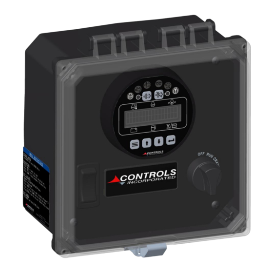
Part Number: MVP-A7302
Revision: 1.1
______________________________________________________________________________________________________________________________________
Copyright Controls, Inc.
P.O. Box 368 • Sharon Center, OH 44274
Phone 330.239.4345 • Fax 330.239.2845 • www.controlsinc.com
Advertisement
Table of Contents

Related Manuals for Controls MVP-A7302


Summary of Contents for Controls MVP-A7302
- Page 1 Product Manual Part Number: MVP-A7302 Revision: 1.1 ______________________________________________________________________________________________________________________________________ Copyright Controls, Inc. P.O. Box 368 • Sharon Center, OH 44274 Phone 330.239.4345 • Fax 330.239.2845 • www.controlsinc.com...
-
Page 2: Table Of Contents
CONTROLS, INCORPORATED C O N T R O L S Y S T E M S & S O L U T I O N S TABLE OF CONTENTS PRIOR TO ENGINE START ………………...…………………………………………………………………….….…….……….…………... CAN Bus CONFIGURATION THROTTLE SETTINGS …………………………..………………………………….……………………………………….….……………….. -
Page 3: Prior To Engine Start
CONTROLS, INCORPORATED C O N T R O L S Y S T E M S & S O L U T I O N S Prior to starting the engine, select the proper throttle control mode and parameters required for application. -
Page 4: Throttle Settings
CONTROLS, INCORPORATED C O N T R O L S Y S T E M S & S O L U T I O N S Throttle Settings The following bolded settings are required for manual (and automatic) operation in the Throttle Configuration menu. -
Page 5: Installation Information
CONTROLS, INCORPORATED C O N T R O L S Y S T E M S & S O L U T I O N S INSTALLATION INFORMATION - 4 -... -
Page 6: Connector Information
CONTROLS, INCORPORATED C O N T R O L S Y S T E M S & S O L U T I O N S CONNECTOR INFORMATION - 5 -... - Page 7 CONTROLS, INCORPORATED C O N T R O L S Y S T E M S & S O L U T I O N S ENGINE HARNESS CONNECTOR INFORMATION Engine Harness Connector –Deutsch 21 pin (HDP24-24-21PE) 21 Pin Connector...
-
Page 8: Engine Alarms, Codes And Messages
CONTROLS, INCORPORATED C O N T R O L S Y S T E M S & S O L U T I O N S ENGINE ALARMS, CODES AND MESSAGES Engine ECU Alarm/De-Rate/Shut Downs It is important to understand panel operation with respect to engine safety protections, alarms, and fault codes. -
Page 9: Active And Stored Engine Ecu Codes
CONTROLS, INCORPORATED C O N T R O L S Y S T E M S & S O L U T I O N S Indicator Lamps Regen Regen Lamp Inhibit Active Engine Engine Lamp Lamp Fault Lamp Alarm... -
Page 10: Control Panel Analog And Digital Inputs
CONTROLS, INCORPORATED C O N T R O L S Y S T E M S & S O L U T I O N S CONTROL PANEL ANALOG AND DIGITAL INPUTS The panel has one analog input and up to one digital input available to monitor other components, senders or signals. - Page 11 CONTROLS, INCORPORATED C O N T R O L S Y S T E M S & S O L U T I O N S Analog 1 Function Options 1) Fuel Level S-W – Fuel amount, in percentage, can be measured and displayed using a standard Stewart Warner scale sender of 240 ohms –...
-
Page 12: Menu System
CONTROLS, INCORPORATED C O N T R O L S Y S T E M S & S O L U T I O N S MENU SYSTEM To Enter Menu System Hold MENU button and press ENTER button. Menu Navigation Press MENU button to scroll menu options. - Page 13 CONTROLS, INCORPORATED C O N T R O L S Y S T E M S & S O L U T I O N S Main Menus Main Menus Sub Menus Emissions Parameters View/Scroll Active Fault Codes Active Engine Fault Codes...
- Page 14 CONTROLS, INCORPORATED C O N T R O L S Y S T E M S & S O L U T I O N S Configuration Menus Input Configuration Analog 1 Function Digital Input Function Digital B1 Function Digital B2 Function...
-
Page 15: Emissions Monitoring
CONTROLS, INCORPORATED C O N T R O L S Y S T E M S & S O L U T I O N S EMISSIONS MONITORING Emissions Information The panel provides lamp indications, display messages and other emission related information. - Page 16 CONTROLS, INCORPORATED C O N T R O L S Y S T E M S & S O L U T I O N S Regeneration The regeneration process is controlled by the engine ECU. The engine ECU monitors emissions parameters such as soot level and ash level.
- Page 17 CONTROLS, INCORPORATED C O N T R O L S Y S T E M S & S O L U T I O N S DPF Lamp DPF Lamp (Blinking) (Blinking) At the most severe level, the DPF lamp blinks and the red engine alarm lamp illuminates.
- Page 18 CONTROLS, INCORPORATED C O N T R O L S Y S T E M S & S O L U T I O N S Regen Lamp Active Lamp The regeneration active lamp illuminates during the regeneration process. The DFP lamp stays illuminated until the engine ECU determines that a regeneration is no longer required.
Need help?
Do you have a question about the MVP-A7302 and is the answer not in the manual?
Questions and answers