Advertisement
Quick Links
HAZARDOUS ROOM SERIES
Installation & Operation Instructions
PRECAUTIONS
• DO NOT RUN THE WIRING IN ANY CONDUIT
WITH LINE VOLTAGE (24/120/230 VAC).
GENERAL INFORMATION
The ACI Hazardous Room Sensor is a single point
wall mounted temperature sensor that is designed
for use with electronic controllers in commercial and
industrial heating and cooling building manage-
ment systems. It is available with multiple thermistor
or RTD options. Hazardous Room sensors come
standard with a heavy-duty Copper-Free Aluminum
Connection Head that meets Class I, Division 1 & 2,
Group A, B, C, D; Class II, Division 1, Groups E, F, G;
Class II, Division 2, Group F & G; class III standards.
For optimal temperature measurement, follow
these tips:
• Do not install on external walls.
• Do not install near heat sources. eg: lamps, radiators,
direct sunlight, copiers, chimney walls, walls concealing
hot-water pipes.
• Avoid air registers, di users, vents, and windows
MOUNTING INSTRUCTIONS
This product must be installed by a trained profession-
al with knowledge of local codes and regulations. Before carrying out any work, ensure local regulations and
site procedures are followed to maintain the overall certi cation of the sensor. The sensor should be mounted
in an area where air circulation is well mixed and not blocked by obstructions.
For mounting on a wall, ACI recommends a height of 48-60" (1.2-1.5 m) o the ground and at least 1.5' (0.5
m) from the adjacent wall. Remove the cover from the housing by twisting o the cover. Attach the base
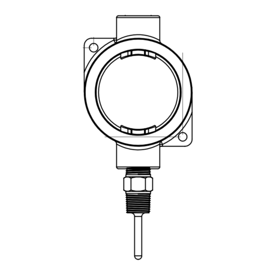
directly to the wall. Mounting holes are located at the corners of the housing – see FIGURE 1 (above). Seal
ttings, intrinsically safe barriers, and explosion proof ex ttings not provided by ACI.
Drill pilot holes for the mounting screws. Use the enclosure mounting holes as a guide, or use the
dimensions listed in FIGURE 1(p. 1). A 1/2" NPT tapping is located at the top of the enclosure.
Refer to the wiring instructions (p 2) to make necessary connections. The housing is provided with Green ground
screw if the housing requires an earth ground. After wiring, attach the cover to the base.
Automation Components, Inc.
2305 Pleasant View Road | Middleton, WI 53562
Phone: 1-888-967-5224 | Website: workaci.com
FIGURE 1: ENCLOSURE
(78.59 mm)
Page 1
Phone: 1-888-967-5224
Website: workaci.com
3.09"
SEAL FITTING
Version: 1.0
I0000816
Advertisement

Related Manuals for aci HAZARDOUS ROOM Series


Summary of Contents for aci HAZARDOUS ROOM Series
- Page 1 For mounting on a wall, ACI recommends a height of 48-60” (1.2-1.5 m) o the ground and at least 1.5’ (0.5 m) from the adjacent wall. Remove the cover from the housing by twisting o the cover. Attach the base directly to the wall.
- Page 2 FIGURE 3: 2-WIRE THERMISTOR or RTD WIRING INSTRUCTIONS WIRING All thermistor type units are supplied with (2) ying lead wires, and all RTD’s are supplied with (2) or (3) ying lead wires – see FIGURE 3 and 4. The number of wires WIRING FROM CONTROLLER WIRE NUT THERMISTOR OR...
- Page 3 Do not dispose of with household waste. Do not burn. WARRANTY The ACI Hazardous Series temperature sensors are covered by ACI’s Five (5) Year Limited Warranty, which is located in the front of ACI’S SENSORS & TRANSMITTERS CATALOG or can be found on ACI’s website: www.workaci.com.
Need help?
Do you have a question about the HAZARDOUS ROOM Series and is the answer not in the manual?
Questions and answers