aci ROOM Series Installation & Operation Instructions
Hide thumbs
Also See for ROOM Series:
- User manual (17 pages) ,
- Installation & operation instructions (8 pages) ,
- Installation & operation instructions (4 pages)
Table of Contents
Advertisement
Quick Links
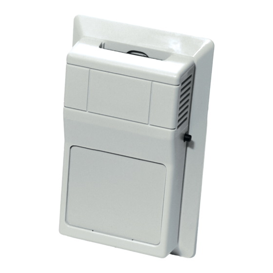
ROOM SERIES
Installation & Operation Instructions
PCB: HO
PRECAUTIONS
• DO NOT RUN THE WIRING IN ANY CONDUIT
WITH LINE VOLTAGE (24/120/230 VAC).
GENERAL INFORMATION
The HO/20K-RSO series is a system speci c sensor
that is polarity sensitive but not position sensitive.
This
unit
is
available
con gurations including Room w/ Override, and
Room w/ Setpoint, and Room w/ Override, and
Setpoint. RS232 Communication jack options are
available upon request.
MOUNTING INSTRUCTIONS
Take care when mounting. Check local code for
mounting height requirements. Typical mounting
heights are 48-60" (1.2-1.5 m) o the ground and at
least 1.5' (0.5 m) from the adjacent wall. The sensor
should be mounted in an area where air circulation is
well mixed and not blocked by obstructions.
Separate the cover from the base. Attach the base
directly to the wall or to a standard 2" x 4" junction
box using the (2) #6-32 x 1" screws provided.
*Reference FIGURE 2 (next page)
For optimal temperature measurement, follow
these tips:
• Do not install on external walls.
• Avoid air registers, di users, vents, and windows.
• Avoid con ned areas such as shelves, closed
cabinets, closets, and behind curtains.
• Eliminate and seal all wall and conduit penetrations.
Air migration from wall cavities may alter
temperature readings.
• A thermally-insulated backing should be used when
tting to solid walls (concrete, steel, etc.). ACI part:
A/ROOM-FOAM-PAD
• Do not install near heat sources, eg: lamps,
radiators, direct sunlight, copiers, chimney
walls, walls concealing hot-water pipes.
Refer to the Wiring Instructions (p. 2-3) to make
necessary connections. Tighten the cover down,
using the (2) 1/16" Allen screws located in the
bottom of the housing. A 1/16" Hex driver is
needed to secure the cover to the base.
Automation Components, Inc.
2305 Pleasant View Road | Middleton, WI 53562
Phone: 1-888-967-5224 | Website: workaci.com
in
many
di erent
Page 1
FIGURE 1: ROOM DIMENSIONS
ROOM, VERSION 1
[R]
2.75"
(69.85 mm)
FRONT
BOTTOM
ROOM, VERSION 2
[R2]
2.75"
(69.85 mm)
FRONT
BOTTOM
Phone: 1-888-967-5224
Website: workaci.com
1.12"
(28.55 mm)
4.50"
(114.30 mm)
RIGHT
1.12"
(28.55 mm)
4.50"
(114.30 mm)
RIGHT
Version: 4.0
I0000112
Advertisement
Table of Contents

Subscribe to Our Youtube Channel
Related Manuals for aci ROOM Series


Summary of Contents for aci ROOM Series
- Page 1 FRONT RIGHT • A thermally-insulated backing should be used when tting to solid walls (concrete, steel, etc.). ACI part: A/ROOM-FOAM-PAD • Do not install near heat sources, eg: lamps, radiators, direct sunlight, copiers, chimney walls, walls concealing hot-water pipes.
- Page 2 FIGURE 2: MOUNTING WIRING INSTRUCTIONS ACI recommends 16 to 26 AWG twisted pair wires or OPTIONAL INSULATING GASKET shielded cable for all sensors. Signal wiring must be run separate from low and high voltage wires (24/120/230 VAC). All ACI thermistors are both non-polarity and non-position sensitive.
- Page 3 C-BUS DEVICES prevent any chance of shorting. ISOLATED Note: ACI’s stats are not two-way communicating. Communication jacks allow the user to query and modify operating parameters of the local room terminal unit from the portable operator’s terminal (laptop). This feature allows a technician to commission or service the controller via the sensor.
- Page 4 Accuracy @ 0-70 °C (32 - 158 °F): WARRANTY The ACI Room Series temperature sensors are covered by ACI’s Five (5) Year Limited Warranty, which is located in the front of ACI’S SENSORS & TRANSMITTERS CATALOG or can be found on ACI’s website: www.workaci.com.
Need help?
Do you have a question about the ROOM Series and is the answer not in the manual?
Questions and answers