Advertisement
Quick Links
!
WARNING:
This product is not intended to be used for Life or Safety applications.
•
This product is not intended for use in any hazardous or classified locations.
•
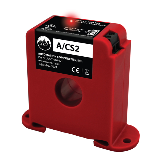
The A/CS2 and A/SCS2 Series Current Switches must be used on Insulated Conductors Only!
•
HIGH VOLTAGE:
Disconnect and lock out all power sources before installation as severe injury or death may result from electrical
•
shock due to contact with high voltage wires.
Never rely on the Red LED to determine whether power is present at the current switch. At very low monitored
•
input currents the Red LED may not light to indicate the current is above the trip point.
Installation
Make sure that all installations are in compliance with all national and local electrical codes. Only qualified individuals that are
familiar with codes, standards, and proper safety procedures for high-voltage installations should attempt installation. The current
switches will not require external power, since the power for the current switch is induced from the conductor being monitored.
The current switch may be mounted in any position using the two #8 x 3/4" Tek screws and the mounting holes in the base, or
snapped directly on to the 35mm DIN rail (See Figure 1). Leave a minimum distance of 1" (3 cm) between the current switch and
any other magnetic devices such as contactors and transformers.
Latch Operation for A/SCS2 Series
Press down on the side tab and swing the top of the unit up to open the split core current switch as shown in Figure 2. Press down
firmly on the cover to close the current switch. An audible "click" will be heard as the tab slides over the tongue on the base.
!
CAUTION: Mating surfaces of the magnetic core are exposed when the sensor is open. Electrical contact grease, present on
the cores to prevent corrosion, can capture grit and dirt if care is not exercised. Operation can be impaired if anything prevents
good contact between pole pieces. Visually check the mating parts of the core before closing the current sensor.
AUTOMATION COMPONENTS, INC
Please Read Instructions Carefully Before Installation!
Figure 1: Sensor Placed on Rail
Figure 2: Opening A/SCS2 Series
Installation and Operation Instructions
A/SCS2, A/SCS2-L, A/SCSX2
Page 1 of 3
Part # A/CS2, A/CSX2
Version : 3.0
I0000787
Advertisement

Related Manuals for aci A/CS2


Summary of Contents for aci A/CS2
- Page 1 • This product is not intended for use in any hazardous or classified locations. • The A/CS2 and A/SCS2 Series Current Switches must be used on Insulated Conductors Only! • HIGH VOLTAGE: Disconnect and lock out all power sources before installation as severe injury or death may result from electrical •...
- Page 2 Operating Current of the Monitored Device, add one (1), then round up to the nearest whole number. Example: When using the A/CS2, a small fan operating at 0.1A should be wrapped through the sensor four times to give you a total operating current of 0.4 Amps flowing through the A/CS2.
- Page 3 Remove all debris or dust manually and close the current sensor, See Figure 2. Retest the sensor in your application. specifications. ACI Model # Fixed Trip Point Resistance if switch open Resistance if switch closed A/CS2 0.25 Amps...
Need help?
Do you have a question about the A/CS2 and is the answer not in the manual?
Questions and answers