Table of Contents
Advertisement
Quick Links
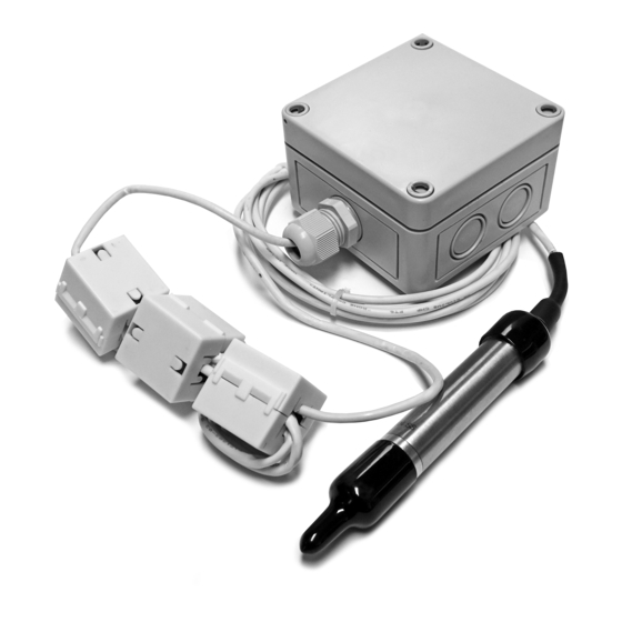
REMOTE PROBE HUMIDITY/
TEMPERATURE TRANSMITTER
SERIES
Installation & Operation Instructions
GENERAL INFORMATION
The A/TT Remote Probe Series sensors and
transmitters are single point sensors that
output 4-20 mA with an optional voltage
signal output of 1-5VDC or 2-10VDC signal.
The sensor is designed for use with electronic
controllers in commercial heating and
cooling building management systems. All
A/TT temperature transmitters can be
powered from either an unregulated or
regulated 8.5-32 VDC power supply.
The A/RH Remote Probe Series sensor is a
relative humidity transmitter that can be
powered with either an AC or DC supply
voltage. The RH Remote Probe transmitter is
eld selectable with a 4-20 mA, 0-5 VDC, or
0-10 VDC output signal that is equivalent to 0
to 100% RH. All RH units are shipped from the
factory set to 4-20 mA output.
For optimal readings, follow these tips:
• Do not install on external walls.
• Avoid air registers, di users, vents, and windows.
• Eliminate and seal all wall and conduit penetrations. Air migration from wall cavities may alter temperature readings.
• Do not install near heat sources. eg: lamps, radiators, direct sunlight, copiers, chimney walls, walls concealing
hot-water pipes.
MOUNTING INSTRUCTIONS
Remote Probe sensors may be mounted using a 3/4" mounting clip on walls or with cable ties. The sensor
should be mounted in an area where air circulation is well mixed and not blocked by obstructions.
The RH Remote Probe includes a Black Rubber Cap that ts over the sensor lter. This cap should be placed
on the sensor lter during wet/wash down processes. The cap must be removed for normal operation.
TRANSMITTER MOUNTING
Attach the base directly to the wall by rst drilling pilot holes for the mounting screws. Alternatively, you
may refer to the dimensions listed in FIGURE 1 (top) to measure out.
SENSOR MOUNTING
To x the probe on a wall, ACI recommends a height of 48-60" (1.2-1.5 m) o the ground and at least 1.5' (0.5
m) from the adjacent wall. Slide the sensor probe through the mounting clip - see FIGURE 2 (p. 2). Drill a
screw through the socket and tighten to the wall. Refer to Wiring Instructions (p. 2-4) to make necessary
connections.
Automation Components, Inc.
2305 Pleasant View Road | Middleton, WI 53562
Phone: 1-888-967-5224 | Website: workaci.com
FIGURE 1: ENCLOSURE
DIMENSIONS
NEMA 4X (-4X)
3.70"
(93.98 mm)
3.70"
(93.98mm)
2.21"
(56.07mm)
Page 1
Phone: 1-888-967-5224
Website: workaci.com
3.11"
(78.99 mm)
0.90"
(22.78mm)
0.75"
(19.05mm)
Version: 6.0
I0000829
3.56"
(90.42mm)
0.91"
(23.11mm)
Advertisement
Table of Contents

Related Manuals for aci A/TT Remote Probe Series


Summary of Contents for aci A/TT Remote Probe Series
- Page 1 SENSOR MOUNTING To x the probe on a wall, ACI recommends a height of 48-60” (1.2-1.5 m) o the ground and at least 1.5’ (0.5 m) from the adjacent wall. Slide the sensor probe through the mounting clip - see FIGURE 2 (p. 2). Drill a screw through the socket and tighten to the wall.
- Page 2 Open the cover of the enclosure. The temperature transmitter is located on the bottom of the enclosure. TEMPERATURE TRANSMITTER BOARD ACI recommends 16 to 26 AWG twisted pair wires or shielded cable for all transmitters. FIGURE 4: SHARED POWER CONNECTIONS and ANALOG OUTPUTS...
- Page 3 FIGURE 5 (top) for wiring diagrams. All wiring must ZERO SPAN comply with local and National Electric Codes. All ACI TT and TTM temperature transmitters can be powered from either an unregulated or regulated 8.5 to 32VDC power supply. The TT and TTM DO NOT support an AC...
- Page 4 DC SUPPLY VOLTAGE transmitter is located on the inside of the cover. 4-20 mA OUTPUT ACI recommends 16 to 26 AWG twisted pair wires or shielded cable for all transmitters. Twisted pair may be used for 2-wire current output transmitters or 3-wire for voltage output. Refer to...
- Page 5 7.50 / 0.10 = 75% RH WARRANTY The ACI Remote Probe Series RH sensors are covered by ACI’s Five (5) Year Limited Warranty, which is located in the front of ACI’S SENSORS & TRANSMITTERS CATALOG or can be found on ACI’s website: www.workaci.com.
-
Page 6: Product Specifications
PRODUCT SPECIFICATIONS CABLE & ENCLOSURE Minimum Cable Bend Radius: 1.92” (48.77 mm) or 10x the Cable Diameter Cable Ratings | Cable Jacket Material: UL (CMP, CL3P, FPLP); CSA(CMP, FT6), Plenum Rated | Polyvinyl Chloride (PVC) Cable Operating Temperature Range: 32 to 167 °F (0 to 75 °C) Enclosure Speci cations: (Material, “-4X”... -
Page 7: Troubleshooting
If the sensor is brand new, leave the sensor powered for at least 30 minutes to stabilize. • If you suspect that the transmitter is not reading within the speci ed tolerance, please contact ACI for further assistance. TEMPERATURE PROBLEM No Reading •... - Page 8 Automation Components, Inc. 2305 Pleasant View Road Middleton, WI 53562 Phone: 1-888-967-5224 Website: workaci.com Page 8 Automation Components, Inc. Version: 6.0 2305 Pleasant View Road | Middleton, WI 53562 I0000829 Phone: 1-888-967-5224 | Website: workaci.com...
Need help?
Do you have a question about the A/TT Remote Probe Series and is the answer not in the manual?
Questions and answers