Table of Contents
Advertisement
Quick Links
TUC2 / TUCH2
Installation & Operation Instructions
GENERAL INFORMATION
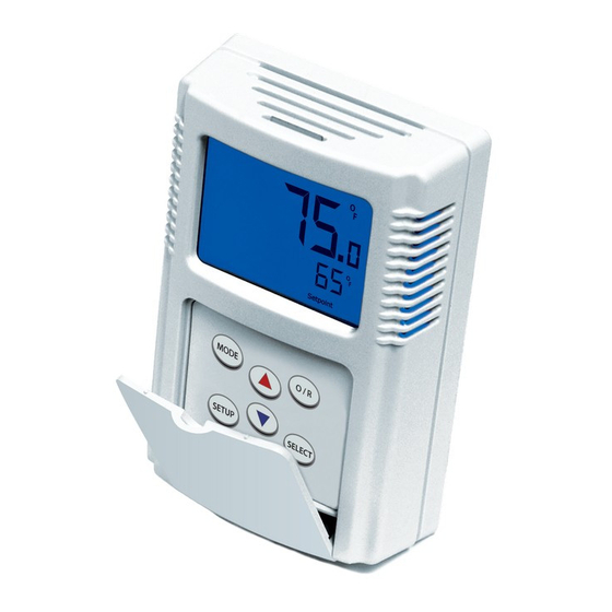
The TUC2 provides temperature space monitoring with a
backlit LCD. The TUCH2 provides temperature and relative
humidity monitoring with a backlit LCD. Depending on the
con guration, the units can display and output Temperature,
Relative Humidity, Setpoint, Fan Speed, System Status, and
Occupied/Unoccupied Status.
The TUC2 and TUCH2 supports single temperature sensor
Operation for several common sensor types and it provides the
exibility to choose from numerous setpoint output options.
The TUCH2 supports relative humidity output in all standard
analog signals at 2%, 3%, or 5% accuracy. A setup menu
provides easy output and display con guration changes.
MOUNTING INSTRUCTIONS
Carefully separate the cover from the base by pulling the
cover and base apart towards the bottom of the device. The
hex screws(1/16" Allen) may need to be turned in to release
the cover. Route the wires through the access hole in the
center of the base and screw them into the terminal blocks.
Refer to the wiring instructions to make the necessary
connections. Attach the base directly to drywall, or to a
standard 2" x 4" junction box using the hardware provided.
*Reference FIGURE 2 (p. 2)
PRECAUTIONS
• Do not run the temperature sensor wiring in any
conduit with line voltage (24/120/230 VAC) if utilizing
resistance temperature signal.
• Remove power before wiring. Never connect or
disconnect wiring with power applied.
• When using a shielded cable, ground the shield only at
the controller end. Grounding both ends can cause a
ground loop.
• It is recommended you use an isolated UL-listed class 2
transformer when powering the unit with 24 VAC.
Automation Components, Inc.
2305 Pleasant View Road | Middleton, WI 53562
Phone: 1-888-967-5224 | Website: workaci.com
FIGURE 1: ENCLOSURE DIMENSIONS
4.56"
(115.88 mm)
FRONT
BOTTOM
SIDE
Page 1
Phone: 1-888-967-5224
Website: workaci.com
3.00"
(76.19 mm)
1.33"
(33.77 mm)
Version: 6.0
I0000621
Advertisement
Table of Contents

Related Manuals for aci TUC2


Summary of Contents for aci TUC2
- Page 1 Website: workaci.com GENERAL INFORMATION FIGURE 1: ENCLOSURE DIMENSIONS The TUC2 provides temperature space monitoring with a backlit LCD. The TUCH2 provides temperature and relative humidity monitoring with a backlit LCD. Depending on the con guration, the units can display and output Temperature, Relative Humidity, Setpoint, Fan Speed, System Status, and Occupied/Unoccupied Status.
- Page 2 16 to 26 AWG twisted pair wires or shielded cable for all sensors. Be sure to connect the cable shield to the ground at the controller only. The number of wires needed depends on the application, with 3 wires minimum required to support the outputs of the TUC2 unit.
- Page 3 WIRING INSTRUCTIONS (Continued) TERMINAL CONNECTIONS Note: If your TUC2 or TUCH2 has any output BLOCKS con gured with a 10V or Current output, the +12 to +40 VDC or 20 to 28 VAC voltage at the +V terminal must be at least +18 Ground or signal common, 20 to 28 VAC VDC.
- Page 4 OPERATION FIGURE 6: KEYPAD Keypad The keypad comes in a 2 button, 3 button, 4 button, 5 button, MODE or 6 button version. A 6 button keypad is needed for fan or system mode. A 3 button or 5 button keypad is needed for SETUP SELECT override mode.
- Page 5 OPERATION (Continued) Setup Mode (Continued) Press to return to the previous menu. If no keys are pressed for 15 seconds the unit will automatically return to normal SETUP operation. Setup Menu The full setup menu with descriptions of all the options is shown on page 6. The setup menu will change depending on the con guration ordered.
- Page 6 FULL SETUP MENU Page 6 Automation Components, Inc. Version: 6.0 2305 Pleasant View Road | Middleton, WI 53562 I0000621 Phone: 1-888-967-5224 | Website: workaci.com...
- Page 7 1/16” Allen screws (2 qty) / 1/16” Hex Driver WARRANTY The A/TUC2 Series and the A/TUCH2 Series are covered by ACI’s Five (5) Year Limited Warranty, which is located in the front of ACI’S SENSORS & TRANSMITTERS CATALOG or can be found on ACI’s website: www.workaci.com.
Need help?
Do you have a question about the TUC2 and is the answer not in the manual?
Questions and answers