Advertisement
ACI
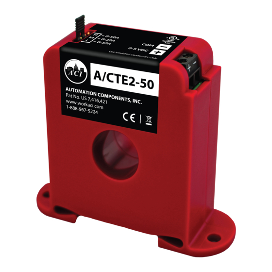
Automation Components, Inc.
Safety
This product is not intended to be used for Life or Safety applications.
!
This product is not intended for use in any hazardous or classified locations.
Disconnect and lock out all power sources before installation as severe injury or death may result from electrical
shock due to contact with high voltage wires.
Installation
Disconnect and lock out all power sources before installation as severe injury or death may result from electrical shock due to
contact with high voltage wires. Make sure that all installations are in compliance with all national and local electrical codes.
Only qualified individuals that are familiar with codes, standards, and proper safety procedures for high-voltage installations
should attempt installation. The current sensor will not require external power, since the power for the current sensor is
induced from the conductor being monitored.
The A/CTE & A/CTV Series Analog Current Sensors should be used on Insulated Conductors Only! The current sensors may be
mounted in any position using the (2) #8 x 3/4" Tek screws and the mounting holes in the base or snapped directly on to the 35mm
DIN rail (See Figures 1 & 2 below). Leave a minimum distance of 1" (3 cm) between the current sensor and any other magnetic
devices such as contactors and transformers.
3X
Figure 1: Sensor Placed on Rail
Wiring
ACI recommends the use of a 2 conductor 16 to 22 AWG shielded cable,or copper wire only for all Analog current sensor
installations. A maximum wire length of less than 30 meters (98.4 feet) should be used between the A/CTE and A/CTV series
current sensors and the Building Management System or controller. Note: When using a shielded cable, be sure to connect only
(1) end of the shield to ground at the controller. Connecting both ends of the shield to ground may cause a ground loop. When
removing the shield from the sensor end, make sure to properly trim the shield so as to prevent any chance of shorting. The current
sensors terminals are polarity sensitive and represent a linear 0 to 5 or 0 to 10 VDC output signal. The recommended torque to be
used on the terminal block connections is 0.67 Nm or 5.93 in-lbs. The aperture (hole) size of the current sensor is 0.75" (1.90 cm)
and will accept a maximum cable diameter of 350 MCM's.
Please Read Instructions Carefully Before Installation!
2305 Pleasant View Rd. Middleton Industrial Park Middleton, WI 53562
PH: (608) 831-2585 FAX (608) 831-7407
File Name: I0000141 Rev 6.Doc
Installation and Operation Instructions
3X
Figure 2: Sensor Removed From Rail
Page 1 of 3
Part # A/CTE-50, A/CTE-250,
A/CTV-50, A/CTV-250
Advertisement
Table of Contents

Related Manuals for aci A/CTE-50


Summary of Contents for aci A/CTE-50
- Page 1 Wiring ACI recommends the use of a 2 conductor 16 to 22 AWG shielded cable,or copper wire only for all Analog current sensor installations. A maximum wire length of less than 30 meters (98.4 feet) should be used between the A/CTE and A/CTV series current sensors and the Building Management System or controller.
- Page 2 Operating Specifications ACI Model # Output Range Jumper * Max. Sensing Max. Continuous Max. Current for Current Voltage Current 6 seconds 0-10 Amps 600 VAC 100 Amps 125 Amps A/CTE-50 0 to 5 VDC 0-20 Amps Middle 150 Amps...
- Page 3 WEEE Directive At the end of their useful life the packaging and product should be disposed of via a suitable recycling centre. Do not dispose of with household waste. Do not burn. LISTED IND.CO NT.EQ . 3JHX 2305 Pleasant View Rd. Middleton Industrial Park Middleton, WI 53562 PH: (608) 831-2585 ...
Need help?
Do you have a question about the A/CTE-50 and is the answer not in the manual?
Questions and answers